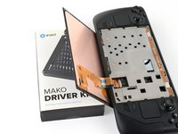
crwdns2915892:0crwdne2915892:0
Use this guide to remove or replace the front shell (or front cover) on your Steam Deck OLED.
This procedure involves almost a complete disassembly, including removal of the screen! Know what you're getting yourself into.
Remember to follow general electrostatic discharge (ESD) safety procedures while repairing your device.
You'll need replacement thermal paste, screen adhesive, speaker adhesives, and ambient light sensor adhesives to complete this repair.
Some photos in this guide may contain slight visual discrepancies, but won't affect the procedure.
crwdns2942213:0crwdne2942213:0
-
-
Power down your Steam Deck and unplug any cables.
-
-
-
Measure 3 mm from the tip and mark the opening pick with a permanent marker.
Got to step 2 and realized the fix kit doesn't include an opening pick! Looks like a guitar pick, and I have those lying around. Is that expected? Looks like the pick is used in many steps below. There's a little blue crowbar that isn't mentioned in the instructions. Perhaps that replaces the opening pick?
Hi! I can't see which guide you were using when writing this comment. Can you reply here with which guide and fix kit you used?
I see you posted this in Meta. I hope it's resolved soon! In the meantime, a guitar pick may work well enough for your repair.
what fix kit?
My fix kit didn't include an opening pick either
Make sure you check inside the black boxes after emptying them. My pick was stuck inside one of the boxes.
My AliExpress refurbished screen came with a pick that has a coin-like circle that pops out, so no modification was necessary
the picture shows 3 cm but the description says 3 mm's. Which one is it?
That is a misunderstanding. It is a ruler with a scale for cm, it shows 0.3 cm, i.e. 3 mm.
VauWeh -
Oh, come ON!
Big Ed -
It will ALWAYS be millimeters on a phone, but this step is ridiculous, skip it!
@leifdewolf I wouldn't skip it for a first repair.
It's not an Ifixit KIT if it doesn't include everything. You'll need to order the opening pic separately. Or head to Walmart like myself and look for guitar pics. Hopefully, this will work just as well.
No pick in mine as well. It’s really not clear that you have to order this separately when ordering an IPhone SE 202/2022 screen repair kit. Is this the case?
Frustrated, I ordered a compact package where everything was encapsulated. Useless suction tools could not separate the screen. If it is unable to decouple the screen, then why sucking suction tools you have provided.
For my kit the triangle pick was stuck inside the box with the screen not with the other tools maybe it's also there for you
Y’all are getting far, FAR too detailed with some of this stuff…. Measuring and marking the pick that you won’t actually use to open the device?!? lol that’s kinda funny. Just heat it up, grab a spudger, and the back just pops right off! The iFixit tech need to stick to the KISS method more often, you know KEEP IT SIMPLE STUPID!!! Like l, for reals, I’ve been doing this stuff for YEARS and using iFixit guides regularly and this is just ridiculous at this point!
Will the phone still work if the sensor assembly on the back of the screen is damaged?
I don't have a pick, but how much better are these picks than an old credit card for opening an iPhone 13 mini?
The pick in my iFixIt kit was packed with the battery, not with the rest of the toolkit.
-
-
-
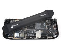
Prepare an iOpener and apply it to the top edge of the screen for one minute.
-
-
-
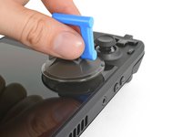
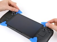
Apply a suction handle to the top left corner of the screen, as close to the top edge as possible.
-
-
-
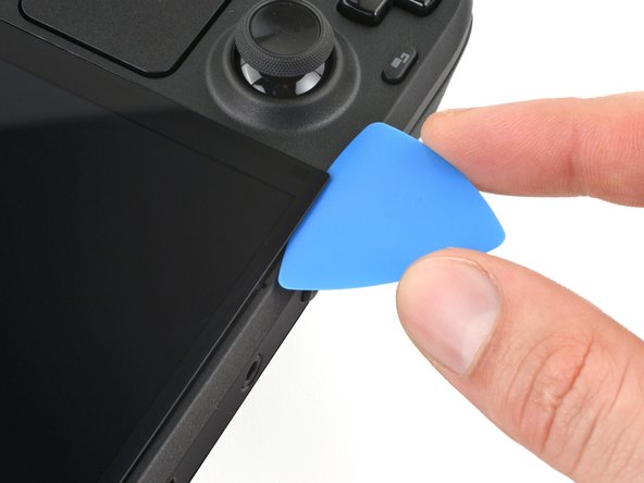
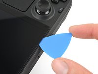
Pull up on the suction handle with a strong, steady force to create a gap between the screen and the frame.
-
Insert the tip of an opening pick into the gap.
-
-
-
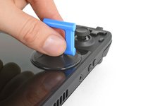
Pull up on the nub on the back of the suction handle to remove it from the screen.
-
-
-
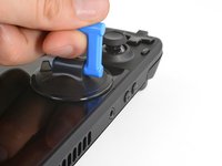
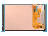
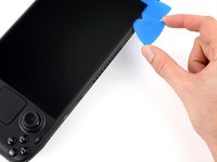
Along the top and bottom edges, don't insert your pick deeper than 3 mm (~1/8 of an inch) to avoid damaging the sensors, sensors cable, or screen cable.
-
Along the left and right edges, don't insert your pick deeper than 5 mm (~1/5 of an inch) to avoid damaging the screen panel.
-
-
-
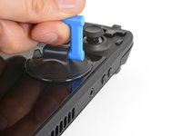
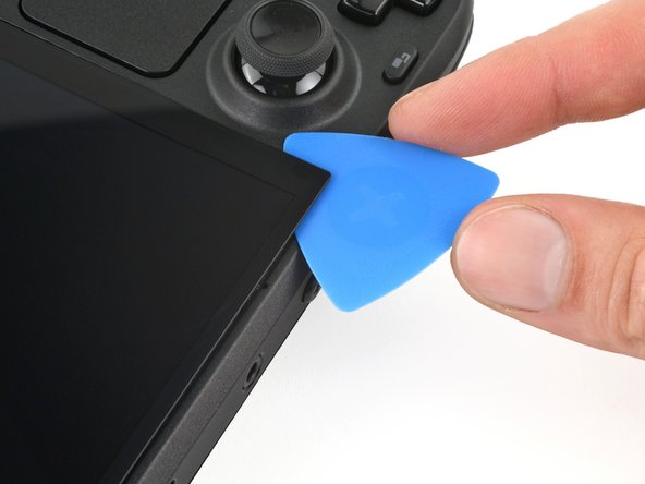
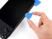
Rotate the pick so its flat edge is between the screen and frame.
-
Leave this pick inserted to prevent the adhesive from resealing.
-
-
-
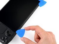
Insert another pick in the top left corner.
-
Slide the pick toward the power button to separate the adhesive securing the top edge of the screen.
-
-
-
Rotate the pick so its flat edge is between the screen and frame.
-
Leave this pick inserted to prevent the adhesive from resealing.
-
-
-
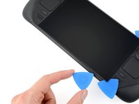
Heat the right edge of the screen for one minute.
-
-
-
Insert another pick just below the right thumbstick.
-
Slide the pick to the bottom right corner to separate the right edge adhesive.
-
Leave the pick inserted to prevent the adhesive from resealing.
-
-
-
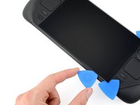
Heat the bottom edge of the screen for one minute.
-
-
-
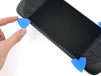
Insert another pick in bottom right corner along the bottom edge.
-
Slide the pick to the bottom left corner to separate the bottom edge adhesive.
-
Leave the pick inserted to prevent the adhesive from resealing.
-
-
-
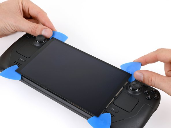
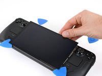
Grip the two picks along the top edge.
-
Pry up to lift the top edge of the screen away from the frame until you can grab it.
-
-
-
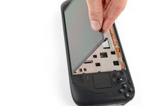
Flip the screen over the bottom edge of the frame.
-
Prop up the screen with a small box or book roughly 2.5 cm (~1 inch) thick.
-
-
-
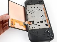
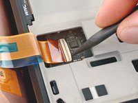
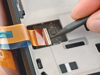
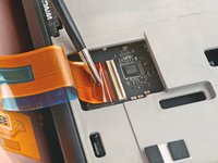
Use the point of a spudger or a clean fingernail to flip up the locking flap on the outside edge of the screen ZIF connector.
-
-
crwdns2935267:0crwdne2935267:0Tweezers$4.99
-
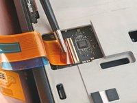
Use tweezers or your fingers to grip the screen cable pull tab and slide the cable straight out of its socket to disconnect it.
-
-
-
Remove the screen.
-
-
crwdns2935267:0crwdne2935267:0FixMat$31.41
-
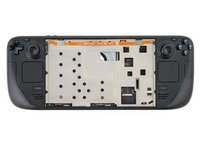
Use a T6 Torx driver to remove the eight 5.8 mm‑long screws securing the back cover.
-
-
-
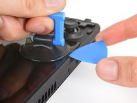
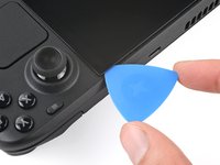
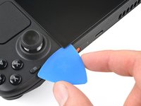
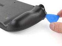
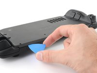
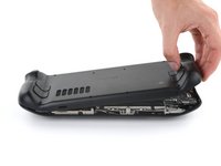
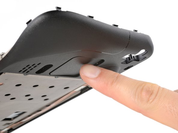
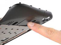
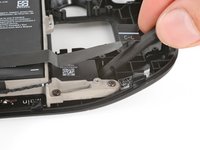
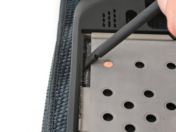
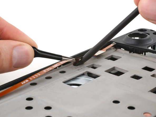
Insert an opening pick at an upward angle between the back cover and the front shell near one of the triggers.
-
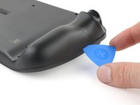
Slide your pick along the edge of the handle to release the clips securing it to the front shell.
-
-
-
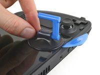
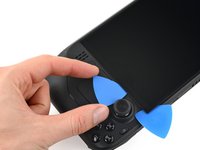
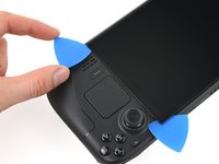
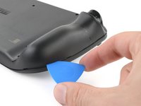
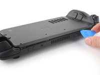
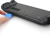
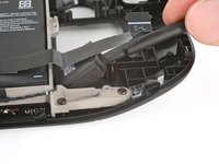
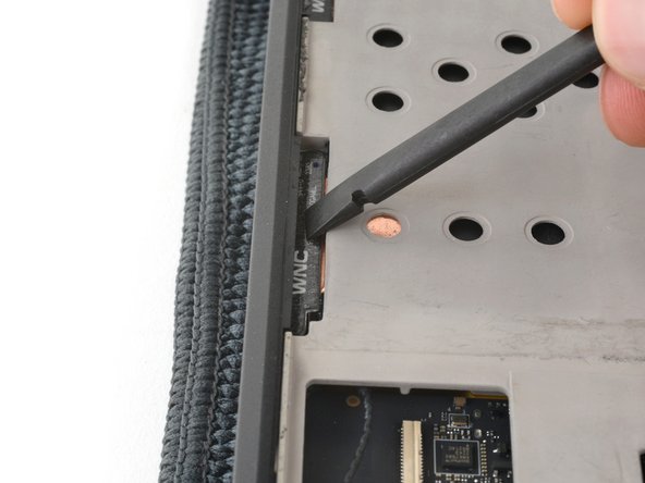
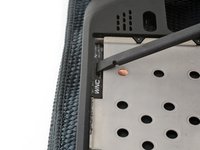
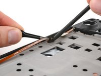
Reinsert your pick and slide it along the top and bottom edges until the back cover feels loose.
-
-
-
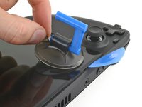
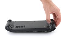
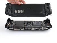
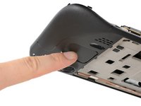
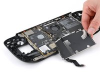
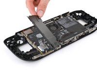
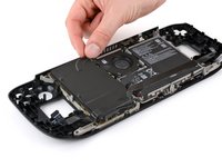
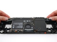
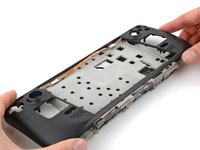
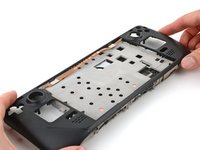
Grip the unclipped handle and pull it away from the front shell to release the remaining clips.
-
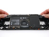
Remove the back cover.
-
-
-
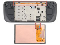
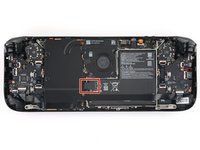
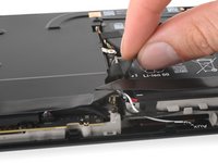
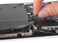
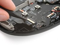
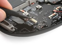
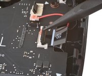
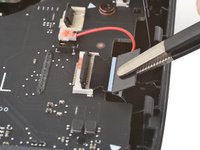
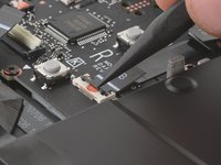
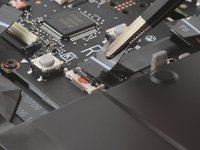
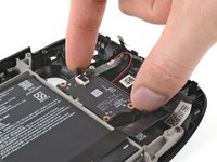
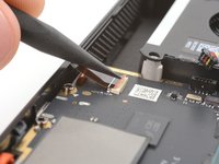
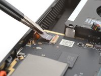
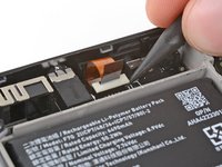
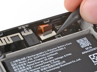
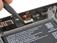
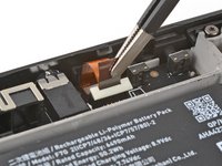
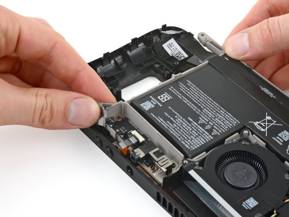
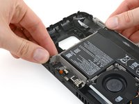
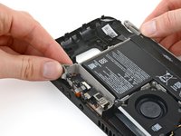
Grip the battery cable pull tab, located to the left of the battery.
-
Firmly pull the battery cable straight away from the motherboard shield (toward the battery) to disconnect it.
The pull tab can come off revealing the wires. The instructions should be updated to reflect that catch.
Hallo,
gibt es die Abschirmung auch als Ersatzteil irgendwo zu kaufen?
Danke
Bad step. Remove the shield plate from the next step first then safely disconnect the battery. Using this type of pull force here made the pull tab peel away exposing the wires.
-
-
-
During disassembly, skip the next three steps.
-
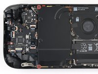
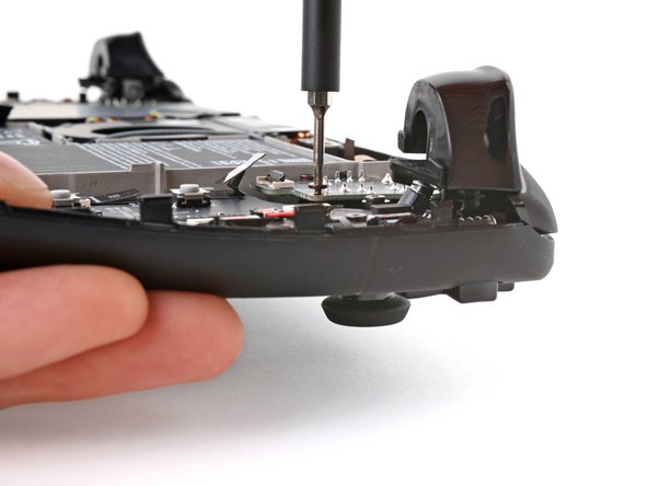
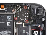
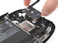
Reinstall the two 3.8 mm‑long screws to secure the motherboard shield.
-
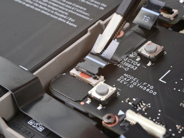
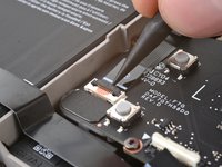
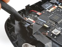
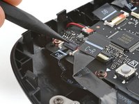
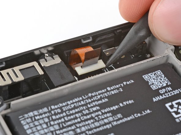
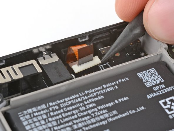
Reconnect the interconnect cable ZIF connector.
-
-
-
Use the flat end of a spudger to slide the battery connector into its socket on the motherboard.
-
-
-
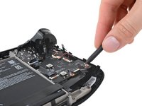
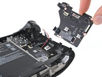
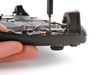
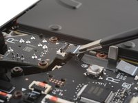
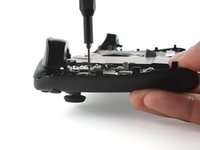
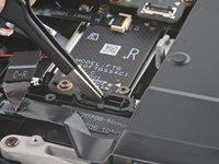
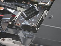
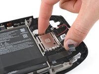
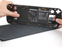
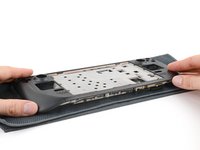
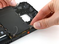
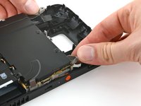
Use your T6 Torx driver to remove the two 3.8 mm‑long screws securing the motherboard shield.
-
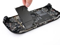
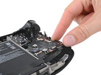
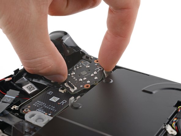
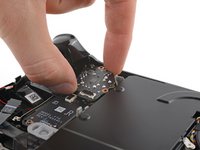
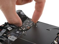
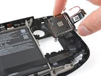
Lift the top edge of the motherboard shield up and flip it over the bottom edge of the frame, away from the motherboard.
The speaker cable is taped to the motherboard shield and the interconnect table is glued on top of the tape, so you can't just flip the shield over. You have to peel off the interconnect cable, unplug and peel off the speaker cable as well and then you can remove motherboard shield.
-
-
crwdns2935267:0crwdne2935267:0Tweezers$4.99
-
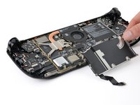
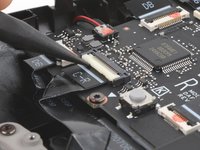
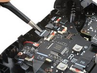
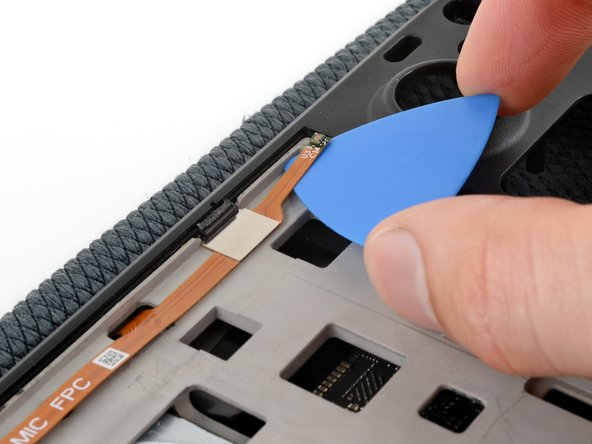
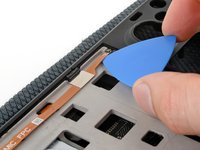
Use the point of a spudger to flip up the small locking flap on the left thumbstick ZIF connector.
-
Use tweezers or your fingers to grip the cable's pull tab and slide the connector straight out of its socket to disconnect it.
-
-
crwdns2935267:0crwdne2935267:0Tweezers$4.99
-
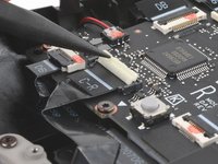
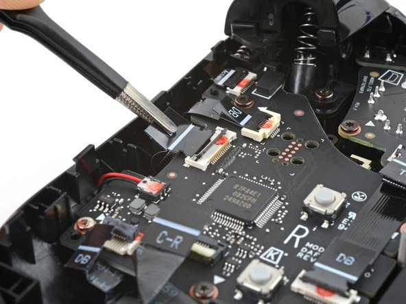
Use a spudger to flip up the small white locking flap on the left button board interconnect cable ZIF connector.
-
Use tweezers or your fingers to grip the cable's pull tab and slide it straight out of its socket to disconnect it.
-
-
-
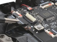
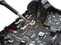
Flip up the small black locking flap on the left thumbstick cable ZIF connector.
-
Slide the connector straight out of its socket to disconnect it.
-
-
-
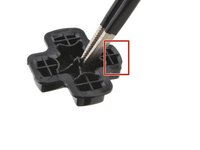
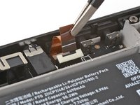
Flip up the small locking flap on the D‑pad ZIF connector, located in the top right corner.
-
The pull tab on this connector may be labeled DPAD.
-
Slide the connector straight out of its socket to disconnect it.
-
-
-
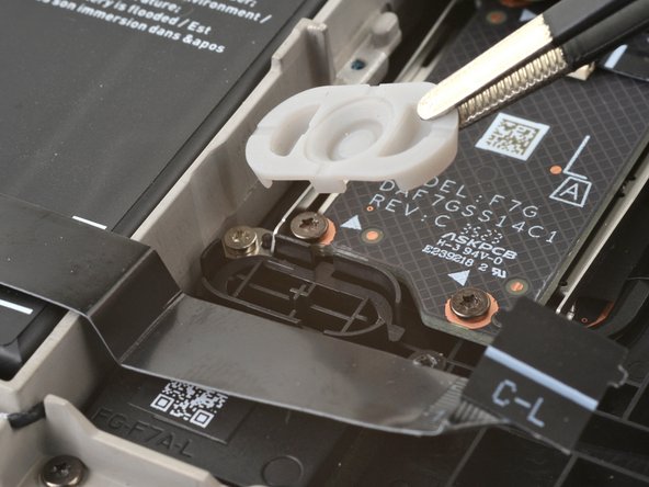
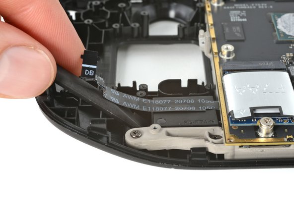
Flip up the small locking flap on the touchpad board cable ZIF connector, located just below the previous one.
-
Lift the connector until its arms are free and slide it straight out to disconnect it.
-
-
-
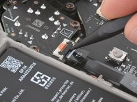
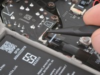
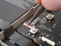
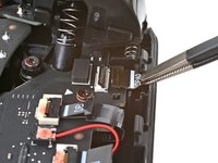
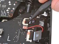
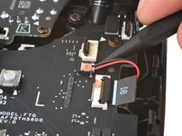
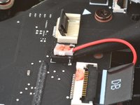
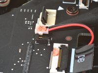
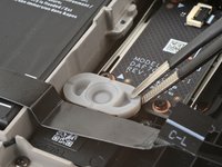
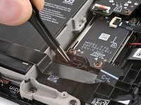
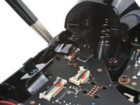
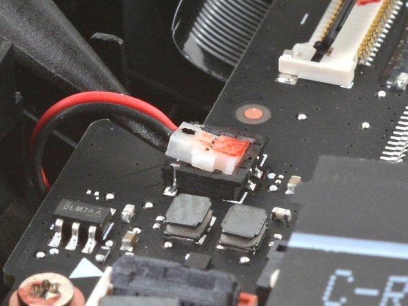
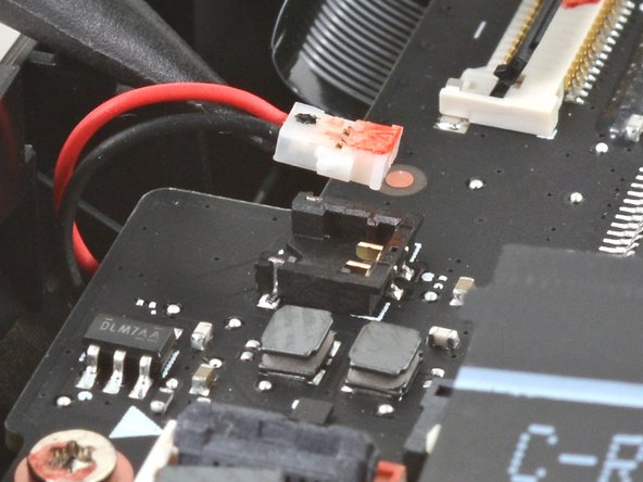
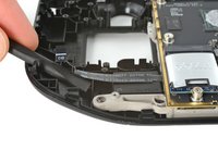
Insert the point of your spudger under the neck of the haptics cable connector.
-
Gently pry up to disconnect it.
Can I solder the haptic if the black box with the red and black cables still in tact?
-
-
-
-
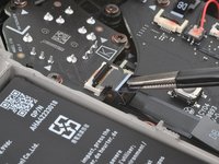
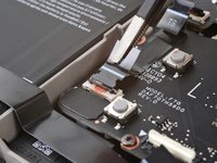
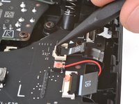
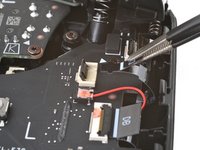
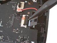
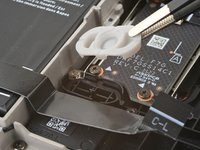
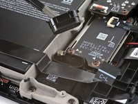
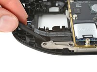
Flip up the small locking flap on the touchpad board cable ZIF connector, located just below the haptics connector.
-
Slide the connector straight out of its socket to disconnect it.
-
-
-
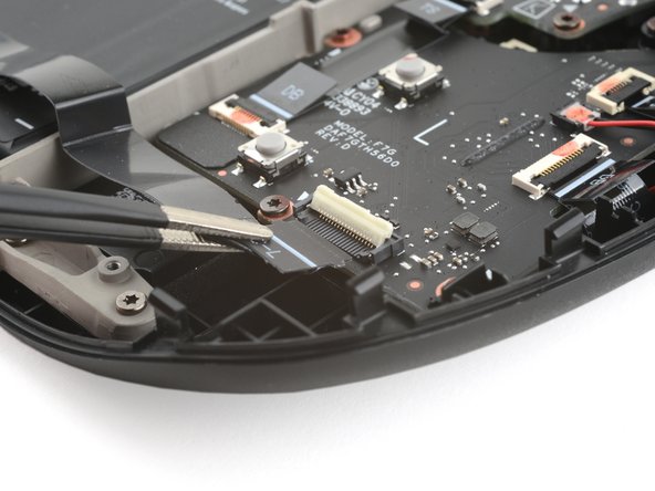
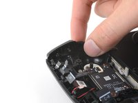
Use your T6 Torx driver to remove the four screws securing the left button board:
-
Two 5.9 mm‑long screws
-
One 3.8 mm‑long screw
-
One 4.9 mm‑long screw
-
-
-
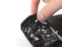
Insert the point of your spudger between the bottom right corner of the button board and the frame.
-
Pry up until you can grab the button board with your fingers.
-
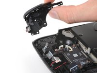
Remove the button board.
-
-
-
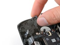
Use your T6 Torx driver to remove the three 5.9 mm‑long screws securing the right thumbstick.
-
-
-
Grip the edges of the thumbstick board and rotate it counterclockwise to clear the trigger.
-
Remove the thumbstick.
-
-
-
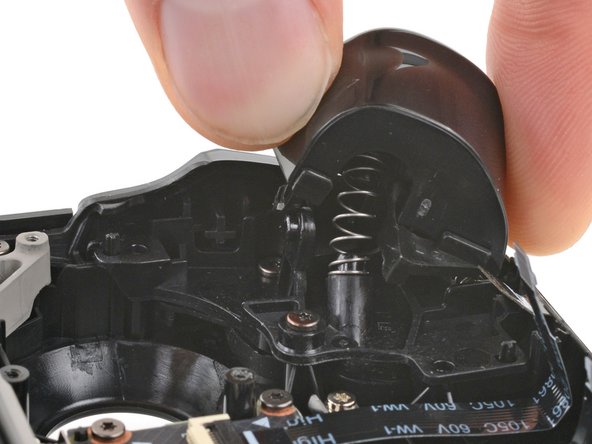
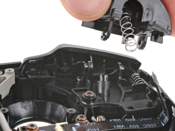
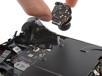
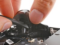
Place the flat end of a spudger onto the inside edge of the trigger's left clip.
-
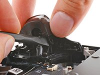
Use your fingers to push the trigger toward the left as you wedge the spudger between the clip and the peg.
-
Use your spudger to pivot the trigger clip out, away, and up from the peg to unlatch it.
-
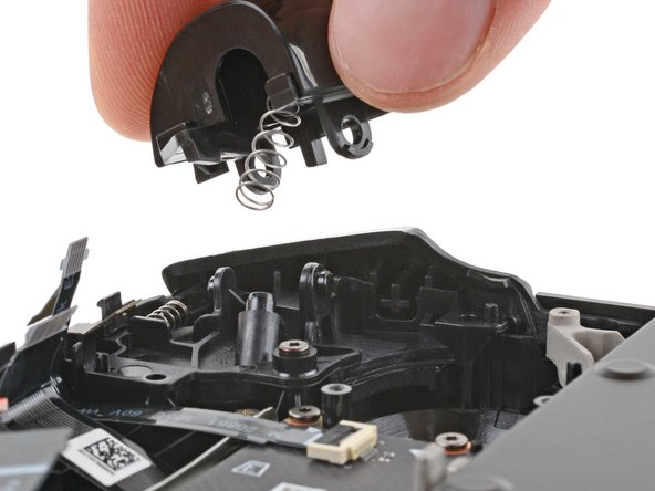
Check to make sure that the trigger spring is properly aligned. Test the trigger action before continuing reassembly.
-
-
-
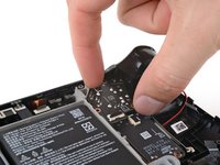
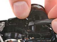
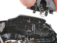
Use your T6 Torx driver to remove the three 5.9 mm‑long screws securing the left bumper assembly.
-
-
-
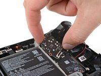
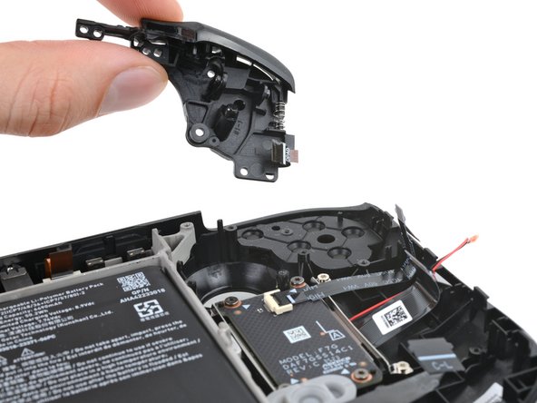
Grip the left arm of the bumper assembly and lift it off its alignment pegs.
-
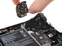
Slide the assembly to the left to clear the tab on the right edge of the frame.
-
Remove the assembly.
-
-
-
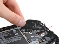
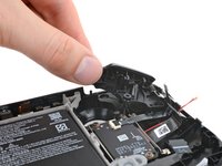
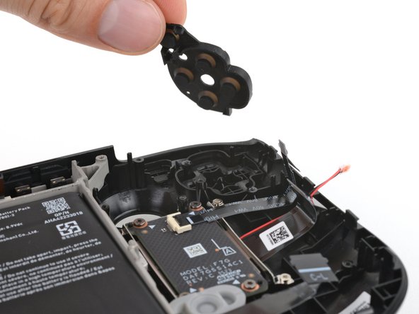
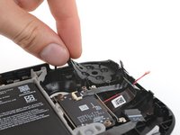
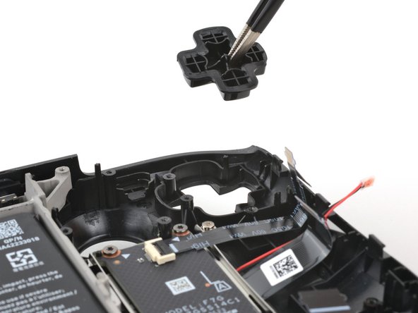
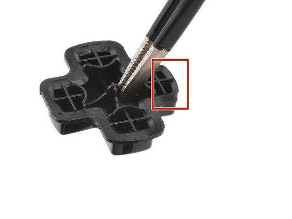
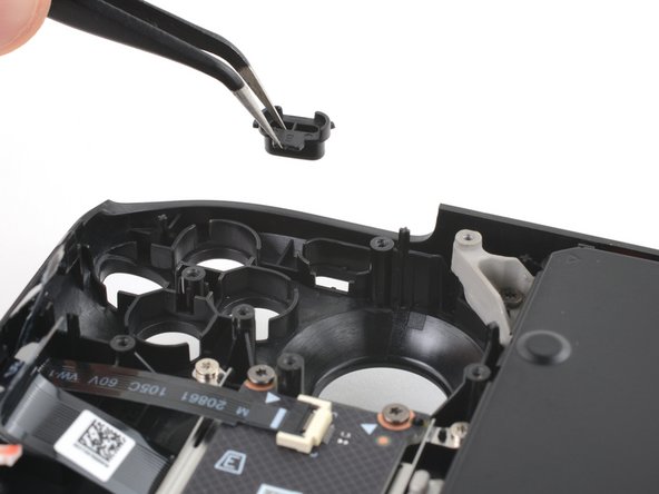
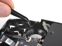
Remove the D-pad and view button membrane from the frame.
-
-
crwdns2935267:0crwdne2935267:0Tweezers$4.99
-
Use tweezers to remove the D-pad.
-
-
crwdns2935267:0crwdne2935267:0Tweezers$4.99
-
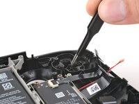
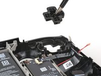
Use tweezers to remove the Steam button membrane.
-
-
-
Remove the Steam button.
-
-
crwdns2935267:0crwdne2935267:0Tweezers$4.99
-
Use the point of a spudger to flip up the small locking flap on the right thumbstick ZIF connector.
-
Use tweezers or your fingers to grip the cable's pull tab and slide the connector straight out of its socket to disconnect it.
-
-
crwdns2935267:0crwdne2935267:0Tweezers$4.99
-
Use a spudger to flip up the small white locking flap on the right button board interconnect cable ZIF connector.
-
Use tweezers or your fingers to grip the cable's pull tab and slide it straight out of its socket to disconnect it.
-
-
-
Flip up the small black locking flap on the right thumbstick cable ZIF connector.
-
Slide the connector straight out of its socket to disconnect it.
-
-
-
Flip up the small locking flap on the button board cable ZIF connector, located in the bottom left corner.
-
Slide the connector straight out of its socket to disconnect it.
-
-
-
Repeat the ZIF cable disconnection procedure for the remaining three ZIF connectors:
-
The touchpad cable
-
The touchpad board cable
-
The action buttons and menu button cable
-
-
-
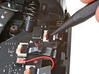
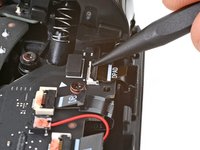
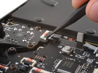
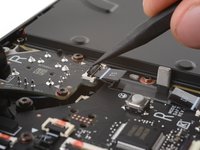
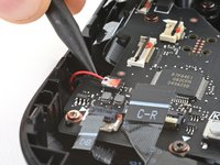
Insert the point of your spudger under the neck of the haptics cable connector.
-
Gently pry up to disconnect it.
-
-
-
Use your T6 Torx driver to remove the four screws securing the right button board:
-
Two 5.9 mm‑long screws
-
One 3.8 mm‑long screw
-
One 4.9 mm‑long screw
-
-
-
Insert the point of your spudger between the bottom left corner of the button board and the frame.
-
Pry up until you can grab the button board with your fingers.
-
Remove the button board.
-
-
-
Use your T6 Torx driver to remove the three 5.9 mm‑long screws securing the right thumbstick.
-
-
-
Grip the edges of the thumbstick board and rotate it clockwise to clear the trigger.
-
Remove the thumbstick.
-
-
-
Place the flat end of a spudger onto the inside edge of the trigger's right clip.
-
Use your fingers to push the trigger toward the right as you wedge the spudger between the clip and the peg.
-
Use your spudger to pivot the trigger clip out, away, and up from the peg to unlatch it.
-
Check to make sure that the trigger spring is properly aligned. Test the trigger action before continuing reassembly.
-
-
-
Use your T6 Torx driver to remove the three 5.9 mm‑long screws securing the right bumper assembly.
-
-
-
Grip the right arm of the bumper assembly and lift it off the alignment pegs.
-
Slide the assembly to the right to clear the tab on the left edge of the frame.
-
Remove the assembly.
-
-
-
Remove the action and menu buttons membrane from the frame.
-
-
crwdns2935267:0crwdne2935267:0Tweezers$4.99
-
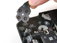
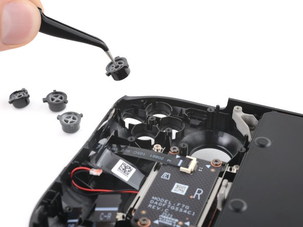
Use tweezers to remove the four action buttons, A, B, X, and Y.
-
-
crwdns2935267:0crwdne2935267:0Tweezers$4.99
-
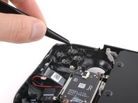
Use tweezers to remove the quick access button membrane.
-
-
-
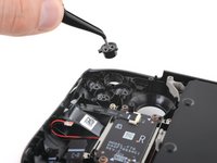
Use tweezers to remove the quick access button.
-
-
crwdns2935267:0crwdne2935267:0Tweezers$4.99
-
Use tweezers to remove the menu button.
-
-
-
Use tweezers to remove the view button.
-
-
-
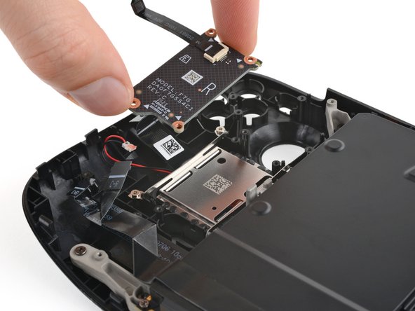
Use your T6 Torx driver to remove the four 5 mm‑long screws securing the right touchpad board.
-
-
-
Use your fingers to remove the right touchpad board.
-
-
-
Use your T6 Torx driver to remove the four 6 mm‑long screws securing the right touchpad.
-
-
-
Remove the right touchpad.
-
-
-
Use your T6 Torx driver to remove the four 5 mm‑long screws securing the left touchpad board.
-
-
-
Use your fingers to remove the left touchpad board.
-
-
-
Use your T6 Torx driver to remove the four 6 mm‑long screws securing the left touchpad.
-
-
-
Remove the left touchpad.
-
-
-
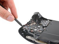
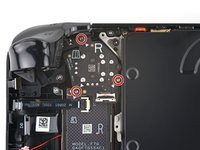
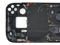
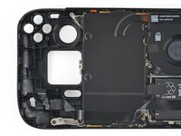
Use your T6 Torx driver to remove the two 3.8 mm‑long screws securing the top left and bottom left corners of the motherboard shield.
-
-
-
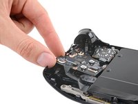
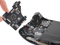
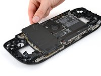
Lift the top edge of the motherboard shield up and flip it over to the right of the motherboard, over the battery.
-
-
-
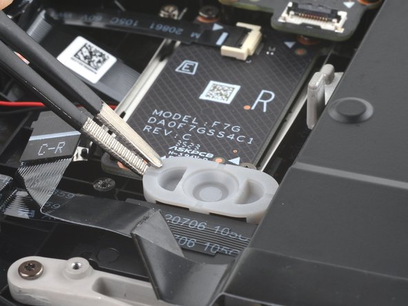
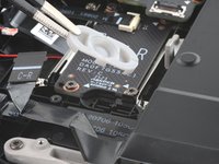
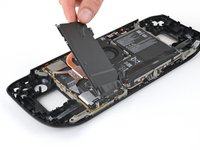
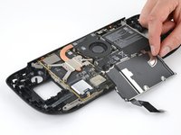
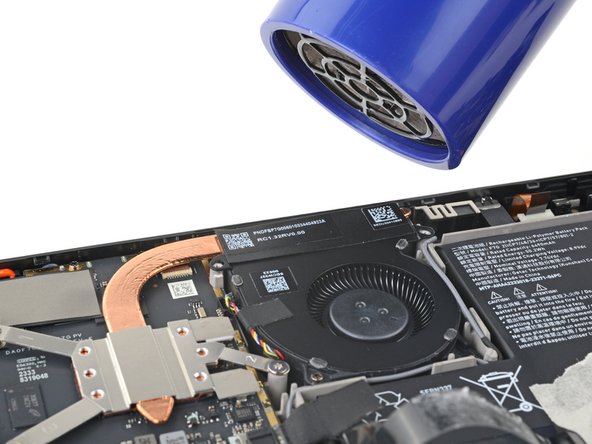
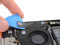
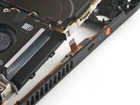
Use an iOpener or hair dryer to soften the adhesive on the black sticker connecting the heat sink to the fan.
-
-
-
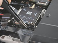
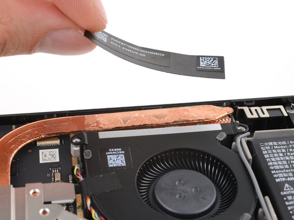
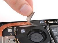
Slide the tip of an opening pick under one edge of the heat sink sticker.
-
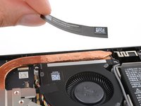
Peel the sticker up until you can grab it with your fingers.
-
Gently remove the sticker from the heat sink and fan.
-
-
-
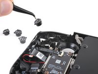
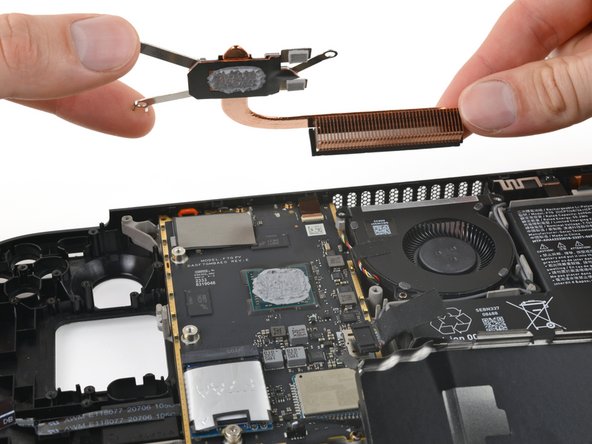
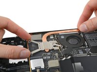
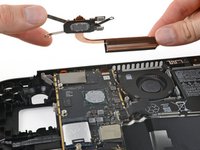
Use your T6 Torx driver to remove the three 3.3 mm‑long screws securing the heat sink.
-
-
-
Lift the heat sink from the motherboard and remove it.
-
-
-
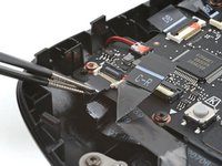
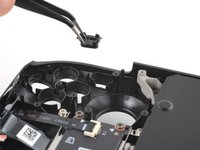
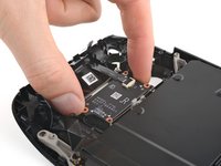
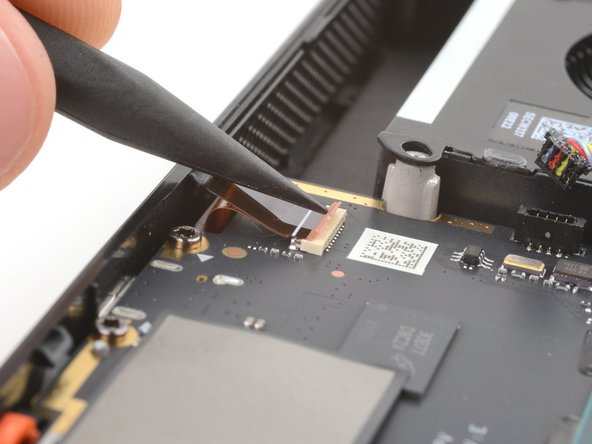
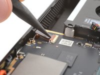
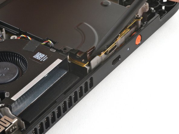
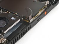
Use the point of your spudger to flip up the small locking flap on the audio board ZIF connector in the upper right corner of the motherboard.
-
Use tweezers or your fingers to grip the cable's pull tab and pull it straight out of its socket to disconnect it.
-
-
-
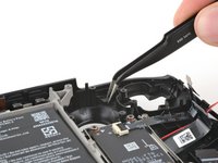
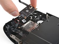
Use your fingers or a spudger to gently lift the white locking tab on the audio board socket to release the cable.
-
-
-
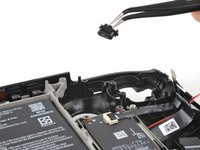
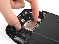
Use tweezers or your fingers to pull the audio board cable out of its socket to disconnect it.
-
-
-
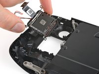
Insert the flat end of your spudger between the right speaker and the frame.
-
Slowly pry up the speaker to separate the adhesive securing it.
-
-
-
Insert the flat end of your spudger between the left speaker and the frame.
-
Slowly pry up the speaker to separate the adhesive securing it.
-
-
-
Place the motherboard shield back onto the motherboard to protect it during the rest of the repair.
-
-
-
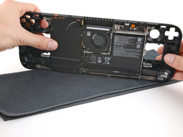
Lay a soft, clean cloth on your work surface.
-
While holding the motherboard shield in place, flip over your Steam Deck OLED and lay it screen-side-down onto the cloth.
-
-
-
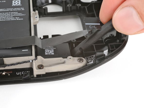
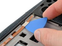
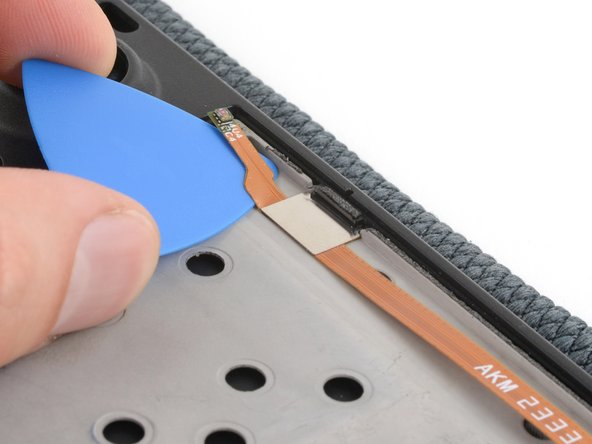
Insert the tip of an opening pick under the right-side ambient light sensor to separate it from the top right corner of the screen recess.
-
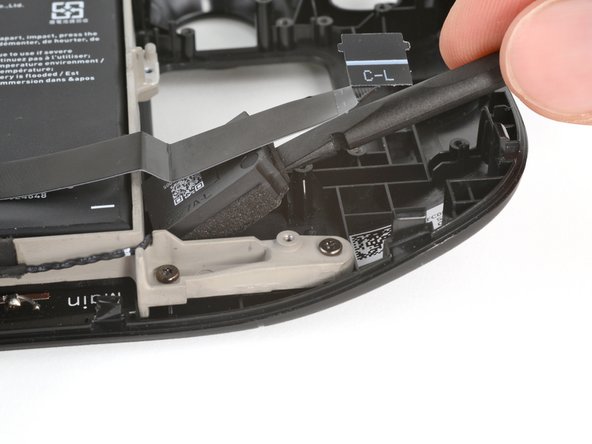
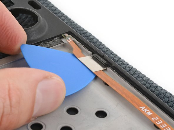
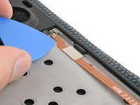
Lower your pick flat to the midframe and reinsert it under the metal tab located next to the ambient light sensor.
-
Slide your pick under the tab to separate it from the midframe.
-
-
-
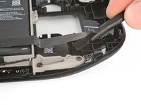
Repeat the previous step to separate the left-side ambient light sensor and metal tab.
-
-
-
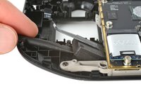
Press the flat end of your spudger or your fingers through the bottom left cutout in the screen recess and separate the antenna from the front shell.
-
Repeat for the antenna in the bottom middle of the screen recess.
-
-
-
Flip your Steam Deck OLED back over and lay it screen-side-down.
-
Use your T6 Torx driver to remove the six 5.9 mm‑long screws securing the midframe to the front shell.
-
-
-
Rotate the device so the power button is closest to you.
-
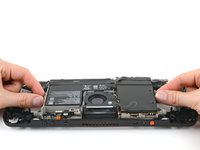
Grip the bottom arms of the midframe and brace your other fingers against the front shell.
-
Use your fingers to pry the bottom edge of the midframe away from the front shell.
-
-
-
Continue holding up the bottom right arm of the midframe with one hand.
-
With your other hand, pry the top edge of the front shell (near the volume buttons) away from the midframe.
-
Lift the top right corner of the midframe away from the front shell until the headphone jack comes free of its cutout.
-
-
-
Repeat the previous step for the top left corner of the midframe, prying the front shell (near the power button) away from the midframe as you lift the midframe about half an inch (~1.25 cm) up.
-
-
-
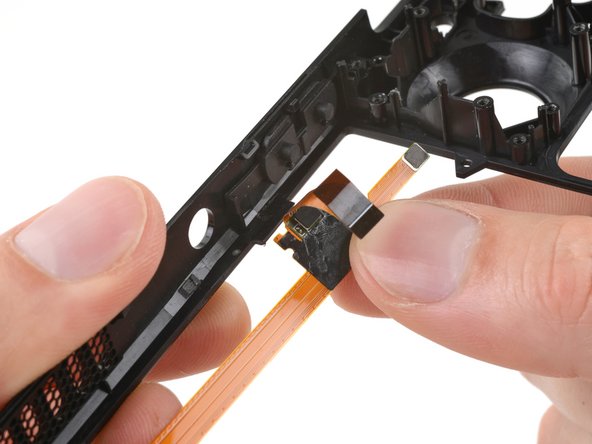
Insert the flat end of your spudger against the audio board cable in the cutout in the midframe.
-
Hold the cable's pull tab clear of the cutout and lift the midframe over the cable.
-
-
-
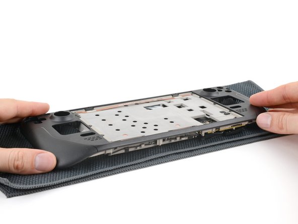
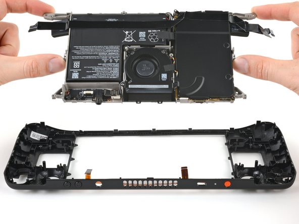
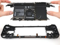
Remove the midframe.
-
-
-
Flip the midframe over, screen-side-up.
-
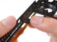
Hook the top edge of your replacement front shell over the top edge of the midframe, aligning the buttons and ports with their cutouts.
-
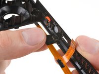
Grip the right end of the audio board cable and thread it through its cutout in the midframe and over the motherboard. Use a spudger or tweezers to angle the cable away from the midframe as you thread it.
-
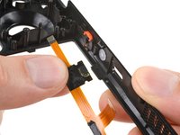
Ensure the left end of the audio board cable threads over the audio board and doesn't become trapped underneath.
-
-
-
Use your fingers to separate the metal tab securing the left-side ambient light sensor from the front shell.
-
-
-
Use your fingers to separate the metal tab securing the right-side ambient light sensor from the front shell.
-
-
-
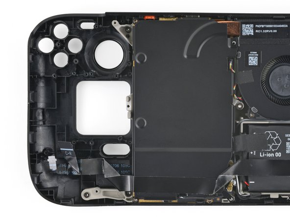
Remove the ambient light sensors and audio board cable.
-
All that remains is the front shell.
-


To reassemble your device, follow these instructions in reverse order.
Take your e-waste to an R2 or e-Stewards certified recycler.
Repair didn’t go as planned? Try some basic troubleshooting, or ask our Steam Deck OLED answers community for help.
To reassemble your device, follow these instructions in reverse order.
Take your e-waste to an R2 or e-Stewards certified recycler.
Repair didn’t go as planned? Try some basic troubleshooting, or ask our Steam Deck OLED answers community for help.
crwdns2935221:0crwdne2935221:0
crwdns2935229:03crwdne2935229:0

crwdns2915084:0crwdne2915084:0

Guide Team crwdns2935289:0Guide Teamcrwdne2935289:0
Staff
crwdns2931471:09crwdne2931471:0
crwdns2935297:013,423crwdne2935297:0
crwdns2947410:01crwdne2947410:0
Seems to be missing the break screen left side adhesive step. Good guide otherwise :)