crwdns2915892:0crwdne2915892:0
Follow this guide to remove and replace the logic board for the iPhone SE 2020.
Note: Each iPhone's logic board and Touch ID fingerprint sensor are paired at the factory, so replacing the logic board will disable Touch ID unless you also install a replacement home button that has been properly paired to your new logic board.
crwdns2942213:0crwdne2942213:0
-
-
Remove the two 3.5 mm pentalobe screws on the bottom edge of the iPhone.
-
-
-
Measure 3 mm from the tip and mark the opening pick with a permanent marker.
How to break your phone more like i probably just buy another one its not worth the hassle geometry dash 2.2
Person who doesn’t know how to read a ruler.
-
-
crwdns2935267:0crwdne2935267:0Clampy - Anti-Clamp$24.95
-
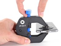
Pull the blue handle backwards to unlock the Anti-Clamp's arms.
-
Slide the arms over either the left or right edge of your iPhone.
-
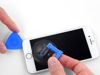
Position the suction cups near the bottom edge of the iPhone just above the home button—one on the front, and one on the back.
-
Squeeze the cups together to apply suction to the desired area.
Too bad that the instructions use equipment that are not sold with the repair kit that was supposed to be sufficient.
-
-
-
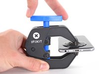
Pull the blue handle forwards to lock the arms.
-
Turn the handle clockwise 360 degrees or until the cups start to stretch.
-
Make sure the suction cups remain aligned with each other. If they begin to slip out of alignment, loosen the suction cups slightly and realign the arms.
-
-
-
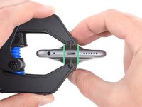
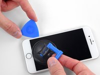
Heat an iOpener and thread it through the arms of the Anti-Clamp.
-
Fold the iOpener so it lays on the bottom edge of the iPhone.
-
Wait one minute to give the adhesive a chance to release and present an opening gap.
-
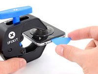
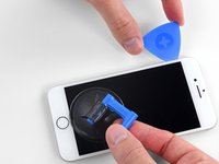
Insert an opening pick into the gap.
-
Skip the next three steps.
-
-
-
Heating the lower edge of the iPhone will help soften the adhesive securing the display, making it easier to open.
-
Use a hairdryer or prepare an iOpener and apply it to the lower edge of the phone for about 90 seconds in order to soften up the adhesive underneath.
-
-
-
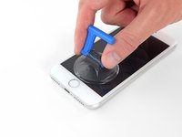
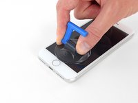
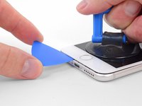
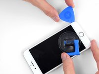
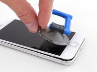
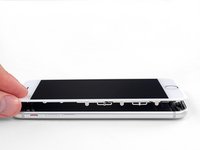
Apply a suction cup to the lower half of the front panel, just above the home button.
-
-
-
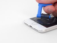
Pull up on the suction cup with firm, constant pressure to create a slight gap between the screen and the frame.
-
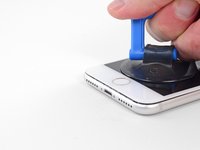
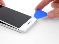
Insert an opening pick into the gap.
I bought a special tool from JerryRigEverything that is a thin, flat metal "knife." It easily made the first cut below the home button and then I used the blue plastic triangles with the 3mm marks to score around the rest of the edges. Careful, slow and patient wins the day here. Careful at the top. Don't just pull up on the screen, definitely push the screen down toward home button as there are a couple of "hooks" holding the screen to the body at the top of phone.
I used an electrician's heat gun for 90 seconds. Worked well. You don't have to pull up on the suction cup very much AT ALL. I bought a special tool from JerryRigEverything that is a thin, flat metal "knife." It easily made the first cut and then I used the blue plastic triangles with the 3mm marks to score around the rest of the edges. I did this in the exact order of the instructions and it worked well. Careful, slow and patient wins the day here. Careful at the top. Don't just lift up on the screen, definitely push the screen down toward home button as there are a couple of clips holding the screen to the body at the top of phone.
-
-
-
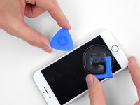
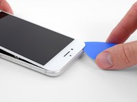
Slide the opening pick up the left edge of the phone starting at the lower edge and moving towards the volume control buttons and silent switch, breaking up the adhesive holding the display in place.
-
Stop near the top left corner of the display.
-
-
-
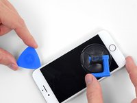
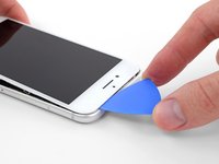
Re-insert your tool at the lower right corner of the iPhone, and slide it around the corner and up the right side of the phone to separate the adhesive.
-
-
-
Gently pull up on the suction cup to lift up the bottom edge of the display.
-
Pull on the small nub on the suction cup to remove it from the front panel.
-
-
-
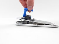
Slide an opening pick underneath the display around the top left corner and along the top edge of the phone to loosen the last of the adhesive.
-
-
-
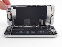
Slide the display assembly slightly down (away from the top edge of the phone) to disengage the clips holding it to the rear case.
-
-
-
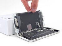
Open the iPhone by swinging the display up from the left side, like the back cover of a book.
-
Lean the display against something to keep it propped up while you're working on the phone.
-
-
-
crwdns2935267:0crwdne2935267:0Magnetic Project Mat$19.95
-
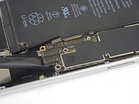
Remove four Phillips screws securing the lower display cable bracket to the logic board, of the following lengths:
-
Two 1.3 mm screws
-
Two 2.8 mm screws
-
Remove the bracket.
-
-
-
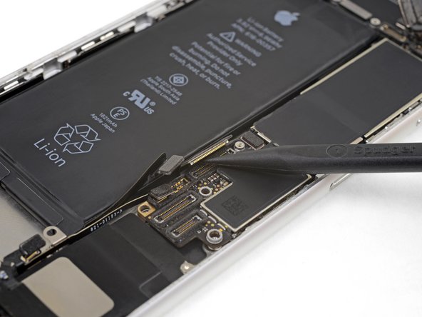
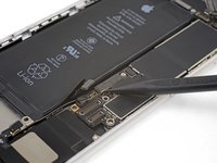
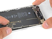
Use the point of a spudger to pry the battery connector out of its socket in the logic board.
-
Bend the battery connector cable slightly away from the logic board to prevent it from accidentally making contact with the socket and providing power to the phone during your repair.
-
-
-
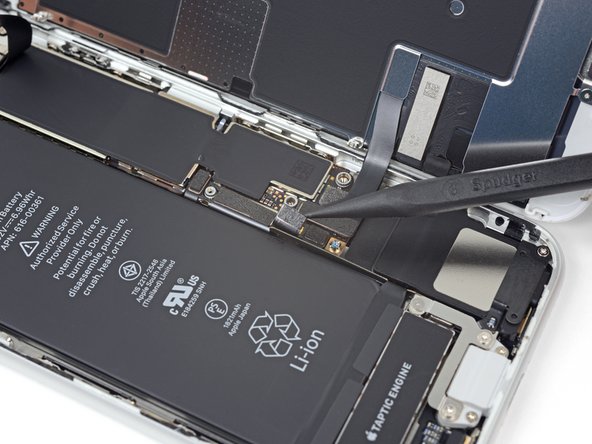
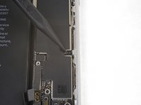
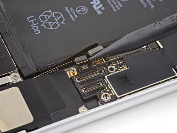
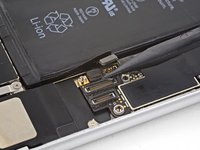
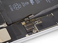
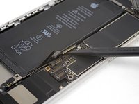
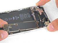
Use the point of a spudger to pry the lower display connector out of its socket.
-
-
-
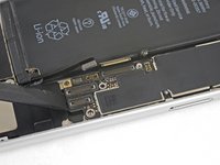
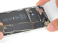
Use the point of a spudger to disconnect the second lower display cable.
-
-
-
Remove the three 1.3 mm Phillips screws securing the bracket over the front panel sensor assembly connector.
-
Remove the bracket.
The guide calls for a PH000, then the individual steps call for specific mm. Would be good to clarify at the beginning. I may also have missed it. :D
Habel -
-
-
-
Use the point of a spudger to disconnect the front panel sensor assembly connector.
-
-
-
Remove the display assembly.
Definitely skip step 18-28 and all the risks. Battery tape is easily removable by the following method
- use a tweezer to pull up a corner of each tape. Then use fingers to peel back all the black tab on top of battery
- use 2 hands. Index and thumb on both. Pull about 1/4” with one hand, then hold the tension and pull 1/4” with the other hand. Alternate, go slow. I was able to pull out all 4 tapes completely and battery was loose after that. I think the pause after each 1/4” while holding the stretched tape firmly prevents the tape from over stretching to become too thin and break.
- Don’t apply heat, I would guess that makes tape softer and break easier.
Have tried other methods and failed in the past. Pulling too fast (tape will snap) or use a tweezer to twist/roll (sharp edges will cut tape) Anyway, just use index/thumb on both hands and alternately pull slowly
-
-
-
Insert a SIM card eject tool, bit, or a straightened paperclip into the small hole in the SIM card tray.
-
Press to eject the tray.
-
-
-
Remove the SIM card tray from the iPhone.
-
-
-
Use the flat end of a spudger to disconnect the camera cable connector by prying it straight up from its socket.
-
-
crwdns2935267:0crwdne2935267:0Standoff Screwdriver for iPhones$5.49
-
Remove the two screws securing the rear-facing camera bracket:
-
One 3.0 mm standoff screw
-
One 3.1 mm Phillips screw
Dear iFixit - crew,
this very helpful manual ist great, but the picture is still, as Michael Millington stated earlier on, incorrect.
Could you please remove this faulty image and replace it?
“The screw and standoff are the other way round in this step. The photo shows the small screw removed and the standoff securing the logicboard is circled incorrectly. Also you may find that the standoff screw is not magnetic, making it a little tricky to replace!”
-
-
-
Remove the rear-facing camera bracket.
-
-
-
Use the point of a spudger to disconnect the flash connector from its socket by prying it straight up.
-
-
-
Remove the two screws securing the upper cable bracket:
-
One 2.9 mm Phillips screw
-
One 1.3 mm Phillips screw
-
-
-
Use the flat end of a spudger to pry the upper cable connector up from its socket.
-
-
-
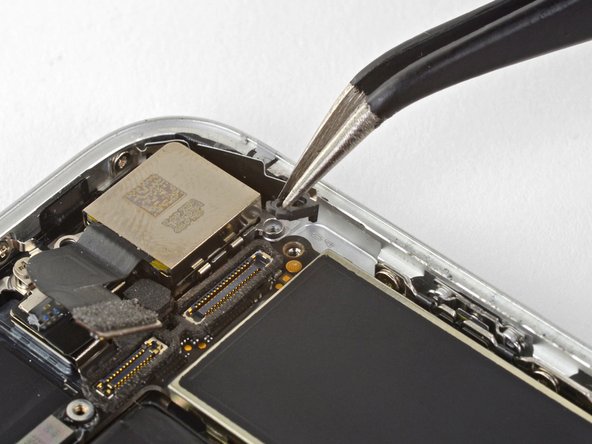
Remove the three Phillips 1.3 mm screws securing the top left antenna component.
-
-
-
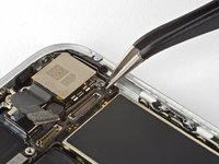
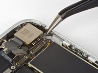
Remove the 1.4 mm Phillips screw securing the antenna component to the top of edge of the case.
-
-
-
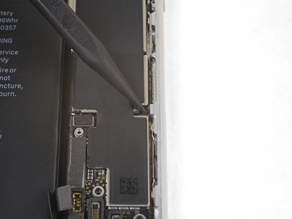
Remove the two Phillips screws securing the grounding clip at the top left edge of the logic board:
-
One 1.5 mm Phillips screw
-
One 2.6 mm Phillips screw
what happen if don't put this part?
what happen if don't put this part?
-
-
-
Remove the grounding clip.
Hi Albert,
It’s hard to tell. Most phone functions will probably work, but you may start getting quirky connectivity problems.
-
-
-
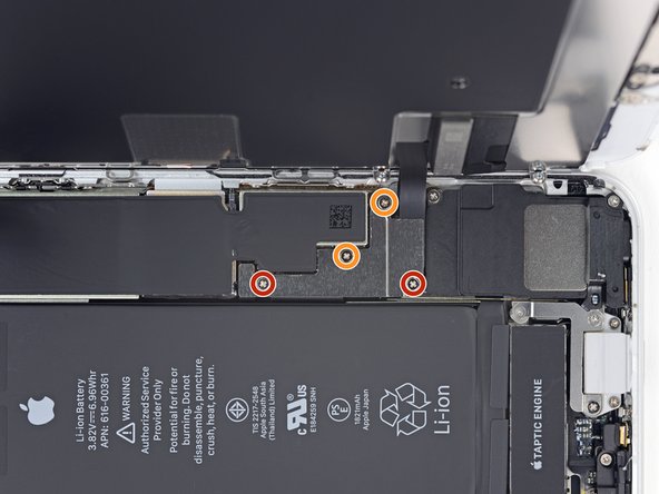
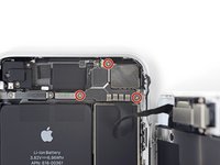
Remove the three screws securing the motherboard:
-
One 1.8 mm Phillips screw
-
One 2.5 mm standoff screw
-
One 2.2 mm standoff screw
They are just there for a last-ditch effort to keep water out of the connectors.
Duck -
Used a 2.0 mm flat screwdriver for the standoff screws
-
-
crwdns2935267:0crwdne2935267:0Tweezers$4.99
-
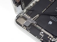
Use tweezers to gently bend the logic board grounding bracket out of the way.
-
-
-
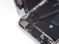
Use the point of a spudger to move the SIM card eject plunger out of the logic board's way.
"I will explain to you the summary in terms of explaining the work of a completely free fake email that is used in all the different services of all kinds and sites.
Also, registration in applications to other things that need to make a fake email ready to be used in a fake or temporarily instead of using the real mail.
By applying the following steps, you will have a fake e-mail ready, all you have to do is open any of the following links to the service to create an e-mail for you.
You can view the entire article here: https://wiki-mob.com/fake-email/
Source:https://wiki-mob.com/"
-
-
-
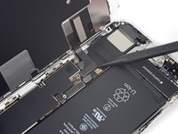
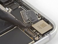
Use the point of a spudger to pry up and disconnect the Wi-Fi diversity antenna cable.
-
-
-
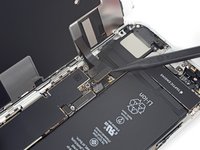
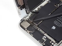
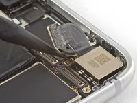
Use the point of a spudger to pry up and disconnect the Lightning cable connector.
-
-
-
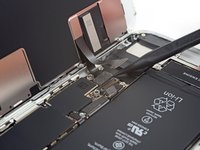
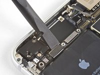
Use the point of a spudger to pry up and disconnect the wireless charging coil connector.
-
-
-
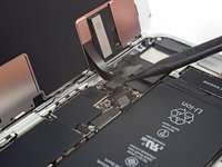
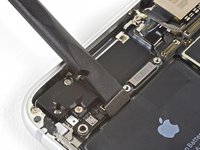
Use the flat end of a spudger to gently lift the battery connector end of the logic board up.
-
-
-
Grasping it by the edges, lift the logic board near the battery connector and remove it.
Etape 39 impossible quelque chose la retient
Bood ka ret keta na hi
-


To reassemble your device, follow the above steps in reverse order.
Take your e-waste to an R2 or e-Stewards certified recycler.
Repair didn’t go as planned? Check out our Answers community for troubleshooting help.
To reassemble your device, follow the above steps in reverse order.
Take your e-waste to an R2 or e-Stewards certified recycler.
Repair didn’t go as planned? Check out our Answers community for troubleshooting help.
crwdns2935221:0crwdne2935221:0
crwdns2935229:028crwdne2935229:0

This comment helped! It's the P2 bit.
Megolina -