crwdns2915892:0crwdne2915892:0
Follow this guide to remove or replace the logic board on an iPad Pro 9.7".
This guide is written with a cellular model iPad Pro. If your iPad is not the cellular enabled model, skip the first step.
For your safety, discharge the battery below 25% before disassembling your device. This reduces the risk of a dangerous thermal event if the battery is accidentally damaged during the repair. If your battery is swollen, take appropriate precautions.
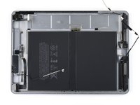
Some photos in this guide are from a different model and may contain slight visual discrepancies, but they won't affect the guide procedure.
crwdns2942213:0crwdne2942213:0
-
-
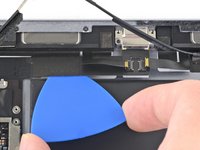
Insert a SIM card eject tool, bit, or a paperclip into the small hole in the SIM card tray, located near the bottom edge of the iPad.
-
Press firmly to eject the tray.
-
Remove the SIM tray.
-
-
-
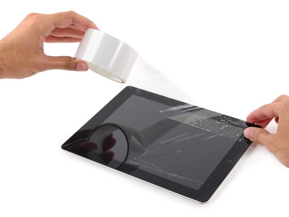
If your display glass is cracked, keep further breakage contained and prevent bodily harm during your repair by taping the glass.
-
Lay overlapping strips of clear packing tape over the iPad's display until the whole face is covered.
-
Do your best to follow the rest of the guide as described. However, once the glass is broken, it will likely continue to crack as you work, and you may need to use a metal prying tool to scoop the glass out.
Covering the screen with tape proved an essential safety step with the ipad display/lcd I just replaced. The screen was so badly broken that a part of it was almost powder, but the combination of the tape and sticky adhesive residue kept most of that together, and cleanup was pretty easy as a result. One caveat, though, is that the tape will probably make the suction cup useless for pulling up on the display. It did for me, anyway.
-
-
-
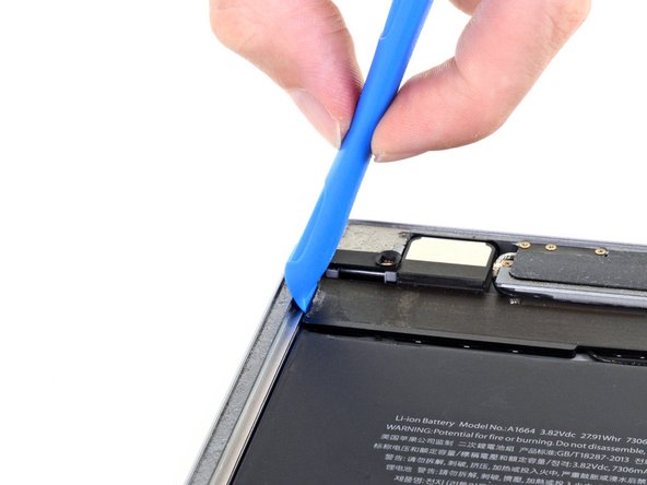
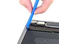
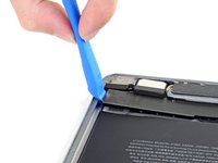
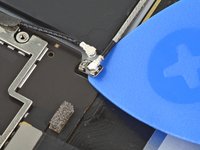
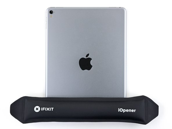
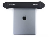
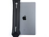
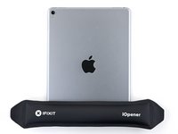
Handling it by the tabs on either end, place a heated iOpener over the top edge of the iPad.
-
Let the iOpener sit on the iPad for two minutes to soften the adhesive securing the front panel to the rest of the iPad.
I see a lot of videos that show using a heat gun on low to soften the adhesive. I know there is inherent risk with this since you could start delaminating things, but is it something that could be considered (at your own risk)? Or is it something that could have more risks than I am realizing?
Yes, you can definitely use a hair dryer, heat gun, or a heating pad. If you're using a heat gun, be careful not to overheat the display. The surface should feel slightly too hot to the touch.
-
-
-
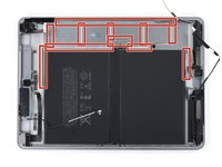
As you follow the directions, take special care to avoid prying in the following areas:
-
Home Button
-
Front Facing Camera
-
Main Camera
Verwirrend: Es sollte heissen, dass man an den beschriebenen Stellen eben NICHT hebeln sollte.
Danke! Ich habe den Teil mit dem NICHT hebeln nochmal hervorgehoben.
The screen cable is on the right side at the bottom. Be super careful not to slice too deeply there
-
-
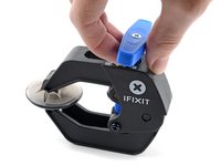
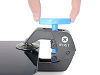
crwdns2935267:0crwdne2935267:0Clampy - Anti-Clamp$24.95
-
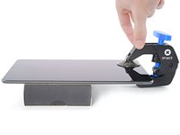
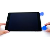
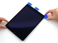
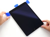
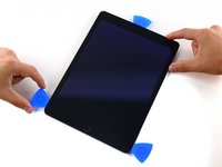
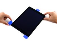
Elevate the iPad enough for the Anti-Clamp's arms to rest above and below the screen.
-
Pull the blue handle towards the hinge to disengage opening mode.
-
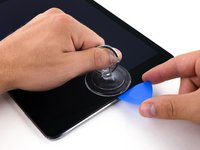
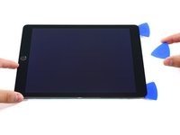
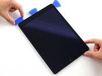
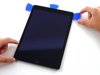
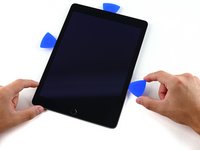
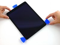
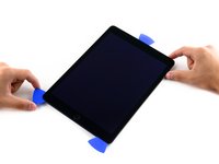
Position the suction cups near the top edge of the iPad—one on the front, and one on the back.
-
Push down on the cups to apply suction to the desired area.
-
-
-
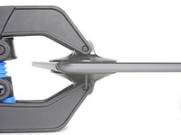
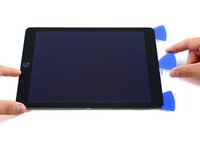
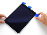
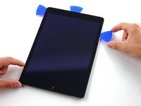
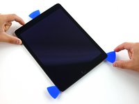
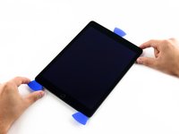
Push the blue handle away from the hinge to engage opening mode.
-
Turn the handle clockwise until you see the cups start to stretch.
-
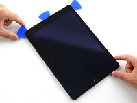
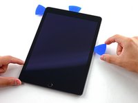
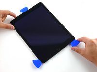
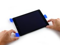
Wait one minute to give the adhesive a chance to release and present an opening gap.
-
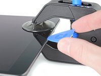
Insert an opening pick under the screen when the Anti-Clamp creates a large enough gap.
-
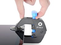
Skip the next two steps.
Do not use the anti clamp beyond this step. Doing so will run the risk of putting pressure on the screen and cracking it. Only use it for the initial opening of the device.
-
-
-
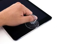
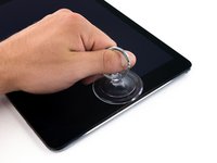
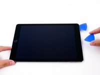
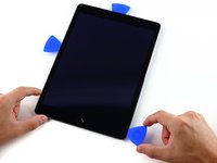
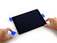
Place a suction cup over the iPad's front-facing camera and press down to create a seal.
The dangerous place with ribbon cables is in the lower right corner. There is a cable at the edge, so insert the pick carefully. Or rather, the correct answer is not to put a pick up to 5 cm from the bottom right. Other than that, there are no other dangerous places.
-
-
-
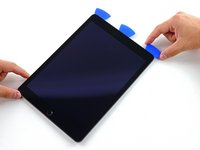
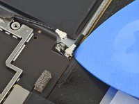
Firmly pull up on the suction cup to create a small gap between the front panel and the rear case.
-
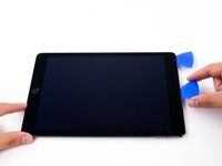
Once you've opened a sufficient gap, insert an opening pick into the gap to prevent the adhesive from resealing.
-
-
-
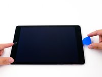
Slide the pick along the edge of the display, towards the headphone jack.
-
If there is still a considerable amount of resistance when sliding the opening pick, repeat the iOpener heating procedure and apply additional heat.
-
-
-
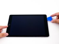
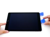
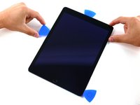
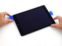
Insert a second opening pick by the front-facing camera.
-
-
-
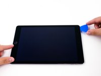
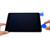
Slide the second pick along the top edge of the iPad, towards the Sleep/Wake Button.
-
-
-
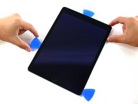
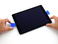
Insert a third pick by the front-facing camera.
-
-
-
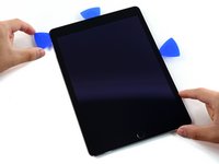
Bring the right opening pick down and around the top right corner of the iPad.
-
-
-
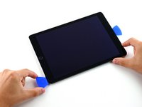
Bring the left opening pick around the top left corner of the tablet.
-
-
-
Reheat the iOpener and lay it over the right edge of the display to loosen the adhesive underneath.
-
-
-
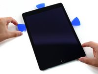
Slide the right opening pick roughly halfway down the display.
-
-
-
Reheat the iOpener and apply heat to the left side of the iPad.
-
-
-
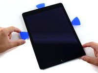
Slide the left-hand opening pick about halfway down the edge of the display.
-
-
-
Slide the opposite opening pick down to the bottom right corner of the iPad.
The screen cable is on the right side at the bottom. Be super careful not to slice too deeply there
Why is the first half of this the iPad Pro 9.7in and then from home button on it’s a 10.5in pro I think. But I know for sure that’s not 9.7 in the second half
-
-
-
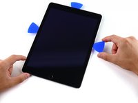
Slide the left-hand opening pick down the edge of the display until you reach the corner.
The screen cable is on the right side at the bottom. Be super careful not to slice too deeply there
-
-
-
Use the iOpener to apply heat to the bottom edge of the iPad.
You should avoid inserting the pick into the lower right corner as much as possible. The cable is nearby.
-
-
-
Bring the right-hand opening pick around the bottom corner of the iPad.
-
-
-
Remove the right-hand opening pick at the bottom of the iPad.
-
-
-
Slide the left-hand opening pick along the bottom edge of the display, then remove it from the bottom right corner of the iPad.
-
-
-
Use picks to ensure most of the adhesive has been cut through on the top, left, and bottom sides.
-
Twist the top and bottom picks to separate the display assembly from the rear case.
-
-
-
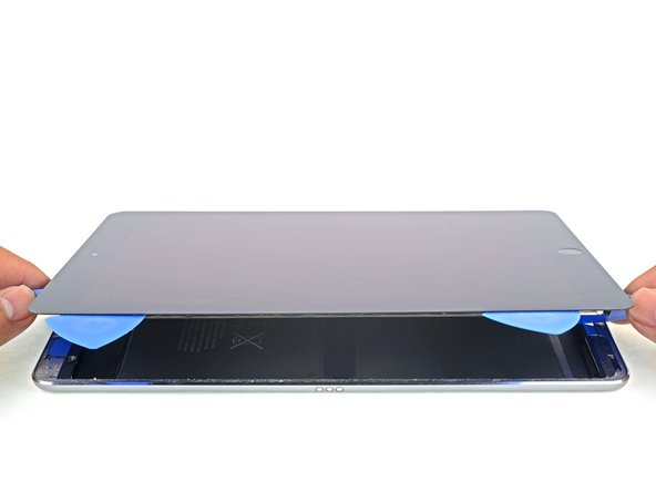
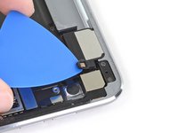
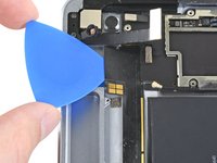
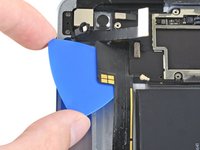
Swing the display assembly towards the right of the case, using the right edge as a hinge.
-
As you move the display assembly, make sure that the display ribbon cable is not being stressed.
-
Continue swinging the display assembly until it lays flat next to the rear case.
-
-
-
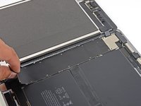
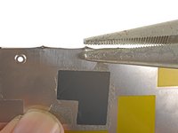
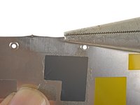
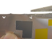
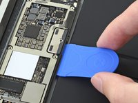
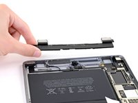
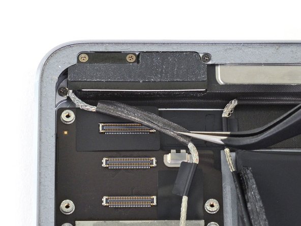
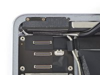
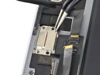
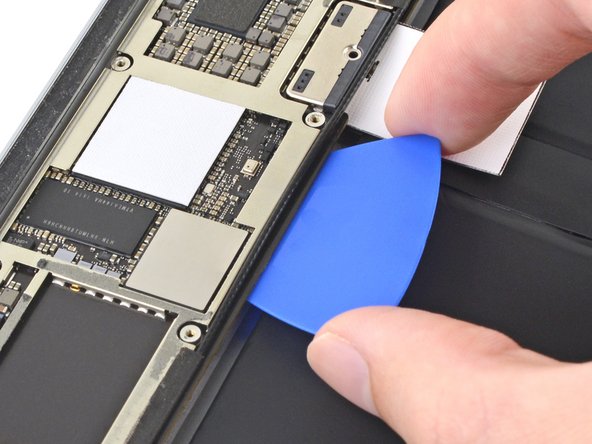
Use a Phillips screwdriver to remove the eleven 1.3 mm screws securing the EMI shield.
-
-
-
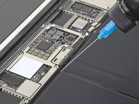
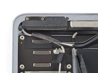
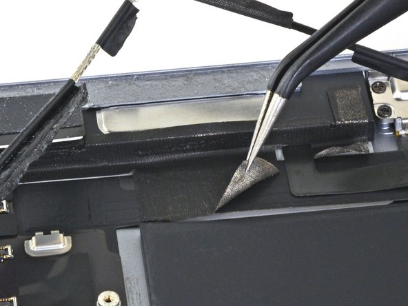
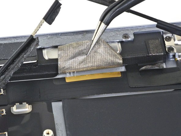
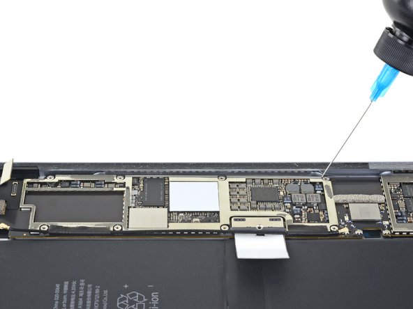
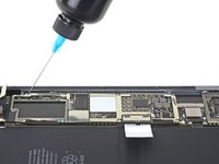
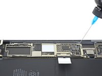
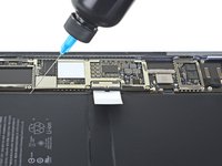
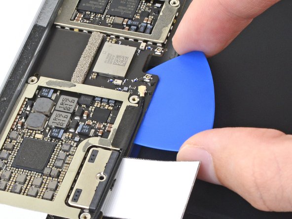
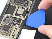
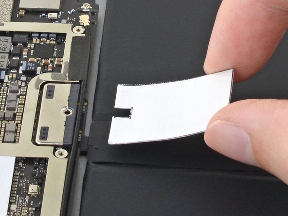
Apply a heated iOpener to the EMI shield on the logic board for one minute.
-
-
-
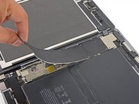
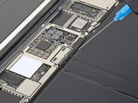
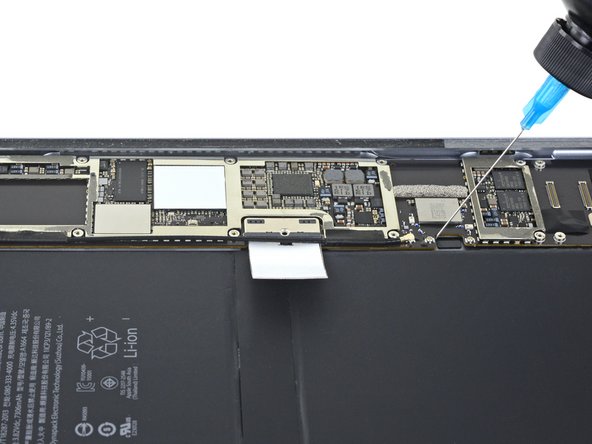
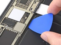
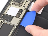
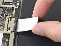
Lift the logic board EMI shield, starting at the edge nearest the top of the iPad.
-
Slowly peel the EMI shield up from the logic board.
-
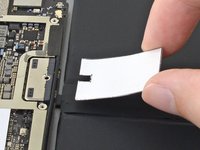
Remove the logic board EMI shield.
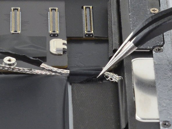
Don't peel the cover as shown from a short side. Lift the long side to avoid creasing the cover so much. This way it will lie flat when you reassemble it and not look so ugly. Also, you won't have to straighten so many creases with pliers
-
-
-
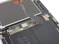
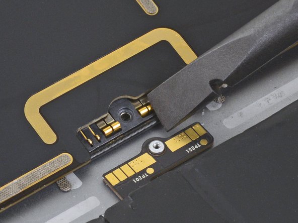
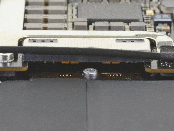
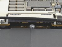
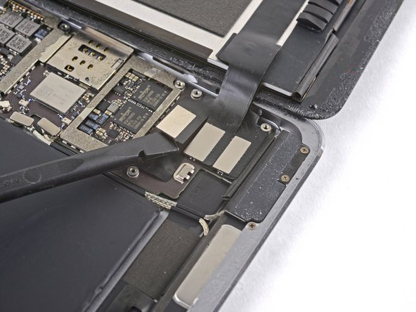
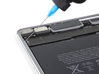
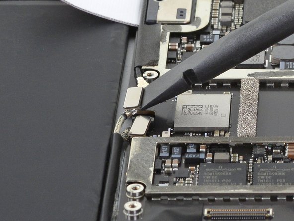
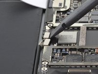
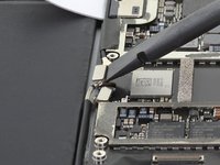
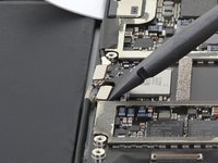
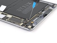
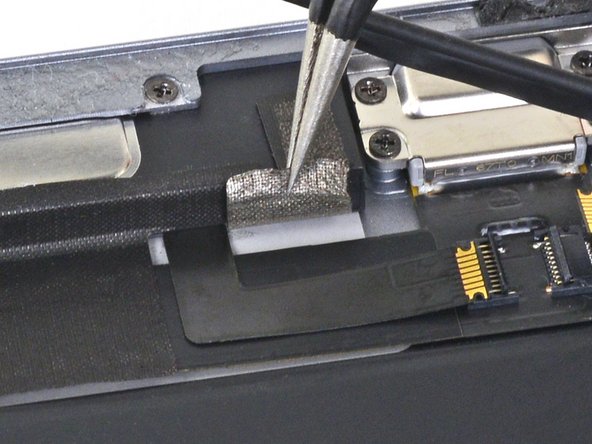
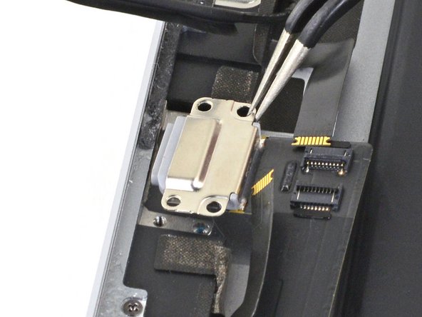
Use a Phillips driver to remove the 1.7 mm-long screw securing the battery connector.
What size is this screw?
i get 1.65mm with my calipers but the 1.3s read 1.25 on my calipers too, so probably a 1.7mm
-
-
-
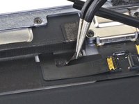
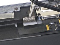
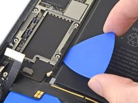
Squeeze the sharp protrusion with a pair of pliers to flatten it.
-
Repeat the process for all sharp protrusions along the edges of the EMI shield.
Don't peel the cover as shown from a short side. Lift the long side to avoid creasing the cover so much. This way it will lie flat when you reassemble it and not look so ugly.
-
-
Le connecteur de batterie est il réparable si abîmé ?
If the connector broken on the battery side is from an old battery to be replaced, there is no problem if it breaks. I think breaking means tearing the loop, but it's impossible to repair it. However, if you plug it in and screw in the screw, it can be used as a connector for the time being.
-
-
-
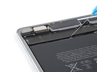
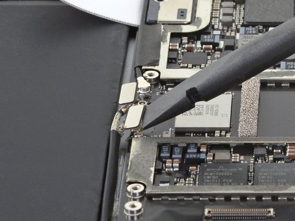
Slide the battery blocker underneath the left side of the logic board's battery connector at a 35 degree angle.
-
Leave the battery blocker in place as you work.
le connecteur de la batterie est t’il remplaçable ou repérable si jamais abîmé ?
Si le connecteur est abîmé, Il n'est ni remplaçable ni réparable, je crois. Donc, il faut lever le carte logique suffisamment pour enlever ou le mettre le connecteur de la batterie.
-
-
-
Apply a few drops of high-concentration (90% or higher) isopropyl alcohol under the logic board to the left and right of the battery connection.
-
Wait one minute for the isopropyl alcohol to weaken the adhesive under the logic board.
-
Try to insert the battery blocker. If the logic board doesn't easily lift up, apply a few more drops of isopropyl alcohol.
-
-
-
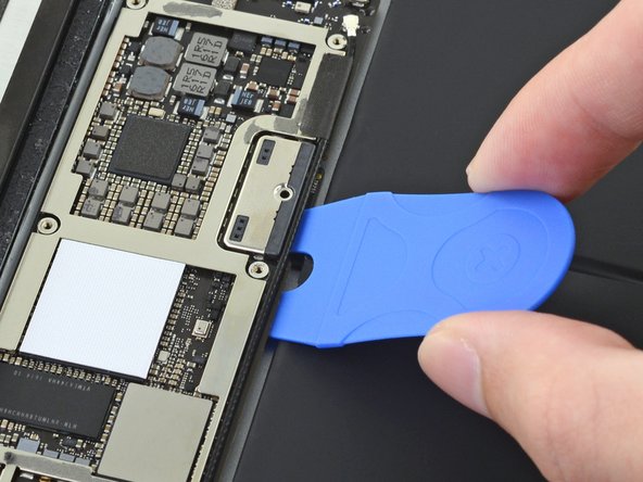
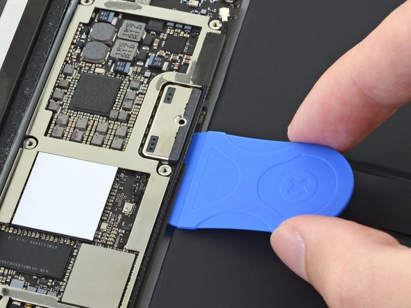
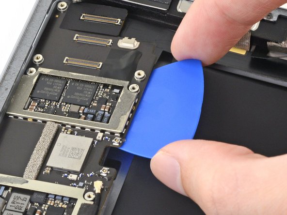
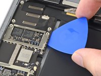
Use a Phillips screwdriver to remove the three 1.3 mm Phillips screws securing the display cable bracket.
i think we need to talk about the battery situation here. apple change up the style of battery connector on this model as well as some others. if someone can add to this list and add the appropriate photos in the right spot should help someone else. the battery tabs are open towards the battery side and inserting a tool in this area can pry them open further and damage or rip off the tab. some have found that by lifting on either side of the battery tab, they would not even encounter the tabs.
This operation shuld be doen before 30th step, so that it's more easy to remove EMI shield.
-
-
-
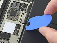
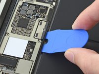
Remove the display cable bracket.
A tab was folded over a connector of some sort on the bottom side. I found it was a better to pull from the top to the bottom to fold the tabs slightly to remove this cover.
Actually it helps to move the cover slightly towards the bottom of the iPad as that disengages to tabs…
-
-
-
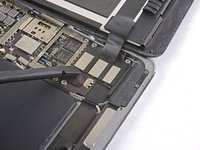
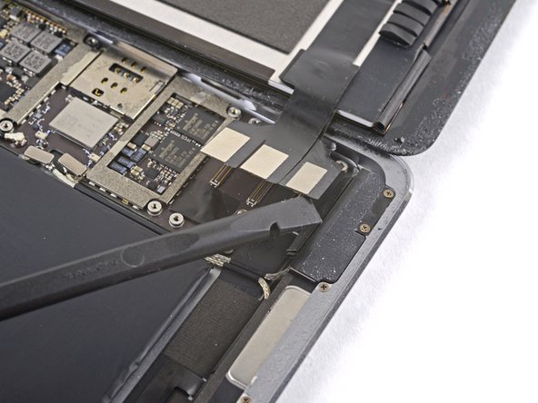
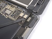
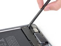
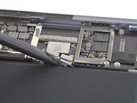
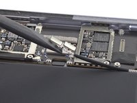
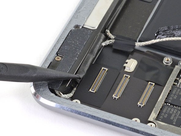
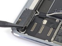
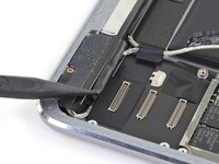
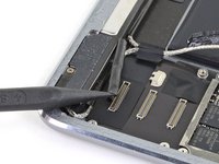
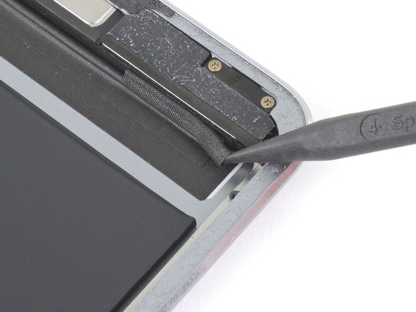
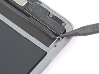
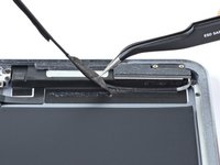
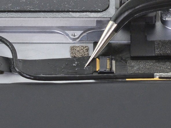
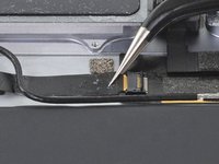
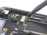
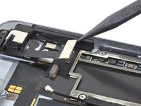
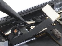
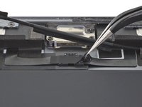
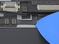
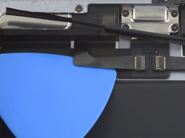
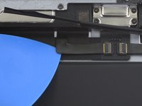
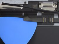
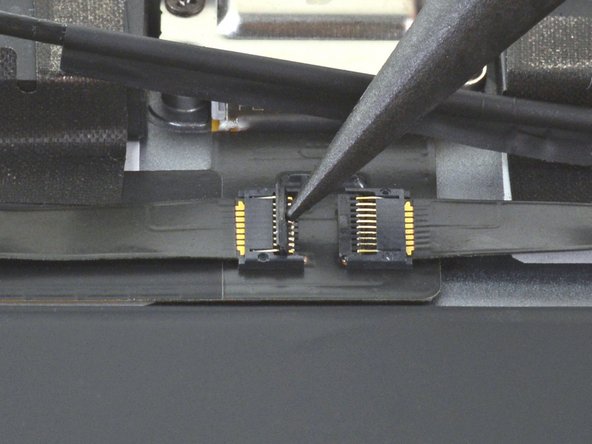
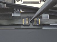
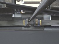
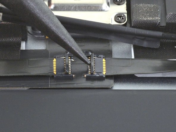
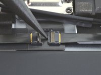
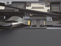
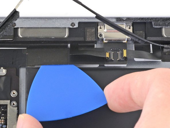
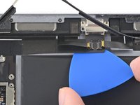
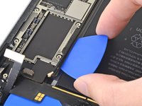
Use the flat end of the spudger to disconnect the display assembly connector from the motherboard socket.
-
-
-
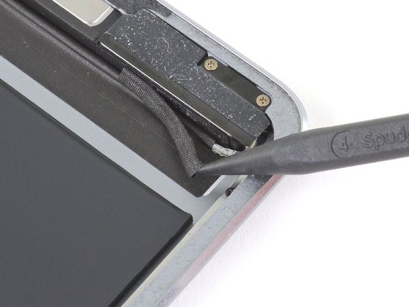
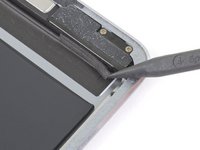
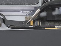
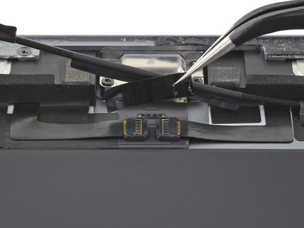
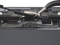
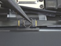
Repeat the previous step for the two remaining connectors.
-
-
-
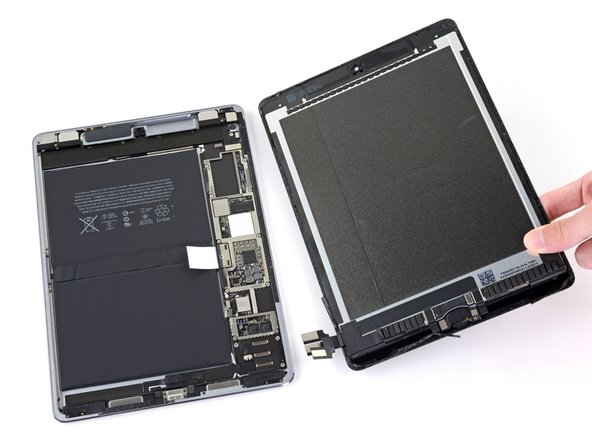
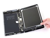
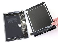
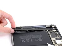
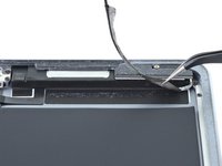
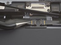
Remove the display assembly from the frame.
You "CAN" skip steps 41 through 98 and 102-109 if you're confident in your repair abilities and PATIENT. Lots of alcohol around all the edges of the battery, and apply heat to the back cover on one half of the battery, the slowly ease your "card under the edges of the battery. Wiggle it back and forth and add more alcohol under the edges of the battery where your working; DONT PUSH your card to hard or you will sli[p and damage components. Then do the same for the other half. When both halves are loose, fold over one end and slide the flat edge off the spudger under the area of the logic board next to the battery connector, then do the same to the other side; you want just enough of a gap under the logic board to lift the battery tab off of the post then you can remove the battery.
ディスプレイアッセンブリを外して、黒くて古い接着テープをはがしすためにぴっぱったら、ディスプレイと本体基盤を接続するコネクターのテーブを不注意で切断してしまった。これで、交換はあきらめで中止。注意されたし。ちなみに、手順41~89は省いてもバッテリー交換ができるのではないかと思います。
If you skip to 99th step, it's very recommended to remove the battery from the opposite side of the logic board. When you arrive at the connector battery-logic board, after warming around the back of the connector, you slightly lift up the logic board so that remove the loop of the battery's connector. It is a good idea to check the shape of the connector in advance.
-
-
-
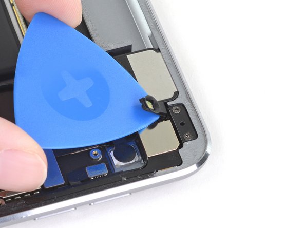
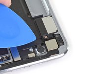
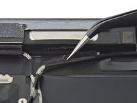
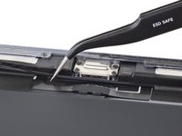
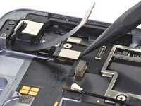
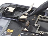
Slide an opening pick under the right ambient light sensor to loosen its adhesive.
The "right ambient light sensor" can be replaced?
If yes, where can I find the replacement part?
The light sensor has a rubber collar. If you lift the cover you can see a tiny peg pushed upwards onto the bottom of the sensor base. It’s the base you need to lift and it is stuck down
-
-
-
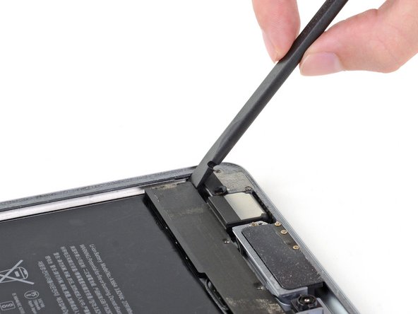
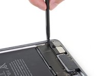
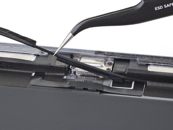
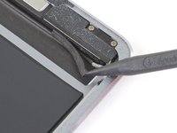
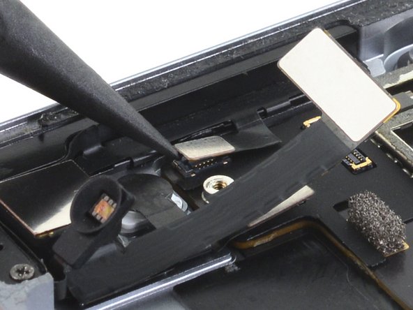
Use a Phillips screwdriver to remove the four 1.9 mm-long screws securing the upper speaker to the frame.
-
-
-
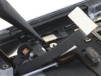
Apply a few drops of high-concentration (90% or higher) isopropyl alcohol under the upper speaker.
-
Wait one minute for the isopropyl alcohol to weaken the adhesive under the upper speaker.
-
-
-
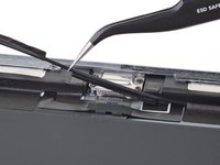
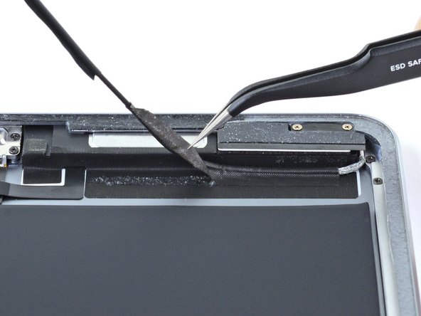
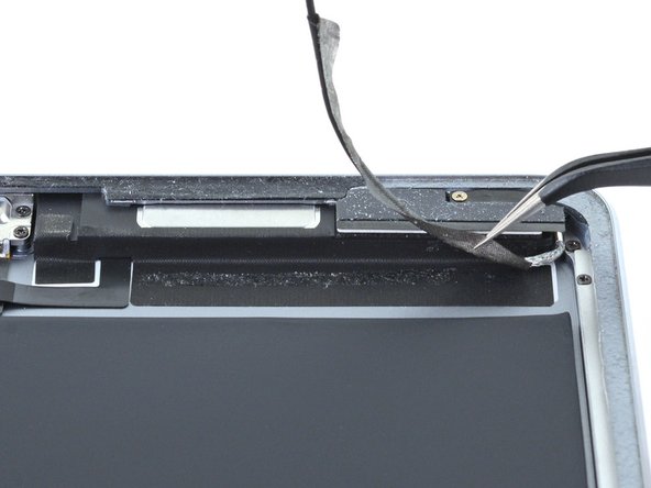
Use an opening tool to pry up the left edge of the upper speaker.
These next 3 steps are the most difficult of the whole process. The speaker is glued down along its whole length which must all be freed. Use the iopener underneath the top of the iPad whilst you are waiting for the alcohol to work to help soften the glue.
On the left hand side, there is a flat cable glued to the back plate and the speaker is then glued on top of the cable. So when you put the alcohol down it’s most likely to deboned the cable which will remain attached to the speaker as you lever it up and need carefully separating somehow.
There is a zif connector on that cable underneath the speaker and just to the left of the front facing camera so there’s not much play. If you are unable to remove cable from the bottom of the speaker, you’ll pull the cable out of the connector as you lift the speaker. Don’t lever the speaker downwards (next step) until this zif connector is detached or you’re trash the connector itself.
There’s also a round wire which passes underneath the speaker, that’s a bit stronger.
-
-
-
Use the flat end of a spudger to push the left side of the upper speaker toward the battery just enough for the left speaker to slide out of its recess in the frame.
The external speaker (headphone socket) on the left side of the speaker must be removed. 2 screws for the cover, 1 for the socket support. As well as a sensor of some sort. The cover for the sensor came off separately.
I didn’t remove that speaker but doing so may give to more access to lift the speaker unit upwards.
DO NOT move the speaker downwards until you have completely separated the speaker from the flat cable glued to the bottom of it on the left hand side or disconnected the zif connector. See my comment in previous step.
-
-
-
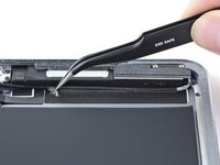
Lift and remove the upper speaker from the frame.
You are going to disconnect the zif connector later. If it’s popped out there’s not need to put it back.
-
-
-
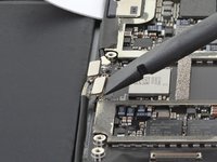
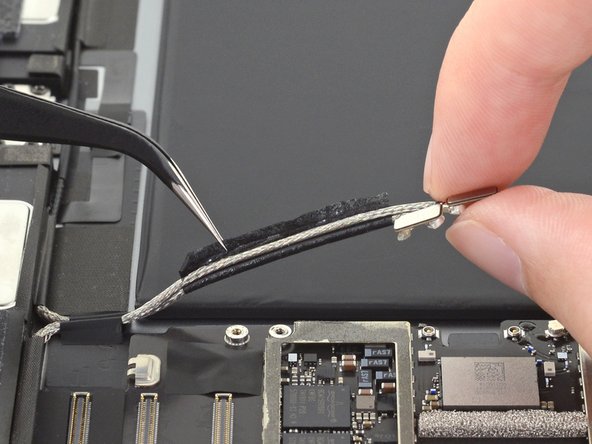
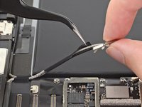
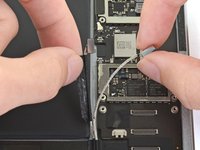
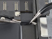
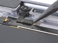
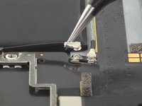
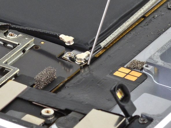
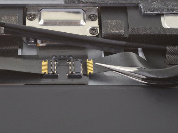
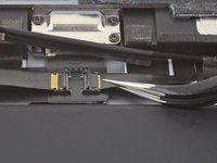
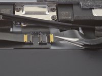
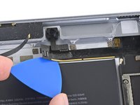
Use the flat end of a spudger to disconnect the right antenna's coaxial connector from its socket.
-
-
-
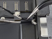
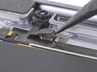
Use the flat end of a spudger to disconnect the left antenna's coaxial connector from its socket.
-
-
-
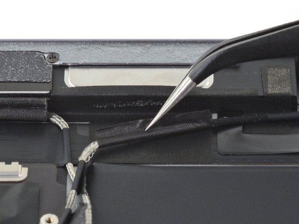
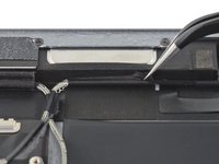
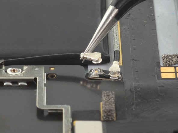
Use the flat end of a spudger to lift the bundled left and right antenna cables away from the frame.
-
-
crwdns2935267:0crwdne2935267:0Tweezers$4.99
-
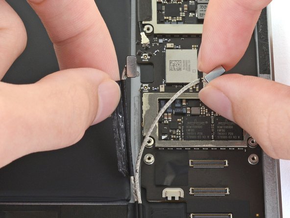
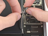
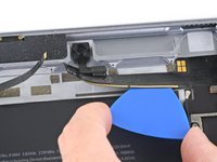
Use a pair of tweezers to remove the adhesive that was securing the bundled antenna cables to the frame.
-
-
-
Use a pair of tweezers to peel up the sticker bundling the left and right antenna cables together.
-
-
-
Peel the right antenna cable off of the sticker.
-
-
crwdns2935267:0crwdne2935267:0Tweezers$4.99
-
Use a pair of tweezers to lift up the small sticker near the lower right speaker securing the right antenna to the frame.
-
-
-
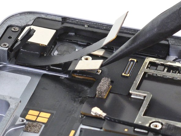
Use the pointed end of a spudger to detach the foam spacer adhered to the second right antenna sticker.
-
-
-
Remove the foam spacer from the second right antenna sticker.
-
-
-
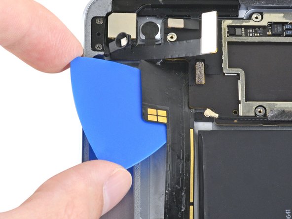
Use a pair of tweezers to detach the large right antenna sticker between the logic board and the antenna.
-
-
crwdns2935267:0crwdne2935267:0Tweezers$4.99
-
Use a pair of tweezers to lift up the small sticker next to the lower right speaker securing the left antenna cable to the frame.
-
-
-
Use a pair of tweezers to detach the large left antenna cable sticker near the lower right speaker.
-
-
-
Use a pair of tweezers to lift the left antenna and its third sticker away from the Lightning port area of the frame.
-
-
-
Use the pointed end of a spudger to detach the foam spacer adhered to the fourth left antenna cable sticker.
-
-
-
Remove the foam spacer from the fourth left antenna cable sticker.
-
-
-
Use a pair of tweezers to lift up the fourth left antenna cable sticker.
-
-
crwdns2935267:0crwdne2935267:0Tweezers$4.99
-
Use a pair of tweezers to remove the sticker covering the left ambient light sensor's ZIF connector.
Der ZIF Stecker liegt versteckt unter der GSM/LTE Antenne.
-
-
-
Use the pointed end of a spudger to flip up the locking flap on the left ambient light sensor's ZIF connector.
-
-
-
Use a pair of tweezers to grip the left ambient light sensor ribbon cable as close as possible to its contacts.
-
Pull the ribbon cable out of the ZIF connector.
-
-
-
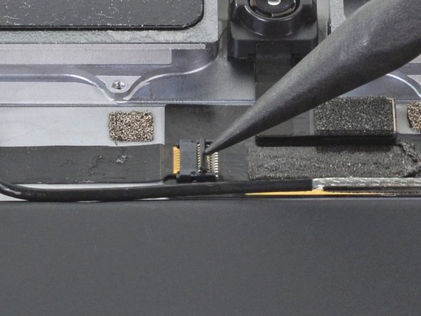
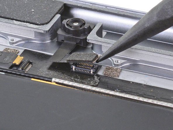
Use the pointed end of a spudger to disconnect the front camera's press connector from its socket.
-
-
-
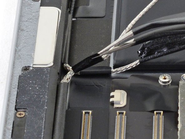
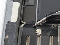
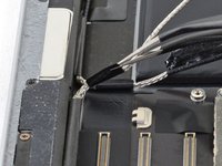
Use a pair of tweezers to grip the bottom coaxial connector on the top interconnect board by its metal frame.
-
Lift straight up to disconnect the coaxial connector from the interconnect board.
I got to this step and the connector separated from the tiny interconnect board. Is there a way to jump these cables without that board?
-
-
-
Apply a few drops of high-concentration (90% or higher) isopropyl alcohol to the edges of the top interconnect board.
-
Wait thirty seconds for the isopropyl alcohol to weaken the adhesive under the top interconnect board.
-
-
-
Use an opening pick to cut through the adhesive under the top interconnect board and detach it from the frame.
-
-
-
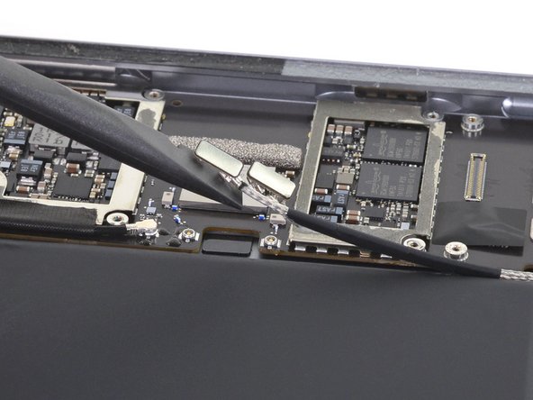
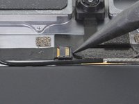
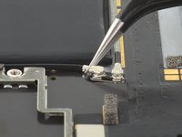
Use the pointed end of a spudger to disconnect the rear camera's press connector from its socket.
-
-
-
Use the pointed end of a spudger to disconnect the power button assembly's press connector from its socket.
-
-
-
Use the pointed end of a spudger to disconnect the volume buttons' press connector from its socket.
-
-
-
Use a pair of tweezers to remove the sticker covering the ZIF connectors near the Lightning port.
-
-
-
Use an opening pick to cut through the adhesive under the right ribbon cable next to the lower speaker (Lightning port oriented up) and detach it from the frame.
-
-
-
Use an opening pick to cut through the adhesive under the left ribbon cable next to the lower speaker and detach it from the frame.
-
-
-
Use the pointed end of a spudger to flip up the hinged locking flap on the left ribbon cable ZIF connector.
-
-
-
Use the pointed end of a spudger to flip up the hinged locking flap on the right ribbon cable ZIF connector.
-
-
-
Use a pair of tweezers to grip the left ribbon cable as close as possible to its contacts and pull the ribbon cable out of the ZIF connector.
-
-
-
Use a pair of tweezers to grip the right ribbon cable as close as possible to its contacts and pull the ribbon cable out of the ZIF connector.
-
-
-
Remove the four Phillips screws securing the Lightning port:
-
Two 2.5 mm screws
-
Two 1.5 mm screws
-
-
-
Strips of adhesive secure the logic board to the frame. In the next steps, you'll weaken and cut through the adhesive to detach the logic board from the frame.
-
-
-
Carefully turn the iPad over.
-
Heat an iOpener and apply it to the top, left, and bottom edges of the rear case for one minute on each edge.
-
-
-
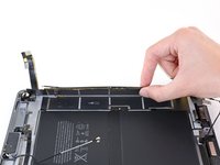
Use an opening pick to cut through the adhesive under the Lightning port ribbon cable to detach it from the frame.
-
-
-
Use a pair of tweezers to lift up the smaller sticker to the left of the Lightning port (when the Lightning port is oriented up).
-
-
-
Use a pair of tweezers to lift up the larger sticker to the left of the Lightning port.
-
-
-
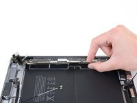
Use a pair of tweezers to grip the Lightning port by the bottom right screw hole.
-
Pull the Lightning port out of its recess.
-
-
-
Apply a few drops of high-concentration isopropyl alcohol under the left edge of the upper logic board arm (Lightning port oriented down).
-
Wait thirty seconds for the isopropyl alcohol to weaken the adhesive under the upper logic board arm.
-
-
-
Use an opening pick to cut through the adhesive under the upper logic board arm and detach it from the frame.
-
-
-
Insert an opening pick about 0.5 inches (13 mm) under the top edge of the larger portion of the upper logic board arm.
-
Leave the opening pick under the upper logic board arm to prevent it from re-adhering to the frame.
-
-
-
Apply a few drops of high-concentration isopropyl alcohol to the right edge of the logic board.
-
-
-
Apply a few drops of high-concentration isopropyl alcohol to the left edge of the logic board.
-
Wait one minute for the isopropyl alcohol to weaken the adhesive under the logic board.
-
-
-
Slide an opening pick about 0.5 inches (13 mm) under the top of the logic board's left side to cut through the adhesive.
-
Remove the opening pick.
-
-
-
Slide the opening pick about 0.5 inches (13 mm) under the logic board's left side next to the battery connector.
-
Remove the opening pick.
-
-
-
Slide the opening pick about 0.5 inches (13 mm) under the logic board on the other side of the battery connector.
-
Remove the opening pick.
-
-
-
Slide the opening pick about 0.5 inches (13 mm) under the bottom of the logic board's left side.
-
Remove the opening pick.
-
-
-
Remove the battery blocker from the logic board.
-
-
-
Remove the opening pick from the upper logic board arm.
-
-
-
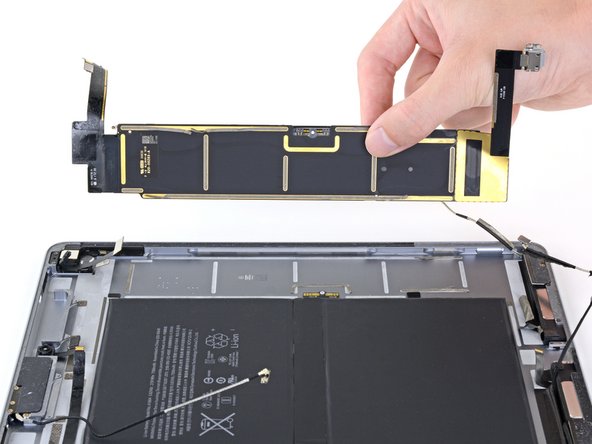
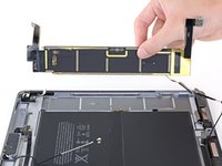
Remove the logic board from the frame.
-


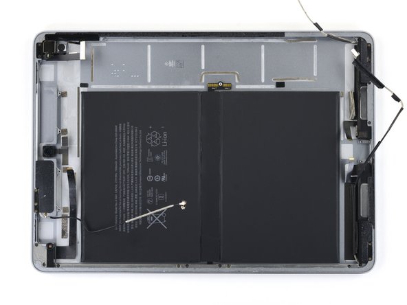


Compare your new replacement part to the original part—you may need to transfer remaining components or remove adhesive backings from the new part before installing.
To reassemble your device, follow these instructions in reverse order.
Take your e-waste to an R2 or e-Stewards certified recycler.
Repair didn’t go as planned? Try some basic troubleshooting, or ask our iPad Pro 9.7" Answers community for help.
crwdns2935221:0crwdne2935221:0
crwdns2935229:05crwdne2935229:0

crwdns2947412:02crwdne2947412:0
where can I buy the logic board for this ?
My iPad Pro 9.7 wifi only has no pinhole for sim card
Michelle - crwdns2934203:0crwdne2934203:0
You’re right! The Wi-Fi only model does not have a pinhole. Skip this step for your iPad.
Arthur Shi -