crwdns2915892:0crwdne2915892:0
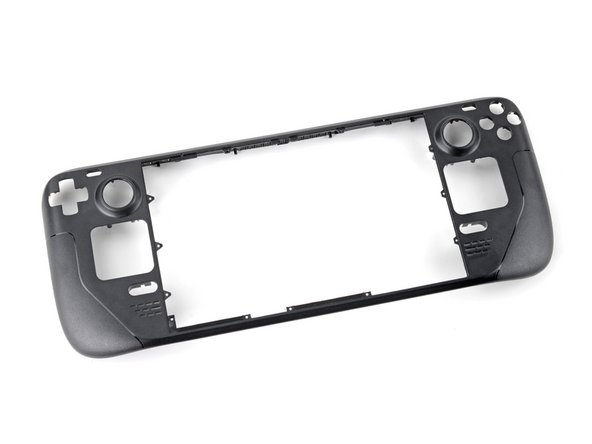
Use this guide to remove or replace the front shell (front cover) on a Steam Deck LCD.
Remember: follow general electrostatic discharge (ESD) safety procedures while repairing your device.
This procedure involves almost a complete disassembly, including removing the display! Know what you're getting yourself into. You'll need replacement adhesives for the display and speakers.
crwdns2942213:0crwdne2942213:0
-
-
Power down your Steam Deck and unplug any cables.
-
-
crwdns2935267:0crwdne2935267:0FixMat$36.95
-
Use a Phillips driver to remove the eight screws securing the back cover:
-
Four coarse thread 9.5 mm-long screws
-
Four fine thread 5.8 mm-long screws
there should be a picture of the SD card slot at the start of every Steam Deck teardown. i know the note is there but i generally use the pictures to guide me and forgetting to remove the SD card is a very critical step
I agree, I just broke mine...
What is the the #1 philips used for? Only the #0 is mentioned in the instructions.
I wish they would specify which size to use for which screws.
Mark D -
I found it easiest to use a PH1 for the red screws, and PH0 for the rest (including the internals.)
Be careful you can strip the screws take your time
I use PH00 bit
I used the PH1 bit for this. You can use smaller bits but ideally there should be no play of the bit in the screw head.
are there playstation replacements (circle,square,cross,triangle)
I used the ifixit tools and used the 00 size for the screws on the back.
I've completed the guide and found it very helpful!
I think somewhere in this part it would be helpful to name the size of the correct Phillips driver to use:
Use a Phillips driver to remove the eight screws securing the back cover:
Four 9.5 mm screws
Four 5.8 mm screws
I used the PH1 for the 9.5mm screws and PH00 for the 5.8mm screws. The PH0 wanted to strip one of the small ones.
FYI - 512gb version has blue threadlocker on the Orange screws.
Just a point for knowledge sake, the Four 5.8mm screws on this step are factory installed with a version of locktite. Not sure why but there will be slight resistance when removing the first time.
Stripped two of the 5.8mm screws, feel pretty dumb, now I'm stuck at step 2 of 43 :|
The screw bit that came with my fix kit just stripped the screws of my steam deck. I guess I should've just sent it in...
Model 1030 SteamDeck uses Torque #6 (CR-V T6) 5.0mm for all 8 screws making it far less likely to damage the screw heads.
Model 1030 is the OLED version, which we have separate guides for! See here: Steam Deck OLED
-
-
-
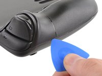
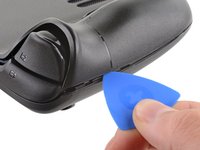
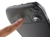
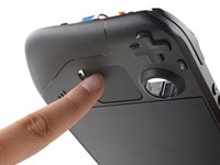
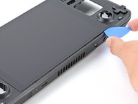
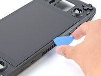
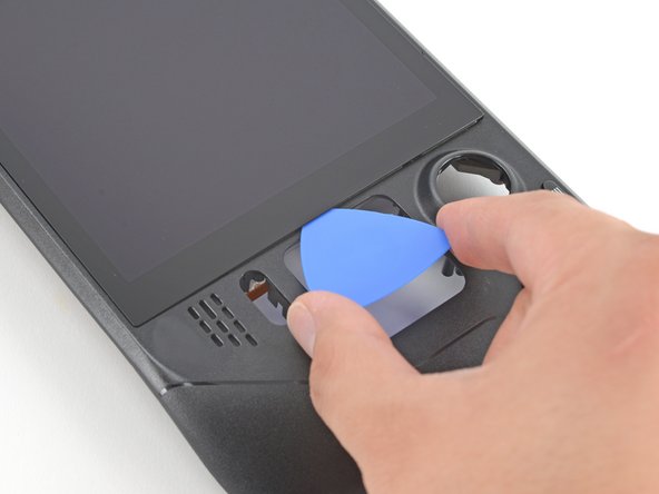
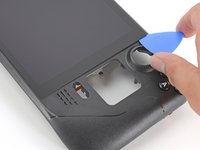
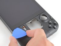
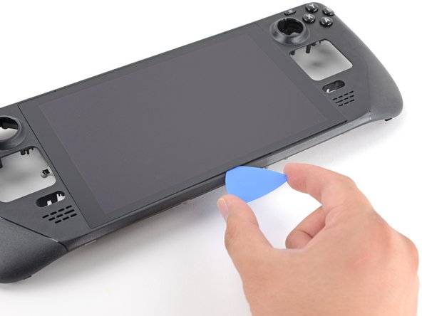
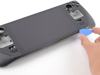
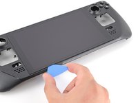
Insert an opening pick into the thin gap between the back cover and the front shell, along the edge of the right grip.
-
Pry up on the back cover to release it from the locking clips.
I found it easiest to start this process at the top of the device near the fan exit.
second that and inserting the pick in the bottom middle and sliding the pick to each side
Sub -
I also found the top near the fan exit to be easier
Thank you for this tip, it definitely was easy starting at the top instead of by the bumper/triggers. After I opened the top I did the bottom and then it was way easier to gently open the sides. be very careful and go slowly to make sure that none of the clips are damaged
Luis B -
this as suggested above:
1. open the top
2. open the bottom
3.gently open the sides
same; i pried from the top of the screen area. I was unable to find an opening on the side
I also started from the middle of the deck and worked my way out since I couldn't get a grip with the pick on the deck's side grips. Since this is a common step for pretty much all guides for opening the deck I think it's also worth noting that you should be careful not to bend the trims/seams where the front and back covers meet with the pick. When I first opened my deck you can definitely see where I nudged the pick in between the covers since I was probably using too much force on the pick itself.
It would be useful to note here that if you want to insert the little blue triangular iFixit opening picks into the right side along the edge, there isn't actually a gap as the directions say, at least not on newer Decks. You'll be making the initial gap using the pick. Brace it on something because you will need to use enough downward force that you're flexing the pick a bit and it'll probably be digging into the skin of a bare hand. With enough force suddenly it will make a click and go in just a bit, and then you're in business.
plastic picks didnt work for me but finger males did the job on prying this open
I found it easiest to open starting with R1 or L1 buttons and proceeding to the center of the top edge
This step was the hardest by far. First I didn't find an opening at the sides, and it did take a really long time until I finally got it open... Then, when I had the one side opening open it didn't just pop out, I needed to slide all the way to the other side with the pick and open everything. I guess they made it even more drop resistant.
-
-
-
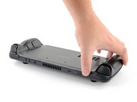
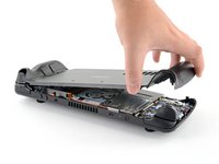
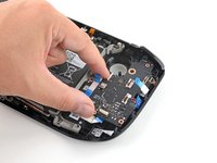
Grip the back cover at the opening you just created and pull it up and away from the device to unclip the long edges.
-
Remove the back cover.
If you have an SD card, you will want to take it out. I followed the guide and didn't think about the SD card I had inside. When I went to snap the case back on it clapped shut on the exposed SD card, shearing it in half and leaving the bottom half stuck in the SD card slot. I am still endeavoring to get it out.
you can use the case that comes with the steam deck to support it once the lid is removed
Luis Barbosa (Armored Saint) - crwdns2934203:0crwdne2934203:0
You can get the pry pick inserted easier if you start in the gap for the shoulder buttons. A lego brick separator works well here
-
-
crwdns2935267:0crwdne2935267:0Tweezers$4.99
-
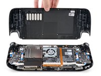
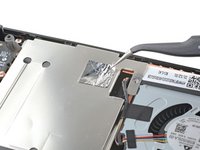
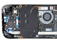
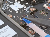
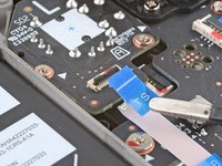
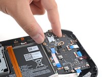
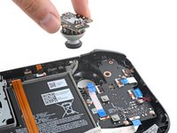
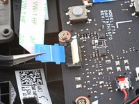
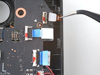
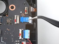
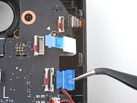
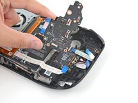
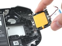
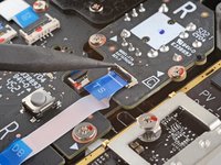
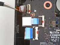
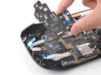
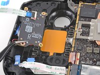
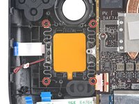
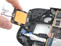
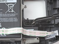
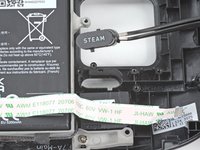
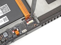
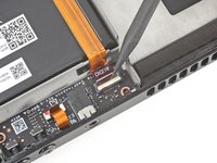
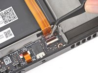
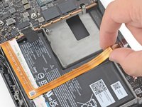
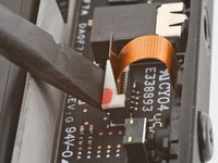
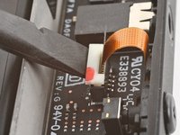
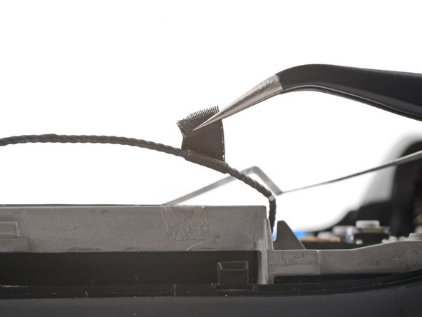
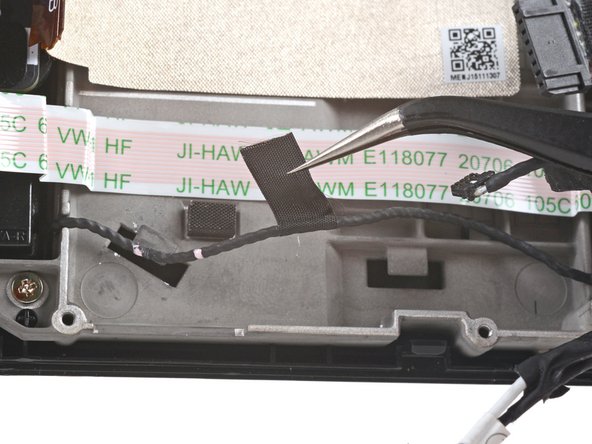
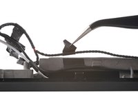
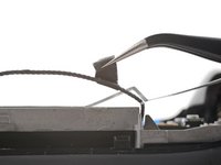
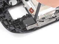
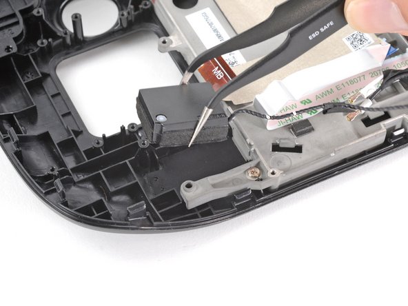
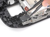
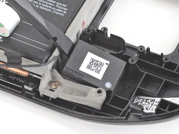
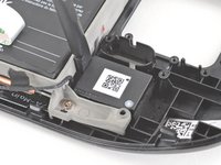
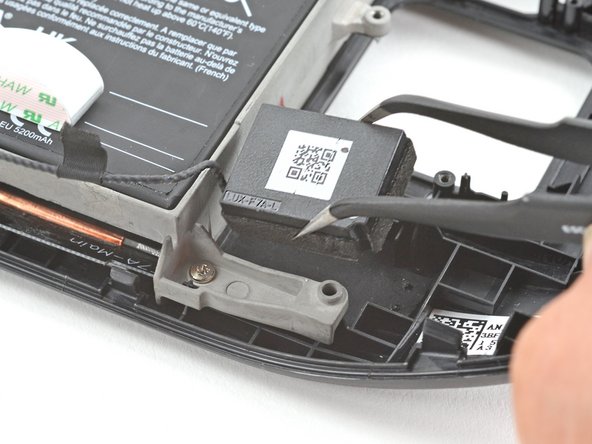
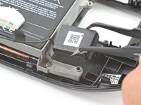
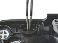
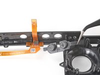
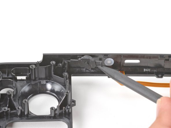
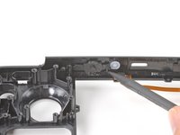
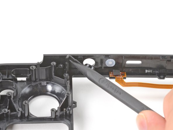
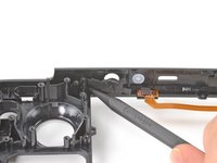
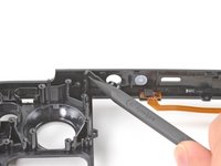
Use a pair of tweezers to remove the piece of foil tape covering the hidden screw on the board shield.
Use some heat here from a hairdryer to make this part easier.
If you screw up here you can replace the little aluminium square with some aluminium tape from Amazon. No less than 50 microns thick, slightly thicker is fine. and the square is 13mm both ways.
Thanks for that Matt, i destroyed the original tape and i had no solution since i read your comment.
there are other new version of board shield from 2023.
Is it alright to use the deck without the tape?
You should not. This is EM shielding to protect your processor and ram from radio waves in the air
I found out my 3 Weeks new Steam Deck is a old Version... gg. Valve...
wenn ich aluminium foile benutze, womit soll ich sie dann verkleben?
If we have the new version with the black shield, how do we access the SSD?
I need this part, does anyone know where to get it?
PSA: The only purpose of steps 5–8 is to enable you to disconnect the battery, which is not essential. I skipped steps 5–8 and did not have any trouble with the repair.
-
-
-
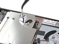
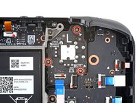
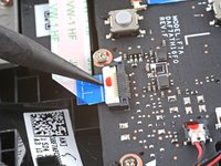
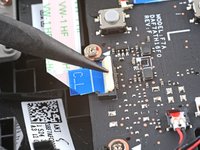
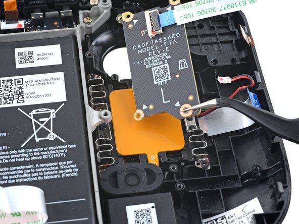
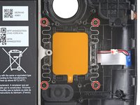
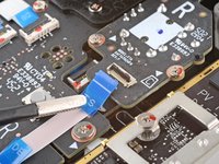
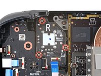
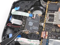
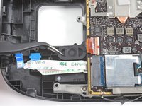
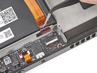
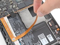
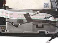
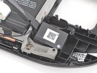
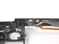
Use a Phillips driver to remove the three screws securing the board shield:
-
One 3.4 mm screw
-
Two 3.7 mm screws
The procedure ended here for me, used an ifixit PH 00 bit on the screw behind the aluminium tape, bit wouldnt bite too great, one wrong twist and the screw was stripped. Not sure who or what initially screwed in that particular screw as the rest of the screws on the shield were fine, but boy is it in there tight. So now i have a stripped screw and a botched ssd replacement, don't think valve will let me RMA for this, but i'll give it a try and update accordingly.
Any updates? Did they let you RMA?
I found one screw to be ridiculously tight too, managed to undo it without stripping thanks to reading your comment beforehand and going extra careful. Not going to lie, it was a tense moment :D
Andy HL -
I'm stuck in the same place. I haven't fully stripped it, but I can tell you that if I try and make it budge it will strip. The thing is massively overtightened. The driver fit fine, the metal just gives way before the screw will budge.
I think the tendency is to go too small on the screwdriver bits because you're working on small electronics.
I used the PH1 bit on the screw under the foil and the PH0 bit for the two remaining screws without any problems.
What does this shield actually do? Some kind of magnetic protection?
if I had to replace the key (R2) and that's it, can I directly remove it or do I have to act here on the motherboard too?
have you gotten an answer yet? trying to change mines as well but dont wanna do too much to the deck
briaNN -
button Not key, i’m sorry
I used the ifixit tools and used the 00 PH for these screws with no issue
If only swapping the SSD, it is not necessary to remove the top left 3.7mm screw. The heat shield is flexible enough that you can move it out of the way to access the SSD screw. For me this was necessary as the 3.7mm screw was completely unmovable and quickly stripped.
FYI there is a little pin on the cover that slots into the board. It is located near the top screw. I needed that to be inserted for the cover to go back down properly.
For anyone who may have stripped a 3.7mm screw, Steam Support states it's M1.6 diameter with a 0.35 thread pitch and a 3mm length. Hopefully that'll help anyone trying to locate a replacement screw. Hoping iFixIt can make an internal screws kit as they're kinda hard to find the right one online.
Did valve change the shield recently as my new 64gb deck has a black shield with no hidden screw.
Yes there's a new hardware revision out there that some people are getting. Consider stopping at this point and putting your deck back together if you have one of these new hardware revisions (the fan is quite different as well to the pictures) until iFixit has an updated repair guide.
Simon M. -
There are only 2 screws now, but be careful taking the shield off, because there are still thermal pads under it sticking it to a heat pipe.
Are they m2 3.7mm screws? I am looking to replace mine because they instantly stripped and I had to remove them with needle nose pliers because they were over tightened.
I need this piece, can someone help me where can I find it please?
Hi, is it possible to buy these shields somewhere? I am extremely interested in buying a replacement.
The refreshed model 1030 has 2 T6 torx screws instead of Philips
Model 1030 is the OLED version, which we have separate guides for! See here: Steam Deck OLED
-
-
-
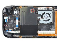
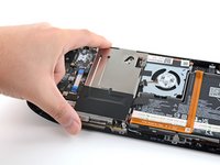
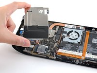
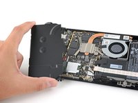
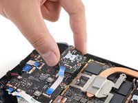
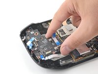
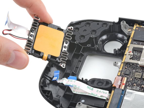
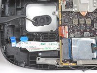
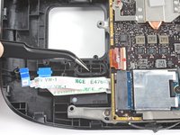
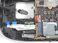
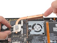
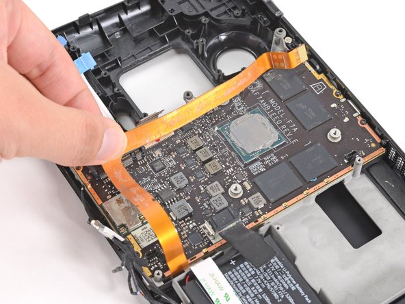
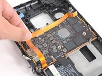
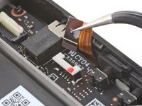
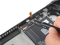
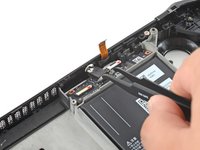
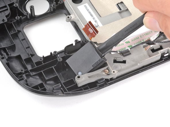
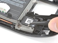
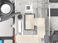
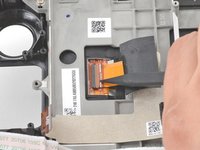
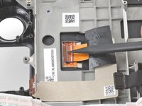
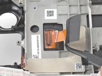
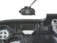
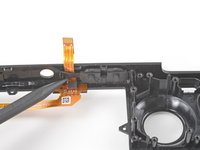
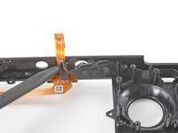
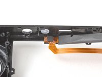
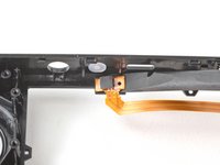
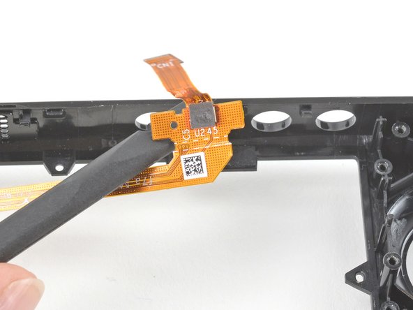
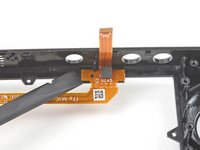
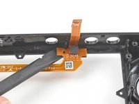
Remove the board shield.
When putting back on, run a pick along the edge of the shield between the wires to make sure nothing is pinching and the wires are clear of the shield before screwing down.
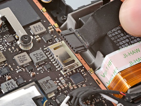
During reassembly, ensure that the fan cable lays on the side of the board shield and isn't pinched underneath.
Are you saying that the fan cable should be positioned above the board shield instead of being pressed down by it? Just like the image shows, where it 'lays on the side of the board shield'?
Necesito esta pieza la mía no la traía se ve que se la quitaro
-
-
-
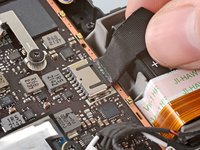
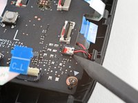
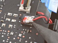
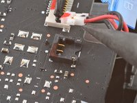
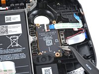
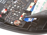
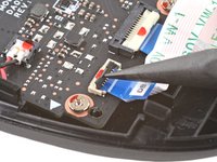
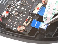
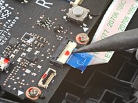
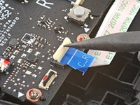
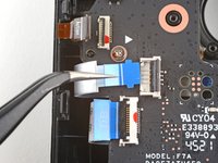
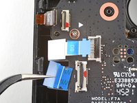
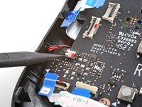
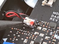
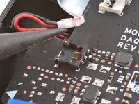
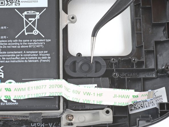
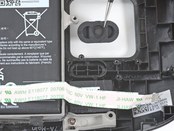
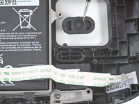
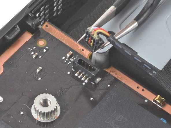
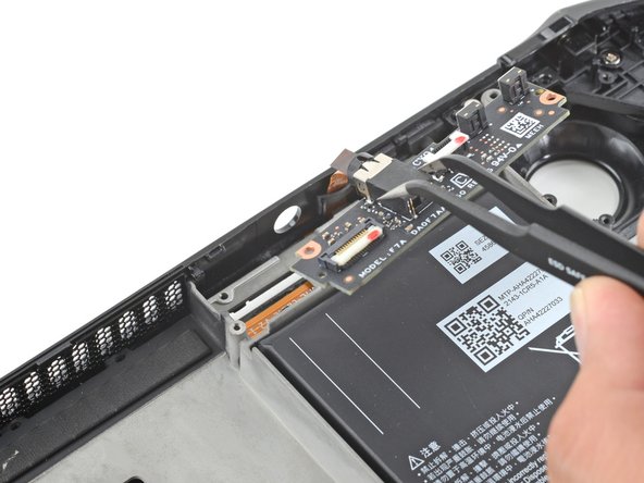
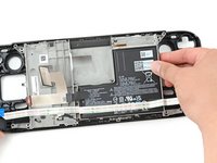
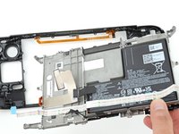
Grip the battery cable by its pull tab and pull it directly away from the motherboard to disconnect it.
After fully reassembling my device I found that my battery was not showing any stats anymore. I couldn't start the device without being plugged in, however if I restarted it would stay on even if my power cable was detached. Battery showed 0%. It turns out I had not fully reinserted the battery cable at this stage during reassembly. MAKE SURE YOU PUSH IT ALL THE WAY BACK IN!
Awesome thanks for this tip!
It is helpful to lift up gently with a the tapered end of a spudger underneath the tucked-in portion of the battery cable, creating a bit of flex in the cable before pulling on the pull tab. I found that without doing so, the fabric pull-tab simply tore off of the cable under light-to-moderate force (the fabric itself ripped cleanly across, like a paper towel). Careful, gentle pressure with a spudger can be used to remove the plug by prying gently on the rear ridge of the plastic plug (not the wire!) if this happens.
This is exactly what happened to me. Maybe it was a pull tab previously, mine was a ribbon cable that tore - captured the image here: https://www.ianwootten.co.uk/2022/11/22/...
This was the best approach (and I feel safest for the wiring) for me. Mostly push pressure on the plastic ridge with some minor pull tension on the fabric.
Victor -
I found it less scary and easier to remove the battery connection by using a fingernail on the ridge and pushing it off the connector. I felt like pulling on the battery cable was too harsh.
Yeah, pulling cables like these is usually ill advice. They might be fine if it's a new device, but for old devices that have been sitting there for years, there's a good chance the connector has grown brittle and the cable might just come off separately (something I learnt the hard way).
skzm -
I second this approach. For me, the cable felt way to flimsy and the connector wouldn't budge even under moderate force. Except I used the flat end of a spudger to "scrape" it out.
Misza -
Upon plugging the battery back in, I found it easy to use two spudgers- one on each side- to pull/push the connector back into it's port. Be careful to not put any pressure on the battery wires themselves.
When reconnecting the battery cable, you'll know when it's inserted and power is restored, because the white LED will illuminate at the top of the Deck near the power button. You should be able to see it while you're reconnecting the battery cable
This is only true if you haven't put the deck into battery storage mode as directed.
Why not just let the battery discharge completely and then not have to disconnect it?
Completely discharging a battery reduces its lifespan. It's completely unnecessary.
Because no lipo battery is ever completely discharged -- you would not be able to recharge it if it was. There will always be enough power left in it to cause damage if shorted even if it isn't charged enough to power up the device it's connected to.
I would personally not recommend pulling the tab. It doesn’t apply force at the correct angle. You should revise these instructions to advise using a combination of pulling on the tab, and careful pressure on the connector towards the right of the mainboard to carefully work it out.
Using the pull tab alone could cause problems if not done extremely carefully.
This part was wayyyyy easier than I anticipated and I worried for nothing because I used the ifixit spudger to push it out a bit and then I literally used my finger nail and was able to slide it right off. Dont be afraid, its not that difficult and its not that delicate to break if you do it patiently
I inserted the cable very firmly with a spunger, being careful not to press down too hard on the cables, and even tried redoing it, but I don't see any LED illumination. I am now unable to boot the deck into the boot manager. Any additional tips?
What is the risk of not unplugging the battery? Just curious!
Once I was changing termal paste on my Windows based expensive tablet PC... And I was so scared to disconnect any cables (there was many of them), so I did it all with battery connected (I didn't even knew where is battery cable). When I tried to put board shield back... it didn't go right into needed place... and short circuit some small component. It flashed. That was the end of my repair. Dudies from repair service later told me that multiple components fried including CPU, so repairing is too hard. That's what can happen if you don't disconnect battery.
To pull the battery out I used my spunger, but the batter had actually not space to be pulled out completely. I needed to lift the cable up with the spunger to get the cable fully out. When plugging it in again I had to press the battery down kinda hard so it would fit again. This was really scary and I recommand using two spunger as someone said above.
Does it have to be a clean fingernail?
I disagree with the order here: I think the battery should be disconnected right after step 4. You can do that before touching anything else by gently pulling the pull tab to the right.
If all you want to do is to disconnect and reconnect your battery (because your Steam Deck is not booting up... again...) then with a bit of finesse, luck and a flat plastic tool you can even push it back in without removing the shield. Make sure it went all the way back in.
Be very careful with this tab, it rips easily!
-
-
-
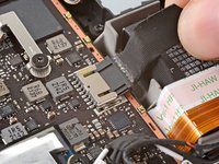
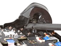
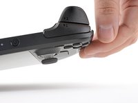
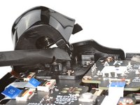
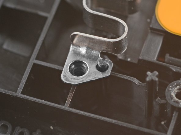
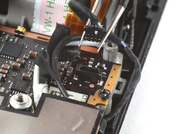
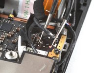
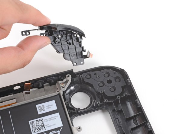
Place the flat end of a spudger onto the inside edge of the trigger's left clip.
-
Pivot the trigger clip out, away, and up from the peg to unlatch it.
This step is taking me a while to get the trigger out.
I solved this by pushing the trigger to the left while inserting the spudger.
Twist the spudger, it will take some force.
The trigger and spring will fly out.
Tom Sid -
Yeah, the trigger takes a bit and is a little tricky to get out. Eventually got it though
Kane -
-
-
-
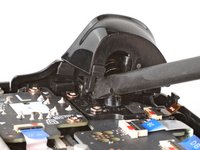
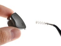
Remove the left trigger.
In case the spring gets lost, it's 19 mm long with about 14 coils.
Omg thank you
-
-
-
Use a Phillips driver to remove the three 5.2 mm screws securing the left trigger bracket.
-
-
-
Remove the left trigger bracket.
If I only need to get to this part to check if I have to change the button or the daughterboard, do I HAVE to disconnect the battery ? The less I fiddle with things the more likely it is that I won’t break anything else…
-
-
crwdns2935267:0crwdne2935267:0Tweezers$4.99
-
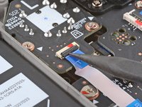
Use the pointed end of a spudger to lift up the small locking flap on the thumbstick cable's ZIF connector.
-
Use a pair of tweezers to slide the cable out of its connector.
My tweezers keep slipping off, this pull tab has poor grip.
I ended up just using my fingernails and it worked.
Tom Sid -
-
-
-
Use a Phillips driver to remove the three 5.2 mm screws securing the thumbstick.
-
-
-
Remove the left thumbstick.
-
-
-
Use the pointed end of a spudger to lift up the small locking flap on the button board interconnect cable's ZIF connector.
-
Use a pair of tweezers to slide the cable out of its connector.
Interconnect cable is along bottom of left board (on your right hand side). Ought to put a picture of where it is for easier reference.
-
-
-
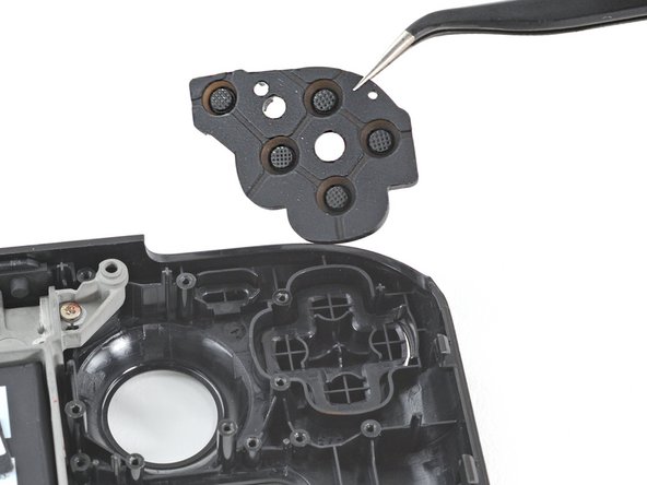
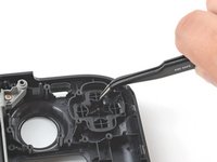
If any connectors are covered with tape, use a pair of tweezers to remove it.
-
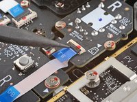
Use the pointed end of a spudger to lift up the small locking flaps on the rest of the button board ZIF connectors. Use a pair of tweezers to slide the cables out of their connectors:
-
Disconnect the D-pad cable.
-
Disconnect the touchpad board cable.
-
Disconnect the touchpad cable.
-
-
-
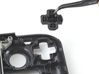
Use the pointed end of a spudger to lift up on the haptics cable to disconnect it.
Any advice on resoldering a disconnected haptics connector housing?
If you dont accidently launch the housing some where you cant find it
Jimbo -
Der Stecker steckte fester im Gehäuse als das Gehäuse auf der Platine... Eine Idee, wie das in Ordnung gebracht werden kann?
Broke the housing in half, still usable though. This was while only prying the connector, which stretched the housing too much. I highly recommend the flipping over the edge alternative :)
-
-
-
Use a Phillips driver to disconnect the four screws securing the left button board:
-
Three 5.2 mm screws
-
One 3.9 mm screw
during reassembly you will need to remember to line up board with 2 plastic mounts. pcb has good flex and can push down top to get top screw to line up flush
also the 2nd cable from the top (the one below shoulder button cable) should be pulled free before tightening your screws lol
-
-
-
Remove the left button board.
This is useful, but how do I get a Left Button Board? Mine is damaged in the left bumper button micro switch and I need a replacement.
i thought i needed to replace L1 but i need to replace daughter board too. Valve has said they will supply left daughter boards they are just sold out rn
B P -
Same, i replaced the assembly for nothing, its the board that needs to be replaced, since i cant solder at all and its the blue button that is faulty
Where can I purchase a board
I need this board to fix my deck
que precio tiene esta pieza, se daño la de mi steam deck
when will the button board be for sale?
L4 button not worked. When will the button board be for sale?
Will a button board be available for purchase soon?
Please provide daughter board, l1 button stopped working. Pads lifted off the board.
Please sell a button board. L1 button stopped working. Seems to be a common issue.
Will a button board be available for purchase soon?
Also need a button board....
Guys, I have the same problem as everyone else. The STEAM button stopped working almost immediately after purchase, Steam actually refused the warranty - they offered me to bring the console myself to the other side of the world, although they could have simply sent a replacement part or a new one. You can’t buy spare parts anywhere - they simply weren’t made “in reserve.” As a result, I have a dead, useless console for a lot of money. No trust in Valve now. I'm thinking of filing a class action lawsuit against the company. Maybe we can get together? I'm @paaladin on social networks and Steam.Where can I buy this board? If this board isn't available, what else could I do to fix the L1 button switch?
Same issue happened to me soon after purchasing Street Fighter 6. Once you continue pressing these triggers excessively, they eventually bend down where as the trigger can't activate the Micro Switch any more. Luckily I purchased my Deck New, directly from Valve and not used. So in my case they had no shipping me a New unit immediately after receiving my faulty Deck. So what I did to remedy this issue was purchase a Victrix Pro FS Arcade stick just to play my favorite fighting game Street Fighter 6 on the deck and PC. These triggers definitely don't hold up to constant presses + pressure. I do feel bad for those that find themselves in this situation but purchase there deck used with no form of warranty.
-
-
-
Use a Phillips driver to remove the four 4.7 mm screws securing the touchpad board.
-
-
-
Remove the touchpad board.
-
-
-
Use a Phillips driver to remove the four 4.7 mm screws securing the touchpad.
-
-
-
From the front of the Steam Deck, use your finger to push the left touchpad partway through the front shell to unseat it.
-
Lift the touchpad out from underneath the overhanging section of the midframe.
-
Remove the touchpad.
-
-
-
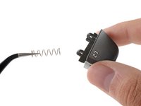
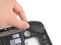
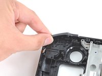
Place the flat end of a spudger onto the inside edge of the trigger's right clip.
-
Pivot the trigger clip out, away, and up from the peg to unlatch it.
This is unnecessary on the revised Model 1030 if you only need to access the Quick Access button. Jump to Step 13.
Model 1030 is the OLED version, which we have separate guides for! See here: Steam Deck OLED
-
-
-
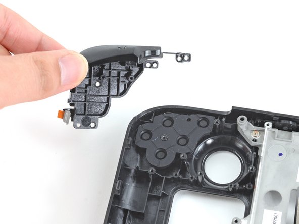
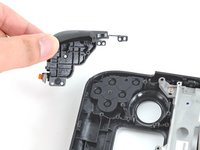
Remove the right trigger.
This is by far the hardest part of the entire assembly. I don't know if its because I dropped mine but the trigger takes an incredible amount of force to get off, don't be afraid to break it. I still have no idea how to put the trigger back on, it just wont budge.
In case the spring gets lost, it's 19 mm long with about 14 coils.
Thank you this is helpful
reconbot -
When putting this back on be sure to note the instructions for reassembly above. Catch the outer peg, align the inner one, and push. Having a flashlight on the inner peg helped me get it lined up.
-
-
-
Use a Phillips driver to remove the three 5.2 mm screws securing the right trigger bracket.
-
-
-
Remove the right trigger bracket.
The right bumper button on my switch deck stopped working after the deck was accidentally dropped from 5ft. When I got to this step of the instructions, I was able to see that the momentary switch that the button triggers had been bent backwards from the impact, making it difficult for the button to trigger the switch. I bent the switch back to its original position, which fixed the mechanical problem. Unfortunately the solder joints for the switch cracked when I pressed the switch forward. I re-flowed the solder joints with a tiny Weber iron that I filed down to a narrow point. The button works properly now.
-
-
crwdns2935267:0crwdne2935267:0Tweezers$4.99
-
Use the pointed end of a spudger to lift up the small locking flap on the thumbstick cable's ZIF connector.
-
Use a pair of tweezers to slide the cable out of its connector.
-
-
-
Use a Phillips driver to remove the three 5.2 mm screws securing the thumbstick.
This is unnecessary if you only need to access the Quick Access button on the revised Model 1030. Jump to step 16.
Model 1030 is the OLED version, which we have separate guides for! See here: Steam Deck OLED
-
-
-
Remove the right thumbstick.
-
-
-
Use the pointed end of a spudger to lift up the small locking flap on the button board cable's ZIF connector.
-
Use a pair of tweezers to slide the cable out of its connector.
On the revised Model 1030 it is all black and you will need to raise the ribbon slightly to remove it. Don’t just try to pull it backwards as there is a notched retainer.
-
-
-
Use the pointed end of a spudger to lift up the small locking flap on the button board interconnect cable's ZIF connector.
-
Use a pair of tweezers to slide the cable out of its connector.
Be very mindful of this cable during re-assembly, if this cable isn't fully seated properly the deck will turn on slowly and not be able to recognize any inputs besides the touch screen.
Hmm, I wonder if this is my problem. I replaced my case with the Clear JSAUX one. Everything went fairly well, until I closed it up and noticed none of my buttons worked anymore. By "seated properly", how do you tell? When I look at it, it looks the same as the picture, with the white line showing
Eric, flip up the white locking flap and remove the cable. Then reinsert the cable — it should go in smoothly with no resistance, hence its name (ZIF = "Zero Insertion Force") — if you feel resistance, there might be something blocking the cable or its connection. If it slides in smoothly, make sure it bottoms out evenly and isn't at an odd angle. If everything looks good, your problem is probably elsewhere.
-
-
-
If any connectors are covered with tape, use a pair of tweezers to remove it.
-
Use the pointed end of a spudger to lift up the small locking flaps on the rest of the button board ZIF connectors. Use a pair of tweezers to slide the cables out of their connectors:
-
Disconnect the action buttons cable.
-
Disconnect the touchpad board cable.
-
Disconnect the touchpad cable.
Be especially careful disconnecting and reconnecting the touchpad cable. It is short and can pull out on the touchpad side fairly easily. Reconnecting it requires splitting open the touchpad itself which is difficult to do without damaging the springs.
-
-
-
Use the pointed end of a spudger to lift up on the haptics cable to disconnect it.
Personally, i think this should just be a suggested step, since the connector is different and requires more force to disconnect than the ribbon cable connectors and you can leave this connected and lay the board over to the side without disconnecting this and still access the buttons.
I agree with Peter on this. I tried fixing my right bumper before ordering a replacement and during disassembly I followed these instructions exactly and still broke the bracket that holds the haptics connector. Luckily my haptics seem to still be working after putting it back together but I have a feeling it will disconnect on its own after some time and I will be needing a whole new button board.
I did this very carefully and the bracket still broke
I broke the down part of the bracket as well. Glued it back on with some crazy glue applied with a wooden toothpick (to make sure to not touch anything else). Haptics still working. Next time I don't think I'll remove that connector.
Leave the haptic connector on and just move the button board out of the way. You will likely brake the haptic connector bracket by trying to remove it.
I agree with everyone above. Attempting to disconnect the haptics is not worth it as it breaks extremely easily
Please remove this step. It is virtually impossible to remove this without breaking the housing and it's ultimately not necessary.
Wish I had seen this beforehand. My right connector just broke off. Ughhh.
This also screwed up my haptics as it basically fell apart as soon as it was touched
Can this just be soldered back on or do I need a new button board? Because I have looked online and they seem impossible to find.
-
-
-
-
Use a Phillips driver to disconnect the four screws securing the right button board:
-
Three 5.2 mm screws
-
One 3.9 mm screw
Once again, for the revised Model 1030, all of these screws are T6 of varying sizes, nothing like the original. Use your favourite way of keeping track of where to return the screws in their correct holes.
Model 1030 is the OLED version, which we have separate guides for! See here: Steam Deck OLED
-
-
-
Remove the right button board.
-
-
-
Use a Phillips driver to remove the four 4.7 mm screws securing the touchpad board.
-
-
-
Remove the touchpad board.
-
-
-
Use a Phillips driver to remove the four 4.7 mm screws securing the touchpad.
-
-
-
From the front of the Steam Deck, use your finger to push the right touchpad partway through the front shell to unseat it.
-
Lift the touchpad out from underneath the overhanging section of the midframe.
-
Remove the touchpad.
-
-
crwdns2935267:0crwdne2935267:0Tweezers$4.99
-
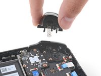
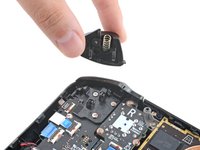
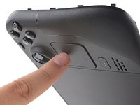
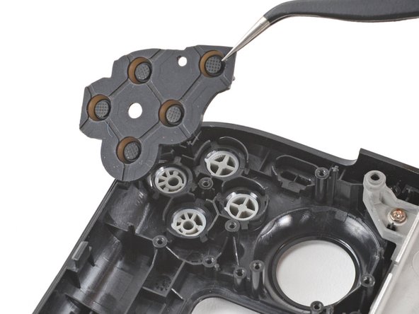
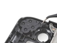
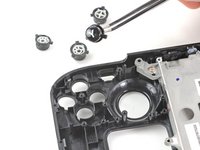
Use a pair of tweezers to remove the quick access button membrane.
-
-
-
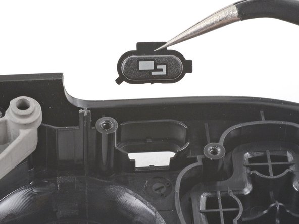
Use a pair of tweezers to remove the quick access button.
-
-
-
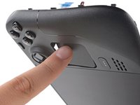
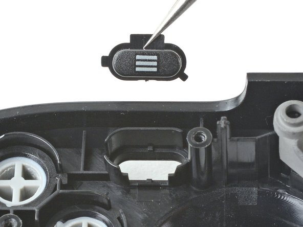
Use a pair of tweezers to remove the Steam button membrane.
-
-
-
Use a pair of tweezers to remove the Steam button.
-
-
-
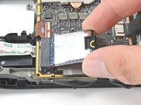
Use a Phillips driver to remove the 3.4 mm screw securing the SSD.
-
-
-
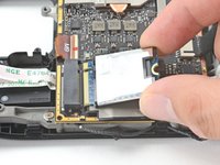
Grip the end of the SSD and pull it away from its M.2 board connector to remove it.
-
-
-
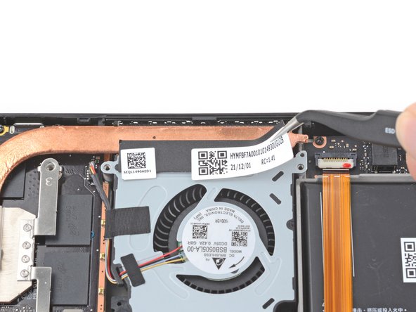
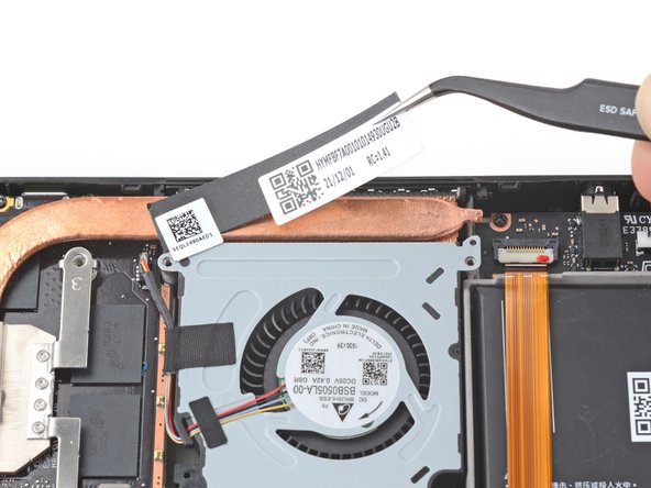
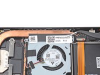
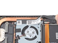
Use a pair of tweezers to remove the sticker from the top edge of the fan.
If you feel comfortable completing step 51 (disconnecting the fan) with the heat sink in place, this step can be skipped. You can then remove the heat sink and the fan as a unit, leaving the sticker intact.
-
-
-
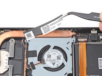
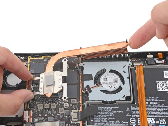
Use a Phillips driver to loosen and remove the two screws securing the heatsink to the motherboard:
-
One captive 3.5 mm screw
-
One 3.4 mm screw
-
-
-
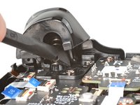
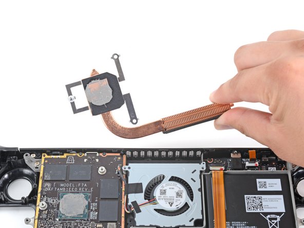
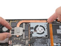
Lift and remove the heatsink.
-
-
-
Use a pair of tweezers to grip the edges of the fan connector and pull up to disconnect it from the motherboard.
-
-
-
Use a Phillips driver to remove the two 3.7 mm screws securing the fan.
-
-
-
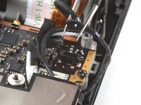
Use a pair of tweezers to grip the edges of the speaker connector and pull up to disconnect it from the motherboard.
-
-
-
Use a pair of tweezers to peel up and remove the Wi-Fi shield tape.
-
-
-
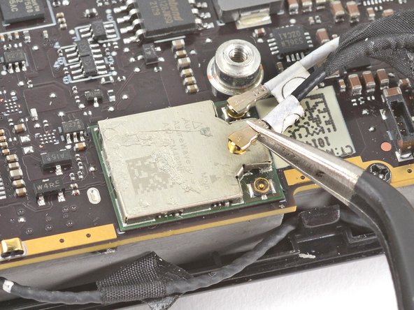
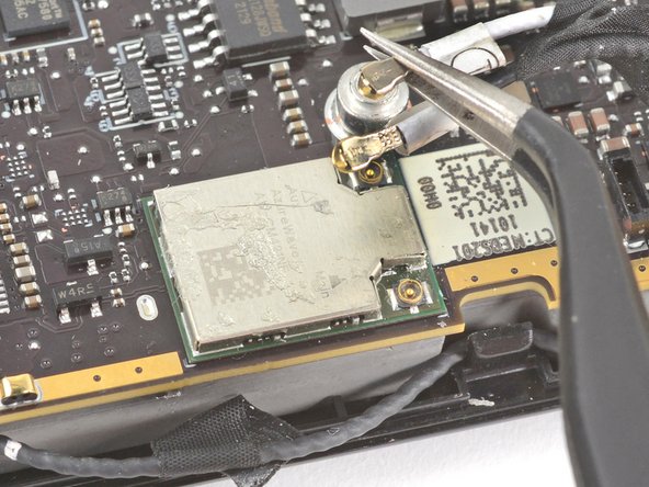
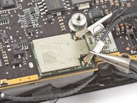
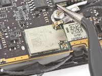
Use a pair of tweezers to grip the antenna connector close to its base.
-
Pull straight up to disconnect the cable.
-
Repeat for the second antenna cable.
-
-
-
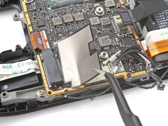
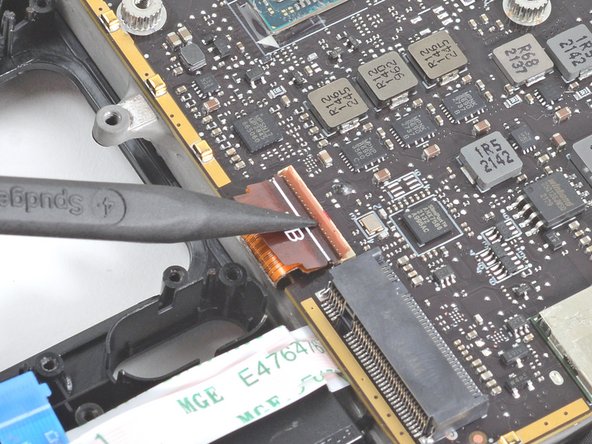
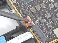
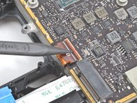
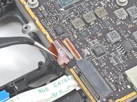
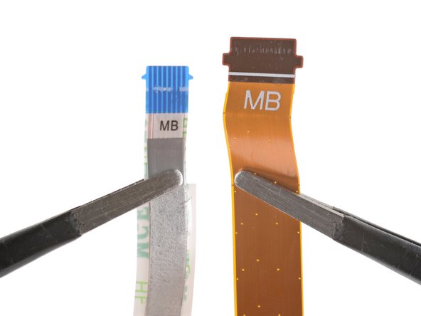
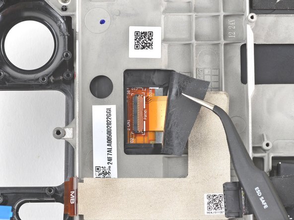
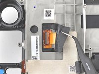
Use the pointed end of a spudger to lift up the small locking flap on the display cable's ZIF connector.
-
Use a pair of tweezers to slide the cable out of its connector.
-
-
-
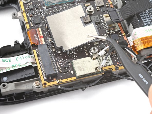
Use the pointed end of a spudger to lift up the small locking flap on the audio cable's ZIF connector.
-
-
-
Use a pair of tweezers to slide the cable out of its connector.
-
-
-
Carefully peel the audio cable off of the battery.
-
If the adhesive is stubborn, don't force the cable. Lightly heat the audio cable using an iOpener or a hair dryer to soften the adhesive.
-
-
-
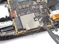
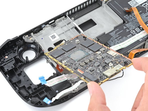
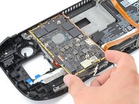
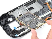
Use a Phillips driver to remove the three 3.7 mm screws securing the motherboard.
-
-
-
Remove the motherboard.
-
-
-
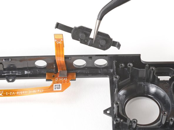
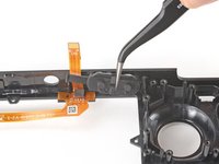
Use the pointed end of a spudger to lift up on the mic cable's white locking tab.
-
Use a pair of tweezers to pull the mic cable up and out of its connector.
-
-
-
Use a Phillips driver to remove the two 3.7 mm screws securing the audio board.
-
-
-
Use a pair of tweezers to grip the audio board by the headphone jack.
-
Pivot the board up and out of its recess to remove it.
-
-
-
Use a pair of tweezers to peel up the tape bundling the speaker wire to the Wi-Fi antenna cables.
-
-
-
Use a pair of tweezers to peel up the various strips of black tape routing the speaker wire along the bottom edge of the chassis.
-
-
-
Insert the flat end of a spudger between the right speaker and the frame.
-
Pivot the spudger up to separate the speaker from the light adhesive securing it against the front shell.
-
-
-
Use a pair of tweezers to grip and remove the right speaker from its cavity.
-
-
-
Insert the flat end of a spudger between the left speaker and the frame.
-
Pivot the spudger up to separate the speaker from the light adhesive securing it against the front shell.
-
-
-
Use a pair of tweezers to grip and remove the left speaker from its cavity.
-
-
-
Remove the tethered right and left speakers.
-
-
-
Use a pair of tweezers to peel back the sticker covering the display connector.
-
-
-
Use the pointed end of a spudger to lift up the small locking flap on the display cable's ZIF connector.
-
Use a pair of tweezers to slide the cable out of its connector.
-
-
-
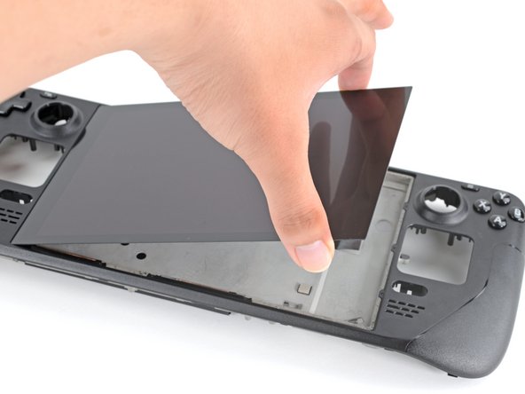
Prepare an iOpener and apply it to the top edge of the display for one minute.
-
-
-
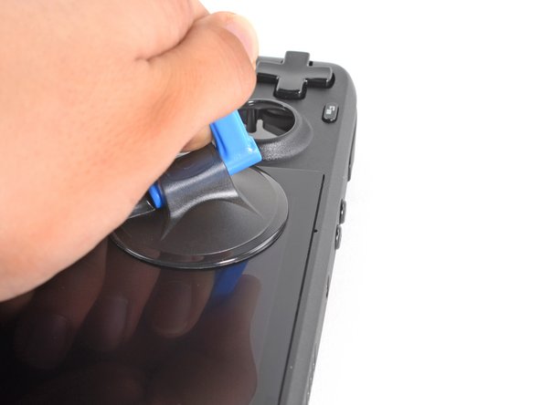
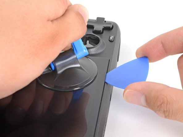
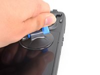
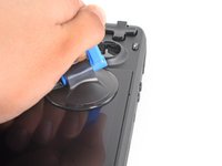
Apply a suction cup to the top left corner of the display by pressing down on it to create suction, as close to the edge as possible.
-
Pull up on the suction cup with strong, steady force to create a gap between the display and the frame.
-
Insert the point of an opening pick into the gap.
-
-
-
Slide the opening pick no more than 3 mm deep across the top edge to slice the adhesive.
-
-
-
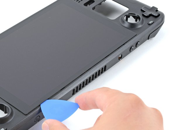
Heat the right edge of the display for one minute.
-
-
-
Slide the opening pick down the right edge to slice the adhesive.
-
-
-
Heat the bottom edge of the display for one minute.
-
-
-
Slide the opening pick across the bottom edge to slice the adhesive.
-
-
-
Heat the left edge of the display for one minute.
-
Slide the opening pick across the left edge to slice the adhesive.
-
-
-
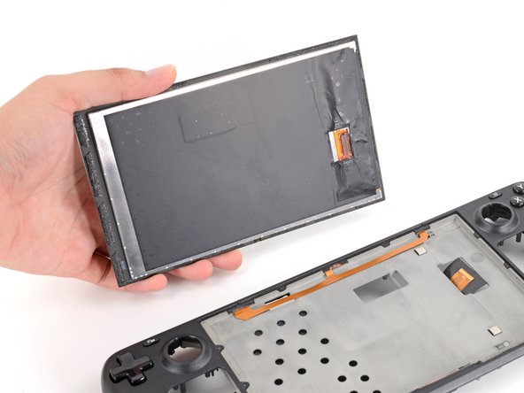
Once you have sliced around the perimeter of the display, carefully lift the right edge up, opening it like a book.
-
Remove the display.
-
-
-
Use a Phillips driver to remove the two 5.2 mm screws securing the left bumper assembly.
-
-
-
Remove the left bumper assembly.
-
-
-
Use a Phillips driver to remove the two 5.2 mm screws securing the right bumper assembly.
-
-
-
Remove the right bumper assembly.
-
-
-
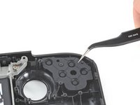
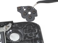
Use a pair of tweezers to remove the D-pad membrane.
-
-
-
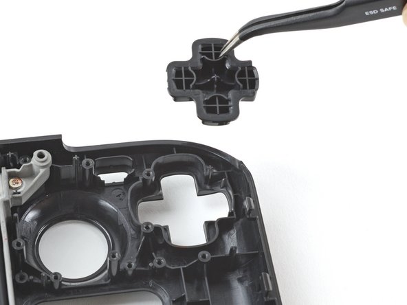
Use a pair of tweezers to remove the D-pad.
-
-
-
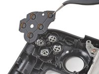
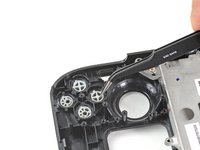
Use a pair of tweezers to remove the action buttons membrane.
-
-
-
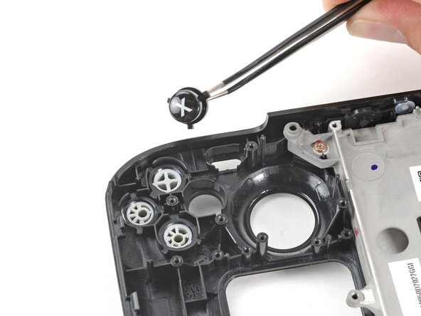
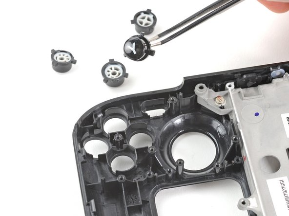
Use a pair of tweezers to remove the four action buttons, A, B, X, and Y.
-
-
-
Use a pair of tweezers to remove the view button.
-
-
-
Use a pair of tweezers to remove the menu button.
-
-
-
Use a Phillips driver to remove the six 2.3 mm screws securing the midframe to the front shell, located on the front side.
These things are pure hell. The love to fall off of magnetized screwdrivers at a slight vibration, and are tiny, difficult to find if they drop. I recommend a string magnet nearby to locate if they fall.
-
-
-
Use a Phillips driver to remove the four 5.2 mm screws securing the midframe to the front shell.
-
-
-
Remove the midframe.
-
-
-
Use the pointed end of a spudger to lift the rubber flap to the left of the volume buttons up and out of its plastic clip.
-
-
-
Use a pair of tweezers to remove the volume buttons by pulling them up and away from the front shell.
-
-
-
Use the pointed end of a spudger to lift the rubber flap to the right of the power button up and out of its plastic clip.
-
-
-
Use the pointed end of a spudger to lift the rubber flap to the left of the power button up and out of its plastic clip.
-
Remove the power button.
-
-
-
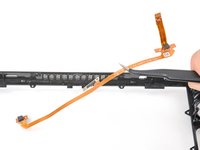
Insert the flat end of a spudger under the left end of the mic cable and pry upwards to peel it up from the front shell.
-
If the adhesive is stubborn, don't force the cable. Lightly heat the mic cable using an iOpener or a hair dryer to soften the adhesive.
-
-
-
Insert the flat end of a spudger under the right end of the mic cable and pry upwards to peel it up from the front shell.
-
If the adhesive is stubborn, don't force the cable. Lightly heat the mic cable using an iOpener or a hair dryer to soften the adhesive.
-
-
-
Remove the mic cable from the front shell.
-
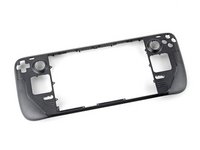
Only the front shell remains.
what will happen if the mic cable brakes?
cry
Not sure why,but now only the volume,power ,and touch screen works.
Note: so far already reimaged and downloaded newest drivers. Still doesn’t work so far.
With that being said i will update a fix if i find one.
Does the front shell come with adhesive for the screen? If not, where do I get adhesive to reattach the screen to the new front shell?
The front shell doesn't come with adhesive — screen adhesive can be found here. Happy fixing!
Can I know where to buy the mic cable?
-


To reassemble your device, follow these instructions in reverse order.
Take your e-waste to an R2 or e-Stewards certified recycler.
Repair didn’t go as planned? Try some basic troubleshooting, or ask our Steam Deck answers community for help.
To reassemble your device, follow these instructions in reverse order.
Take your e-waste to an R2 or e-Stewards certified recycler.
Repair didn’t go as planned? Try some basic troubleshooting, or ask our Steam Deck answers community for help.
crwdns2935221:0crwdne2935221:0
crwdns2935229:018crwdne2935229:0


crwdns2947412:020crwdne2947412:0
maybe I don’t need an Atomic Purple replacement shell…
Hahaha. Same
Rob -
Same, wouldn't have minded a sweet water dipped or translucent outer shell. Bring back that mad catz/third party aesthetic.
I wanted to replace my old shell with a new one cause it got scratches... well, now I feel the scratches ain't that ugly.
Seems to me like a "Welp...I guess if I ever break the screen and have to replace it, that's when I'll get an atomic purple shell...
I dropped mine and scratched it.... This seems to involve more than a simple screen replacement on my phones. I'll likely still order some spare parts just in case. With a baby on the way, they will likely break it and I want to be able to fix it quickly.
Fortunately, mine at the moment works. I should always close the hard case. Took it out of the car and didn't zip it up. Fell right out.
Just fell down the stairs and the joysticks damaged the top shell, but everything still works. After reading this, I think I'm going to live with it. Sheesh.
Great instructions, very easy to follow and precise. I followed it for the front face replacement but if you go all the way to remove the LCD it’s probably a good idea to purchase a new LCD and replace it as well. Removal of the LCD was the most troublesome and it’s possible to cause small separations of front glass from LCD, the LCD will probably work but the separation spots might be visible once same LCD is reused. Patience and following the instructions is the key here. Thank you for excellent instructions! 10/10 !
If you choose to replace/upgrade the screen as well, are you able to skip the step of taking the old screen off the front shell?
No, there are screws for the mid-plate behind the screen, see step 94
Will replacement speaker adhesive ever be available for purchase?
Shell swap would be cool for that Game Boy Color vibe...
Shell swap would mean broken Deck....
%#*@.
For Step #73, be careful when pulling back the sticker as it may tug the display connector out of the socket.
I was done at Step 18...instead of pushing that little guy up, I yanked on those cables like a moron...somehow I got that connector together again, thankfully.
Was trying to do a case swap...you know what, the old case is good enough for me :-)
I just realized I have a crack in the top bezel that extends into the fan exhaust area. Now I'm not nearly as bothered by it lol. If it craps out or truly breaks, I'll just get an OLED.
Given that I have exactly that flaw on a secondhand one... I wonder if it's structural. Maybe send a message to steam support to see if they'll handle it?
Hey guys, the trace of the central pin of my power button switch got ripped off the motherboard. Do you know where I can solder a jump wire from to the central pin of the power button? I hope I explained myself well
Very good guide. The instructions were clear and it made the process so easy. I really enjoyed following it and had lots of fun.
On a side note: Something worth adding to the part where you take off the screen display is that be careful running your pry pic along the top side because there is the mic cable there. I accidentally tore mine. Its a hard part to find a replacement for. I taped mine back together, and I don't use the mic, so I got away with it. But when they say don't insert the pic too far in, THEY MEAN IT.
For an unknown reason the atomic purple shell was sent back for a refund and the swap was never attempted. So weird. (I know my skill level 😅)
Guys, if you are going to attempt this - I recommend ordering left/right bumper button replacement too. Mine where broken (dunno in the process of disassembly or before). You won't want to wait for another delivery with half-assembled deck, trust me.