crwdns2915892:0crwdne2915892:0
Follow this guide to replace the front sensor array on your Samsung Galaxy Note9.
crwdns2942213:0crwdne2942213:0
-
-
Insert a SIM card eject tool straight into the hole in the SIM card tray.
-
Press to eject the SIM card tray.
 crwdns2952109:0crwdne2952109:0
-
-
-
Power off your phone before beginning disassembly.
-
Use a hairdryer, a heatgun, or prepare an iOpener and apply it to the right edge of the back of the phone for about a minute to soften the adhesive underneath.
-
-
-
Apply a suction handle to the back cover.
-
Lift with a suction handle to create a gap between the back cover and the frame of the phone.
-
Insert an opening pick into the gap.
-
-
-
Note that there is more adhesive along the top edge and around the camera bezel than around the rest of the phone.
-
Cut carefully around the left edge near the fingerprint sensor or you risk damaging the ribbon cable inside.
-
-
-
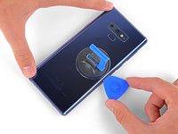
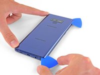
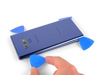
Starting from the center, cut the adhesive up and down the right side with an opening pick.
-
-
-
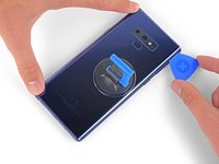
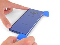
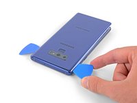
Leave an opening pick in the upper-right corner.
-
Use another opening pick to cut the adhesive around the bottom-right corner.
-
Leave that opening pick in the phone.
-
-
-
Use a heat gun or hair dryer or apply a heated iOpener to the left side of the rear panel for at three minutes to soften the adhesive underneath.
-
-
-
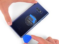
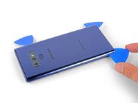
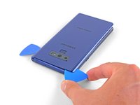
Insert an opening pick into the lower-left corner of the rear panel.
-
Using another opening pick, cut the adhesive along the left edge of the rear panel.
-
-
-
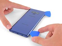
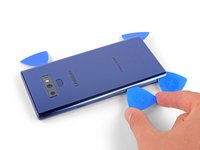
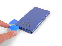
Using the inserted opening pick, carefully cut the adhesive around the upper-left corner of the rear panel.
-
Finally, cut the last of the adhesive along the top of the phone.
-
-
-
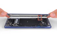
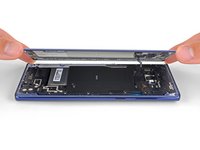
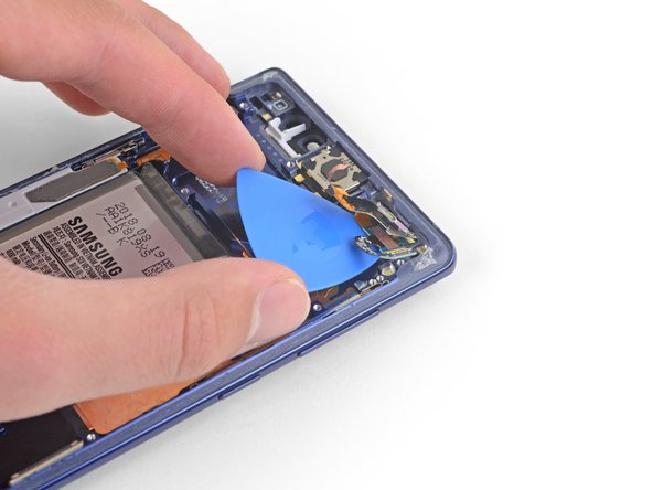
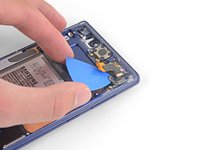
Separate the right side of the rear cover first.
-
Tilt the cover up along the left edge to expose the fingerprint sensor ribbon cable.
-
-
-
-
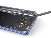
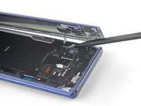
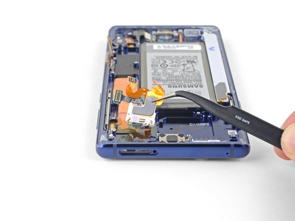
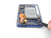
Use the tip of a spudger to pry the fingerprint sensor ribbon cable up and out of its socket.
-
-
crwdns2935267:0crwdne2935267:0Tweezers$4.99
-
Remove the back cover.
-
Use tweezers to peel away any remaining adhesive from the phone's chassis. Then clean the adhesion areas with high concentration isopropyl alcohol (at least 90%) and a lint-free cloth to prep the surface for the new adhesive. You don't have to clear out adhesive down to the plastic but larger pieces should be removed.
-
Turn on your phone and test your repair before installing new adhesive and resealing the phone.
-
Carefully apply the new adhesive to the back cover, then line up one edge of the glass against the phone chassis and firmly press the glass into the phone.
-
-
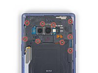
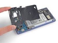
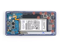
crwdns2931653:014crwdne2931653:0 Remove the upper midframe
crwdns2944590:014crwdnd2944590:017crwdnd2944590:0crwdnd2944590:0crwdne2944590:0
-
Use a Phillips screwdriver to remove the nine 4 mm screws securing the upper midframe.
-
-
-
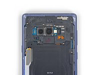
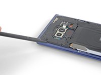
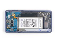
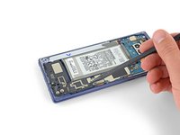
Insert the tip of a spudger into the upper-left corner of the upper midframe.
-
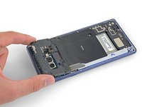
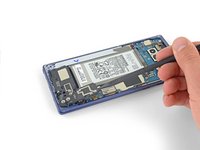
Pry the upper midframe out of the phone.
-
-
-
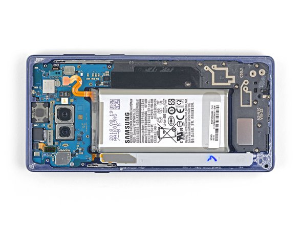
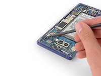
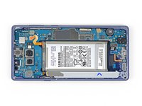
Peel the wireless charging coil off the battery starting with the left side.
-
-
-
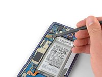
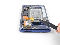
Use the tip of a spudger to disconnect the orange ribbon cable connecting the battery to the motherboard.
-
-
-
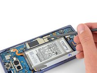
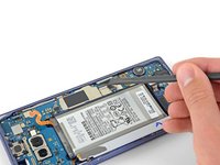
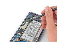
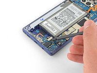
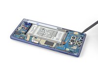
Remove the nine 4 mm Phillips screws from the plastic cover next to the battery.
-
-
-
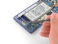
Remove the plastic cover next to the battery.
-
-
-
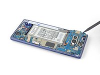
Insert the tip of a spudger into the top of the lower midframe.
-
Pry the lower midframe out from the phone.
-
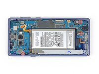
Remove the lower midframe.
-
-
crwdns2935267:0crwdne2935267:0Tweezers$4.99
-
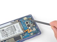
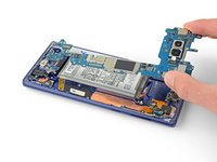
Use the tip of a spudger to pry the front camera connector straight up and out of its socket.
-
Use tweezers to remove the front camera.
-
-
-
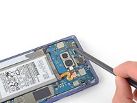
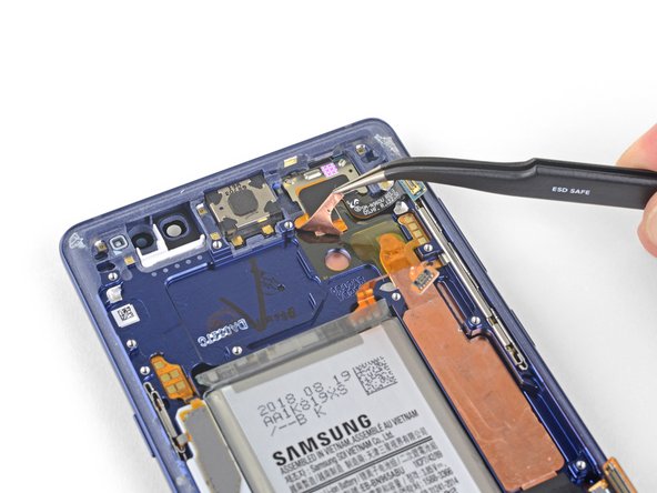
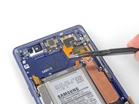
Use the tip of a spudger to disconnect the iris scanner from the motherboard.
-
Use tweezers to remove the iris scanner.
-
-
-
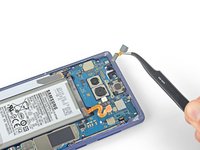
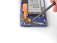
Use the flat end of a spudger to pry the front sensor connector out of its socket.
-
-
-
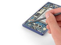
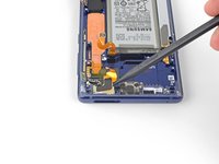
Use the flat end of a spudger to disconnect the display cable from the motherboard.
-
-
-
Use the flat end of a spudger to disconnect the touchscreen cable from the motherboard.
-
-
-
Use the flat end of a spudger to disconnect the charging assembly from the motherboard.
-
-
-
Remove the three 4 mm Phillips screws securing the motherboard.
-
-
-
Use a spudger to gently lift the motherbord from the upper-left corner.
-
Carefully remove the motherboard.
-
-
crwdns2935267:0crwdne2935267:0Tweezers$4.99
-
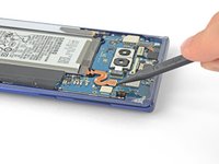
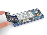
Use a pair of tweezers to peel back the adhesive-backed copper foil.
-
Stop peeling once you reach the sensor array.
-
-
-
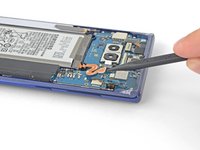
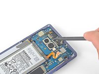
Use the tip of a spudger to lift the left side of the front sensor array and separate the adhesive the rest of the way.
-
-
-
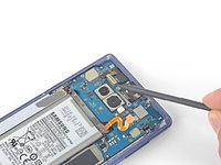
Carefully slide an opening pick under the front sensor array ribbon cable to cut the adhesive underneath.
-
-
-
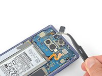
Use a pair of tweezers to remove the front sensor array.
-


To reassemble your device, follow the above steps in reverse order.
Take your e-waste to an R2 or e-Stewards certified recycler.
Repair didn’t go as planned? Check out our Answers community for troubleshooting help.
Compare your new replacement part to the original part—you may need to transfer remaining components or remove adhesive backings from the new part before installing.
crwdns2935221:0crwdne2935221:0
crwdns2935229:03crwdne2935229:0
