crwdns2915892:0crwdne2915892:0
Use this guide to replace the logic board in an Early 2020 MacBook Air.
Note that Touch ID will not function after replacing the logic board. The MacBook’s original Touch ID sensor is uniquely paired to the logic board at the factory—and without Apple’s proprietary calibration process, even a genuine replacement logic board from another MacBook Air won’t work.
If you replace the logic board, you must install a paired Touch ID sensor to retain Touch ID functionality.
crwdns2942213:0crwdne2942213:0
-
crwdns2935267:0crwdne2935267:0Magnetic Project Mat$19.95
-
If your MacBook is running Big Sur v11.1 or later, disabling Auto Boot may not work. You can proceed normally, but make sure to disconnect the battery as soon as you're inside.
-
Use a P5 driver to remove the following screws:
-
Two 7.9 mm screws
-
Two 7.1 mm screws
-
Six 2.6 mm screws
-
-
-
Wedge your fingers between the display and the lower case and pull upward to pop the lower case off the Air.
-
Remove the lower case.
-
Set it in place and press firmly to engage the two hidden clips underneath. You should feel and hear them snap into place.
When reassembling, the “snaps” are in the middle of the laptop (from top to bottom), and just to the left and right of center. I assumed it was near the hinge so it took a bit for me to hear the snaps.
Laurie, the two clips are outlined in the third photo of step two. Hope this helps—happy fixing!
What tool kit should I use for this?
the second picture is m1 air right?
the antenna cable position does not match later picture
-
-
-
Peel back the tape covering the battery connector enough to reveal the connector underneath.
This image is incorrect correct for the A2179 EMC 3302 model, also doesn’t match the next image in this guide
There is other guide for the model you reffer to, I was using that one until i realize it was different, this is the one you are looking for: MacBook Air 13" Retina Late 2020 (M1)
I initially thought the image was incorrect, but I was just looking for the connector in the wrong place. This picture IS correct for the A2179 EMC 3302. Note that the connector is on the left side of the heat sink (the black thing with parallel ridges in the picture and on the computer), and the connector wires gather together towards the left the side of the computer, not the back. Note that "left side" assumes the Air is upside-down, with the hinge on the side farthest away from you (I'm not doing the "right speaker is on the left side because it's upside-down" thing that iFixit does in step 5).
How do you find out if you have a Retina Late or Retina Early model?
-
-
-
Use a spudger to slide the battery connector parallel to the logic board and out of its socket on the logic board.
It’s stuck can’t get it out
Me too. It’s really stuck in there. Not sure if I should attempt the usb c port replacement if I can’t disconnect the battery.
Einfach abwechselnd links und rechts den Stecker langsam rausschieben. So wie abgebildet ist es tatsächlich schwierig.
-
-
-
Use a T4 Torx driver to remove the two 1.4 mm screws securing the trackpad cable cover.
-
Remove the trackpad cable cover.
-
-
-
Use the flat end of a spudger to pry the trackpad cable connector up and out of its socket.
-
-
-
Slide the pointed end of a spudger underneath the left speaker cable and pry straight up to disconnect it from the logic board.
-
With the connector disconnected, slide the flat end of a spudger under the cable to separate the adhesive securing the cable to the logic board.
-
-
-
crwdns2935267:0crwdne2935267:0Tweezers$4.99
-
Use a pair of tweezers to peel back any tape covering the microphone cable connector.
-
Use the pointed end of a spudger to lift up the small locking flap on the microphone cable's ZIF connector.
-
Slide the microphone cable out of its connector.
-
-
-
Use a T4 Torx driver to remove the two 1.4 mm screws securing the USB-C connector cover.
-
Remove the USB-C connector cover.
-
-
-
Use the flat end of a spudger to pry the USB-C cable connector up and out of its socket on the logic board.
-
-
-
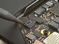
Use a spudger to lift up the small locking flap on the sound board cable's ZIF connector.
-
Slide the sound board cable out of the ZIF connector.
-
-
-
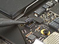
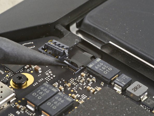
Peel back the black tape covering the fan cable connector.
-
-
-
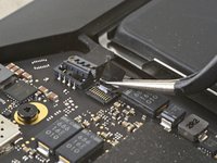
Use the tip of a spudger to lift up the locking flap on the fan cable's ZIF connector.
-
Slide the fan cable out of the ZIF connector.
-
-
-
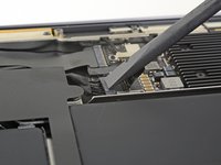
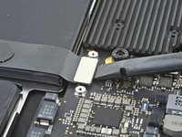
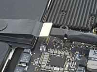
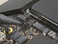
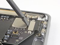
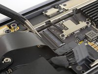
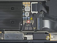
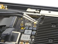
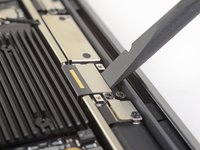
Use a T4 Torx driver to remove the 1.4 mm screw securing the antenna cable cover.
-
Remove the antenna cable cover.
-
-
-
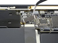
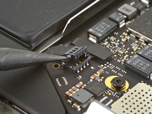
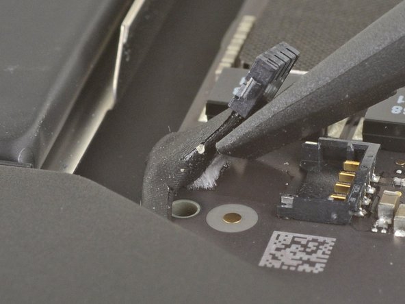
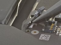
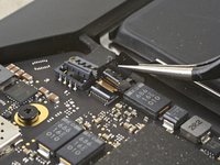
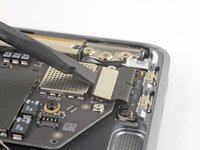
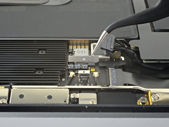
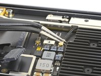
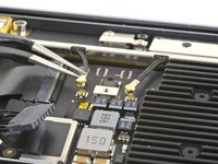
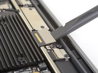
Use a pair of tweezers to grip the antenna connector close to its base.
-
Pull straight up to disconnect the cable.
-
Repeat for the second antenna cable.
-
-
-
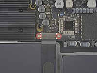
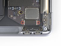
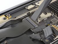
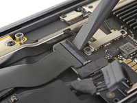
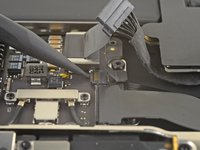
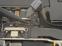
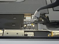
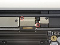
Use a T4 Torx driver to remove the two 1.5 mm screws securing the display cable connector cover.
-
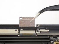
Remove the display cable connector cover.
-
-
-
Use the flat end of a spudger to pry the display cable connector straight off of the antenna board to disconnect it.
-
-
-
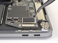
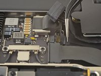
Use a T5 Torx driver to remove the six screws securing the logic board to the upper case:
-
Three 3.5 mm screws
-
One 5.8 mm cushioned screw
-
Two 2.0 mm screws
Hint: when reassembling, replace these 6 screws only about halfway so that the logic board can move about a bit. This will make aligning the logic board with the connector cables somewhat easier. Once all connector cables are in place, then tighten these screws starting from the innermost to the outermost.
-
-
-
Remove the logic board.
-
-
-
Battery cable
-
Fan cable
-
Audio board cable
-
USB-C board cable
-
Antenna bar cables
-
Trackpad cable
-
Left speaker and microphone cables
-


Compare your new replacement part to the original part—you may need to transfer remaining components or remove adhesive backings from the new part before installing.
To reassemble your device, follow the above steps in reverse order.
Take your e-waste to an R2 or e-Stewards certified recycler.
Repair didn’t go as planned? Check out our Answers community for troubleshooting help.
crwdns2935221:0crwdne2935221:0
crwdns2935229:015crwdne2935229:0


crwdns2947410:01crwdne2947410:0
donde se ubica disco duro , ya que ledi opcion borrar mac y maraca error desde recovery
P5 is also a PL4 (so confusing) - i like the wiha 26764 thanks to @mayer for this post. P5 pentalobe and 1.2 pentalobe screwdriver
greg - crwdns2934203:0crwdne2934203:0