crwdns2915892:0crwdne2915892:0
These instructions show how to dismantle the brew group of a Melitta Caffeo CI E970-101 if it has become jammed in the machine and can no longer be removed. The instructions are based on the type E970-101, but should also be helpful for other types.
crwdns2942213:0crwdne2942213:0
-
-
Depending on the problem, it may be necessary to remove the housing later. There are separate instructions for this, on here As a matter of fact, it is very likely that you will have to remove the housing.
-
-
-
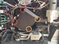
6 screws Tx15, marked red and orange, must be removed. Note that the screw with the orange marking is hidden under a clipped-in cover.
-
The screw with the green marking is also a Tx screw but a Tx10 screw. Move the lever to the position shown and remove the screw.
-
The second photo shows the removed screw cover. Remove that with a small flat screwdriver. Some of the plastic may break off.
-
Do not remove the plastic cover of the brew group yet, read the next step first.
-
-
-
In the photo you can see the bar on the lever and the groove on the brew group. Pry the lever out of the lower guide, then remove the lever at the upper end along the groove.
-
The cover of the brew unit can now be removed.
-
-
-
After removing the plastic cover, you can easily remove 3 parts. They may also fall out partially when the cover is removed.
-
Remove the marked parts and put them aside.
-
-
-
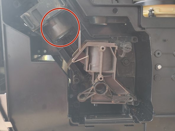
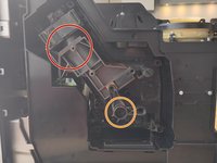
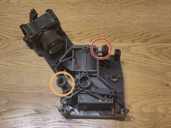
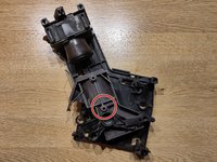
The chamber for the coffee powder is probably in the position shown in picture 1 (red circle). You can carefully try to move the brewing chamber downwards by turning the axle (orange circle) with slight force.
-
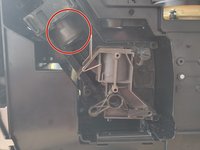
The first goal is to get into the position shown in picture 2. Also in picture 2 you can see the plunger that was in the brewing chamber (red circle).
-
If it is not possible to get the brewing chamber into the position shown in picture 2, then proceed to the next steps.
-
-
-
-
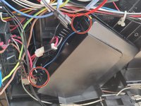
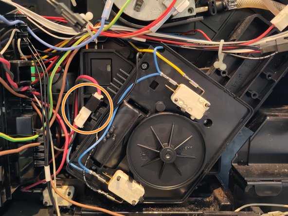
The black cover has 4 clips. Pry open the clips at the red mark, then the clips at the orange mark should be easy to open if you bend the cover slightly (Fig. 2).
-
To be on the safe side, take a photo of the position of the wheel, this could be important when reassembling.
-
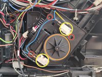
Pull off the wheel (Fig. 3, orange marking), it could be tight. The two white switches (Fig. 3, yellow marking) are each attached with 2 clips; loosen these.
-
Remove the 3 Tx10 screws (Fig. 3, red marking) and remove the plastic cover. Careful here since parts could fall out.
-
-
-
Various parts may fall out when opening. In particular, one of the axles may get stuck in the cover.
-
Also make sure that the small balls (red marking) are present.
-
Remove the gear wheel marked in orange.
-
The motor is now decoupled from the brewing unit and it should be possible to move the brewing unit.
-
-
-
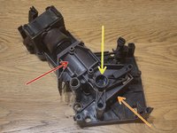
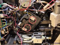
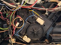
The coffee chamber (red arrow) can be in various positions. However, it cannot be removed in any position. Please compare both pictures in this step. The coffee chamber can also be so high that the upper sieve (top left in the picture) is not visible.
-
There are 2 adjustment options for the mechanism. Depending on the position, you need both or only one. There is the rotation axis (yellow arrow) and there is a tappet that is somewhat hidden (orange arrow).
-
Use these two adjustment options to set the mechanism so that it can be removed.
-
The second picture shows the position in which the brew group can be removed, including the rear part of the housing.
-
In the next step, you can see all the individual parts that you should then have. This might help with orientation.
-
-
-
This is just an overview of all the individual parts you have so far. The brew group has now been completely removed from the machine.
-
The clip that covered one of the screws is missing from the photo. The locking lever and all screws are also missing from the photo. You should also have these parts.
-
If you have more or fewer parts, or if there are still parts of the brew group in the machine, please go back to the instructions first to see what may have gone wrong.
-
There are instructions on iFixit and other sites on how to overhaul brew groups. You could look there for what else could be checked if you have already disassembled the brew group. It might be worthwhile, but it may not be necessary.
-
-
-
The first step is to insert the coffee chamber. The chamber can only be inserted in one position. See Fig. 1, paying particular attention to the red marking to ensure that the chamber is down to the stop. Now turn the chamber to the position shown in picture 2.
-
When the coffee chamber is in the correct position, turn the locking mechanism to the closed position (red circle, Fig. 2).
-
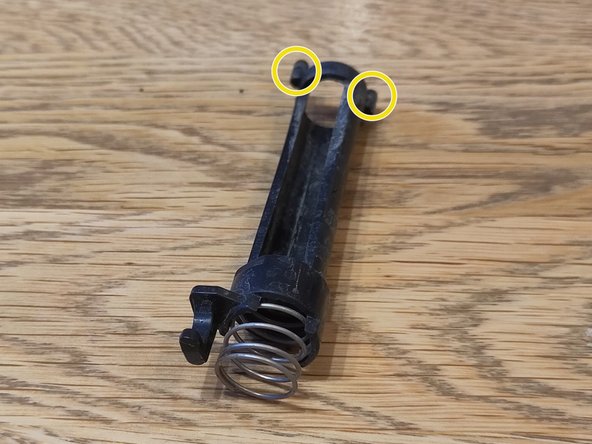
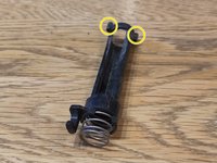
Now put on the bar (orange circle, Fig. 2). Pay attention to the two small pins (yellow circles, fig. 3). These must be inserted into the holes in the housing. There is only one correct position. Turn the bar 180 degrees and you'll see that the tiller is in the housing once and once not. Select the position in which the tiller is in the housing.
-
-
-
The coffee funnel has two ridges and the housing has a groove. Insert the bar of the funnel into the groove.
-
As the funnel (in the picture) has a bar at the top and bottom, it could also be inserted the wrong way around. Please pay attention to the orientation as shown in the picture.
-
-
-
Now screw the two halves of the housing together with the Torx screws.
-
Do not yet clip on the clip that covers one of the screws. This makes it easier to open everything again if something is wrong. Put the clip back on after the first few cups of coffee after the repair.
-
-
-
Next clip in the cover (red marking). Also clip in the locking lever (orange marking) in the "closed" position. Secure it to the axle again with a Torx screw.
-
The brew group should now be completely assembled (except for the cover of one screw).
-
-
-
The big question now is why the brew group was blocked and how to avoid this in the future.
-
One possibility is that the shaft connecting the motor and the brew group is slightly thicker at the point where it lies in the housing.
-
The shaft can only be removed if the motor box has been opened, see the optional steps above. Before removing the shaft, take a photo of both sides of the machine. The shaft can be removed from the motor side.
-
Sand down the plastic at the point marked in red with some sandpaper.
-
It is not necessarily visible to the eye whether it is really thicker. With the brew group removed and the motor decoupled, turn the shaft by hand. It should be relatively easy to turn.
-
-
-
Even if it can be inserted mechanically, it could be in the wrong position internally. It is advised to not place the machine into operation without further testing.
-
Figure 1 shows the basic position on the motor side. The black wheel has cams, please make sure that they are facing the switches as shown in the red circles in picture 1.
-
Disconnect the plug (orange circle in picture 2) and control the motor with 12V DC voltage. The voltage must be applied to the plug part which is still attached to the black housing. Plus/minus can be swapped for the forward and return of the motor. A 9V block battery may also be sufficient.
-
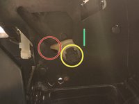
A certain position must be set on the side of the brewing group at the same time. The yellow circle shows the axis of the motor shaft. This has 3 grooves that engage in the white driver. This means that when the motor is in the basic position, there are only 3 different positions for the white driver.
-
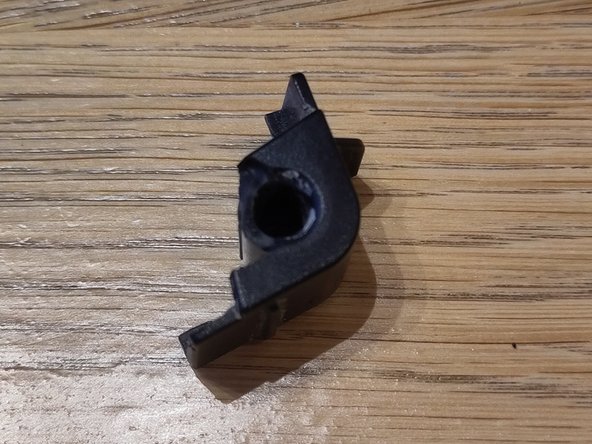
On the picture in the red circle you can see a hook, the actual driver. This position is not the basic position, it is only photographed so that you can see the hook. This hook must be in the approximate position of the green line.
-
It is important that the basic position on the motor side and on the brew group side prevail at the same time. Previously taken photos may help, otherwise try out the 3 possible (as there are 3 grooves) positions. Or pay attention to the photos here and already roughly align the axle when inserting it.
-


Work through the steps in reverse order to reassemble your device.
crwdns2935221:0crwdne2935221:0
crwdns2935229:02crwdne2935229:0
crwdns2934873:0crwdne2934873:0
100%

crwdns2934883:0oldturkey03crwdne2934883:0 crwdns2934875:0crwdne2934875:0
crwdns2934877:0crwdne2934877:0 ›
crwdns2947412:06crwdne2947412:0
Bravo für diese Anleitung! Ohne sie läge meine Caffeo jetzt auf dem Müll. Vielen Dank!
Hallo
Bei mir hat der Haken(Mitnehmer) in der Grundstellung eine komplett andere Lage. Die Brühgruppe lässt sich auch nicht einsetzen.
Was könnte das Problem sein?
Würde mich über Hilfe freuen.
Lh
Siehe Schritt 15, alle Teile müssen in der richtigen Position sein. Sprich auseinander bauen und wieder richtig einbauen. Insbesondere auf den grünen Strich achten im vierten Bild in Schritt 15.
kapott -
Absolut perfekt und eindeutig erklärt.
Vielen Dank
Claudia
Danke für die detaillierte Beschreibung. In meiner Maschine ist der Stecker für den Motor nicht vorhanden. Cafeo E960-106
Wie kann ich den Motor ansteuern?
Vg Monika