crwdns2933423:0crwdne2933423:0

Elektronik-Übungsbausatz MK112

crwdns2936315:0crwdne2936315:0
crwdns2936319:0crwdne2936319:0
crwdns2931653:04crwdne2931653:0
Electronics Skills Kit 101: crwdns2935265:00crwdnd2935265:01crwdnd2935265:02crwdne2935265:0 Electronics Skills Kit 101: crwdns2935265:00crwdnd2935265:02crwdnd2935265:02crwdne2935265:0
  • Place the leads of the resistor through the holes on either side of the rectangle marked R1 on the circuit board.

  • Resistors do not have to be installed in a particular orientation. Either lead can go into either hole.

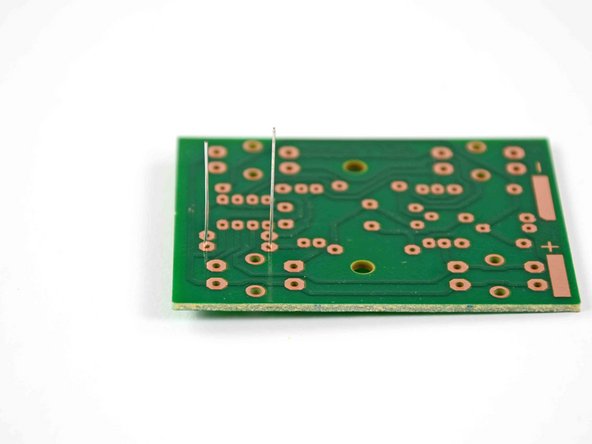
  • Turn the board over so that the copper traces are facing up and the resistor leads are pointing straight up in the air, as seen in the second picture.

  • You may also bend the leads outward to hold the resistor in place, but this is not necessary. As per NASA guidelines, any angle up to 30° down from vertical is acceptable.

Schiebe die Anschlussdrähte des Widerstands durch die Löcher auf jeder Seite des mit R1 markierten Rechtecks auf der Leiterplatte.

Bei Widerständen ist die Richtung egal, jeder Anschlussdraht kann in jedes Loch gehen.

Drehe die Leiterplatte um, so dass die Leiterbahnen aus Kupfer nach oben zeigen und die Anschlussdrähte des Widerstands nach oben herausragen, so wie in Bild 2 zu sehen.

Du kannst die Drähtchen auch etwas nach außen biegen, damit der Widerstand nicht herausrutscht, unbedingt notwendig ist das nicht. In den Richtlinien der NASA steht, dass jeder Winkel bis zu 30° erlaubt ist.

crwdns2944171:0crwdnd2944171:0crwdnd2944171:0crwdnd2944171:0crwdne2944171:0