crwdns2933423:0crwdne2933423:0

ProjectionDesign/Barco F35 regelmäßige Wartung

crwdns2936315:0crwdne2936315:0
crwdns2936319:0crwdne2936319:0
crwdns2931653:06crwdne2931653:0
projectiondesign F35 scheduled maintenance, Lamphouse and light path covers: crwdns2935265:00crwdnd2935265:01crwdnd2935265:03crwdne2935265:0 projectiondesign F35 scheduled maintenance, Lamphouse and light path covers: crwdns2935265:00crwdnd2935265:02crwdnd2935265:03crwdne2935265:0 projectiondesign F35 scheduled maintenance, Lamphouse and light path covers: crwdns2935265:00crwdnd2935265:03crwdnd2935265:03crwdne2935265:0
Lamphouse and light path covers
  • There are 2 ventilated metal covers here, held down by 7 screws total. The IO PCB does not have to come out, but makes it a little easier to reach the screws.

  • 4 screws in the color wheel /light path cover (at the top in the photo), and 3 in the lamp house cover (at bottom in photo).

  • If you choose to remove the IO PCB entirely, these 5 standoffs are where the PCB screws go.

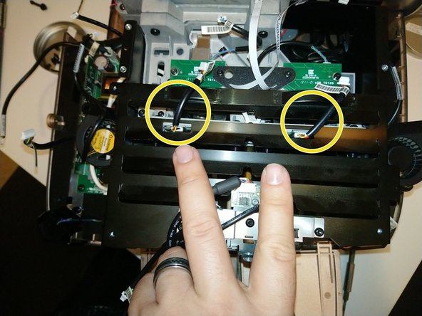
  • As you lift off the lamphouse cover, carefully work around these two wires -- for the lamp hour chip readers. They connect to boards below the cover -- it's probably better to leave them connected to the IO PCB, and unplug the connectors circled here instead.

  • The color wheel bracket is held down by just 3 T10 screws -- but they're about 14mm long and tricky -- especially the middle one, where you must reach through a hole in this black plastic gusset. I suggest using screwdriver with a magnetic tip here.

  • Once these 3 screws are removed, the color wheel bracket will be wobbly and loose. Lift it up carefully -- the wheels are very thin optical glass.

Hier sitzen zwei Metallabdeckungen mit Lüftungsschlitzen, die von insgesamt sieben Schrauben gehalten werden. Die IO-Platine zu entfernen hilft dabei, leichter an die Schrauben zu kommen, ist aber nicht zwangsweise erforderlich.

4 Schrauben in der Abdeckung des Farbrads/Lichttunnels (oben auf dem Foto) und 3 in der Abdeckung des Lampengehäuses (unten auf dem Foto).

Wenn du die IO-Platine vollständig ausbauen möchtest, werden die Schrauben der Platine in diese 5 Abstandshalter eingesetzt.

Beim Abheben der Lampenträgerabdeckung muss auf diese beiden Leitungen für die Lampenstunden-Chip-Leser geachtet werden. Es wird empfohlen, sie von auf der IO-Platine eingesteckt zu lassen und stattdessen die eingekreisten Stecker abzutrennen.

Die Halterung der Farbräder wird von drei T10 Schrauben gehalten, die jeweils etwa 14mm lang und knifflig zu entfernen sind. Die mittlere ist nur durch eine Öffnung in der schwarzen Kunststoffplatte zu erreichen, daher empfiehlt sich ein Schraubendreher mit langem Schaft und magnetischer Spitze.

Nach dem Entfernen dieser drei Schrauben kann der Farbradträger abgehoben werden. Sei dabei sehr vorsichtig, die Räder bestehen aus sehr dünnem optischem Glas.

crwdns2944171:0crwdnd2944171:0crwdnd2944171:0crwdnd2944171:0crwdne2944171:0