crwdns2933423:0crwdne2933423:0

ProjectionDesign/Barco F35 regelmäßige Wartung

crwdns2936315:0crwdne2936315:0
crwdns2936319:0crwdne2936319:0
crwdns2931653:05crwdne2931653:0
projectiondesign F35 scheduled maintenance, PCB IO (above light path): crwdns2935265:00crwdnd2935265:01crwdnd2935265:03crwdne2935265:0 projectiondesign F35 scheduled maintenance, PCB IO (above light path): crwdns2935265:00crwdnd2935265:02crwdnd2935265:03crwdne2935265:0 projectiondesign F35 scheduled maintenance, PCB IO (above light path): crwdns2935265:00crwdnd2935265:03crwdnd2935265:03crwdne2935265:0
PCB IO (above light path)
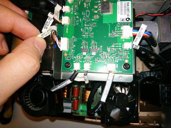
  • To reach the color wheels, we must remove the lamphouse cover. This PCB doesn't actually have to be removed, but all the wires going to it must be disconnected.

  • PD was very considerate in manufacturing these projectors -- there are labels on the cable and on the PCB connector.

  • Starting at the large ZIF ribbon cable, and naming them clockwise, we have: IO card ribbon cable, DC POWER IO, Fan Main, IR, Fan Ctrl VDI, Fan Lamp Driver, [lamp blower fan], Temp Lamp, Lamp Memory, Lamp 2 (switch), CW2, color wheel 2 ribbon, color wheel 1 ribbon, CW1, Lamp 1, Lamp Memory, Temp Out, [lamp 1 blower fan], Fan Lamp Driver, LMP Ctrl VDI, IR2

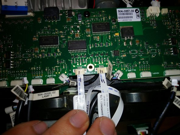
  • Well, most of my cables were well-labeled. Some, though, are close together enough and similar enough to possibly be confused. So, I suggest labeling connector and cable with marker to distinguish them. See example in pic 3 -- these are ribbon cables for the color wheel motors, and the 3-wire connectors for the position sensors.

Um Zugang zu den Farbrädern zu erlangen, muss zuerst das Gehäuse der Lampenträger entfernt werden. Diese Platine muss nicht unbedingt ausgebaut werden, aber alle Kabel, die zu ihr führen, müssen abgetrennt werden.

ProjectionDesign hat in der Produktion alle Leitungen und Steckverbinder auf der Verbindungsplatine beschriftet, was beim Zusammenbau hilft.

Beginnend mit dem großen ZIF-Flachbandkabel oben links im Uhrzeigersinn:

IO card Flachbandkabel, DC POWER IO, Fan Main, IR1, Fan Ctrl VDI, Fan Lamp Driver 2, [lamp 2 blower fan], Temp Lamp, Lamp Memory 2, Lamp 2 (Türschalter), CW2, Flachbandkabel Farbrad 2, Flachbandkabel Farbrad 1, CW1, Lamp 1 (Türschalter), Lamp Memory 1, Temp Out, [lamp 1 blower fan], Fan Lamp Driver 1, LMP Ctrl VDI, IR2

Die meisten Kabel sind gut beschriftet. Einige liegen jedoch nahe beieinander und sind sich so ähnlich, dass sie möglicherweise verwechselt werden können. Beschrifte daher Stecker und Kabel mit einem Marker. Siehe Beispiel in Bild 3 – dies sind Flachbandkabel für die Motoren des Farbrads und die dreipoligen Stecker für die Positionssensoren.

crwdns2944171:0crwdnd2944171:0crwdnd2944171:0crwdnd2944171:0crwdne2944171:0