crwdns2942213:0crwdne2942213:0
-
crwdns2935201:0crwdne2935201:0 crwdns2935203:0crwdne2935203:0
-
Unplug any cables and fully shut down your iPad.
-
-
crwdns2935201:0crwdne2935201:0 crwdns2935203:0crwdne2935203:0
-
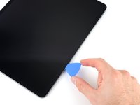
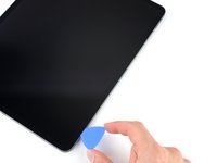
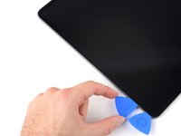
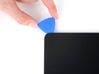
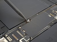
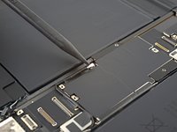
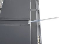
Apply a heated iOpener to the right edge of the screen for two minutes.
-
-
crwdns2935201:0crwdne2935201:0 crwdns2935203:0crwdne2935203:0
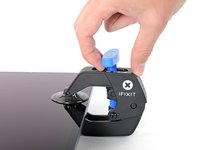
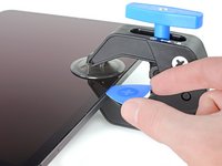
crwdns2935267:0crwdne2935267:0Clampy - Anti-Clamp$24.95-
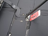
Pull the blue handle backwards to unlock the Anti-Clamp's arms.
-
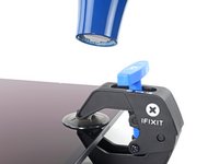
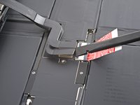
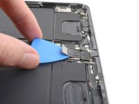
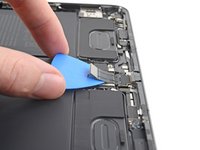
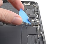
Place an object under your iPad so it rests level between the suction cups.
-
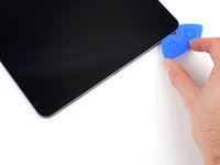
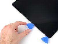
Position the suction cups near the middle of the right edge—one on the top, and one on the bottom.
-
Hold the bottom of the Anti-Clamp steady and firmly press down on the top cup to apply suction.
-
-
crwdns2935201:0crwdne2935201:0 crwdns2935203:0crwdne2935203:0
-
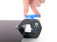
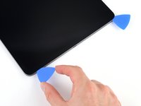
Pull the blue handle forward to lock the arms.
-
Turn the handle clockwise 360 degrees or until the cups start to stretch.
-
Make sure the suction cups remain aligned with each other. If they begin to slip out of alignment, loosen the suction cups slightly and realign the arms.
-
-
crwdns2935201:0crwdne2935201:0 crwdns2935203:0crwdne2935203:0
-
Wait one minute to give the adhesive a chance to release and present an opening gap.
-
If your screen isn't getting hot enough, you can use a hair dryer to heat along the right edge of the iPad.
-
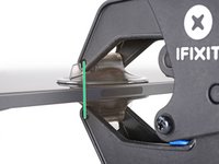
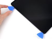
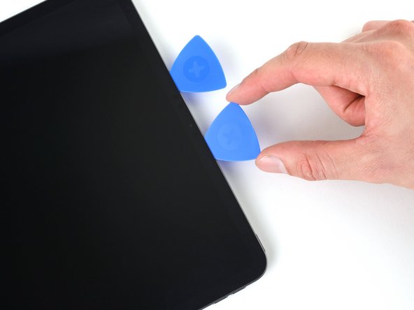
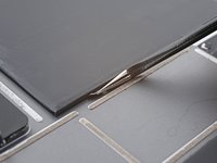
Insert an opening pick under the screen when the Anti-Clamp creates a large enough gap.
-
Skip the next step.
-
-
crwdns2935201:0crwdne2935201:0 crwdns2935203:0crwdne2935203:0
-
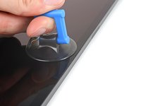
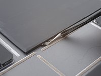
Apply a suction handle to the screen as close to the center of the right edge as possible.
-
Pull up on the suction handle with a strong, steady force to create a small gap between the frame and screen.
-
Insert an opening pick into the gap.
-
-
crwdns2935201:0crwdne2935201:0 crwdns2935203:0crwdne2935203:0
-
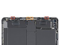
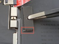
The first magnet begins 1.9 cm from the top of the iPad.
-
The second magnet begins 2.9 cm from the bottom of the iPad.
-
-
crwdns2935201:0crwdne2935201:0 crwdns2935203:0crwdne2935203:0
-
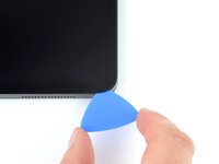
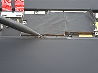
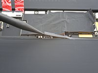
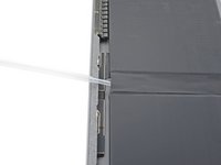
Slide your opening pick along the right edge of the screen to separate the adhesive.
-
Leave the pick inserted in the bottom right corner before continuing.
-
-
crwdns2935201:0crwdne2935201:0 crwdns2935203:0crwdne2935203:0
-
Slide your opening pick around the bottom right corner of the screen to separate the adhesive.
-
Leave your pick in the bottom right corner to prevent the adhesive from resealing.
-
-
crwdns2935201:0crwdne2935201:0 crwdns2935203:0crwdne2935203:0
-
Apply a heated iOpener to the bottom edge of the screen for two minutes.
-
-
crwdns2935201:0crwdne2935201:0 crwdns2935203:0crwdne2935203:0
-
Insert a second opening pick under the bottom right corner of the screen.
-
Slide your pick to the bottom left corner to separate the bottom adhesive.
-
-
crwdns2935201:0crwdne2935201:0 crwdns2935203:0crwdne2935203:0
-
Rotate your opening pick around the bottom left corner of the screen.
-
Leave your pick in the bottom left corner to prevent the adhesive from resealing.
-
-
crwdns2935201:0crwdne2935201:0 crwdns2935203:0crwdne2935203:0
-
Apply a heated iOpener to the left edge of the screen for two minutes.
-
-
crwdns2935201:0crwdne2935201:0 crwdns2935203:0crwdne2935203:0
-
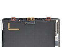
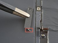
The 2.1-cm outer cutouts begin at 6.1 cm from the top and bottom of the frame.
-
The 2.8-cm inner cutouts begin at 10.1 cm from the top and bottom of the frame.
-
-
crwdns2935201:0crwdne2935201:0 crwdns2935203:0crwdne2935203:0
-
Insert a third opening pick under the bottom left corner of the screen.
-
Slide your pick to the top left corner to slice the left adhesive, making sure to avoid the cutouts shown in the previous step.
-
Leave the pick inserted in the top left corner before continuing.
-
-
crwdns2935201:0crwdne2935201:0 crwdns2935203:0crwdne2935203:0
-
Slide your opening pick around the top left corner of the screen.
-
Leave your pick in the top left corner to prevent the adhesive from resealing.
-
-
crwdns2935201:0crwdne2935201:0 crwdns2935203:0crwdne2935203:0
-
Apply a heated iOpener to the top edge of the screen for two minutes.
-
-
crwdns2935201:0crwdne2935201:0 crwdns2935203:0crwdne2935203:0
-
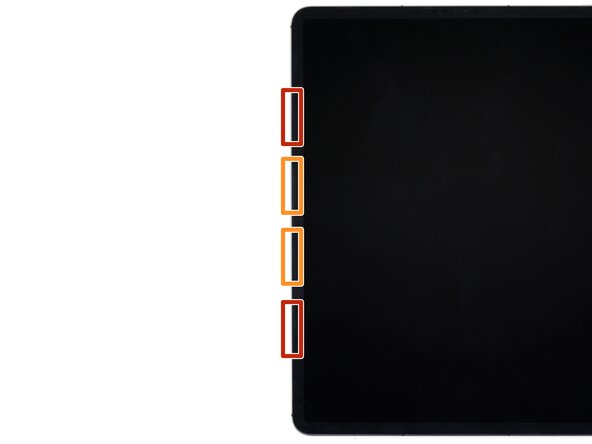
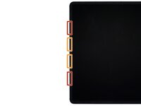
While the top edge adhesive softens, note the following:
-
There are 0.7-cm cutouts for the ambient light sensors starting 4.1 cm from each of the side edges. Don't insert your pick more than 1 mm here.
-
The front-facing camera and additional sensors are in the center of the top edge. Don't insert your pick here—there is less than 1 mm of adhesive and you may damage the components.
-
-
crwdns2935201:0crwdne2935201:0 crwdns2935203:0crwdne2935203:0
-
Slide your opening pick toward the top right edge, stopping just before the camera assembly.
-
Leave your pick inserted before continuing.
-
-
crwdns2935201:0crwdne2935201:0 crwdns2935203:0crwdne2935203:0
-
Insert a new opening pick on the other side of the camera assembly, about 4 cm from the previous pick.
-
Slide your pick to the top right corner to slice the remaining adhesive.
-
-
crwdns2935201:0crwdne2935201:0 crwdns2935203:0crwdne2935203:0
-
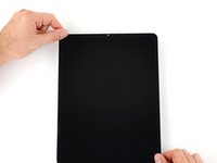
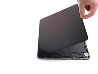
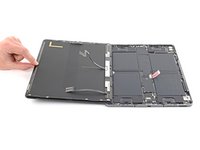
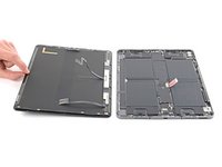
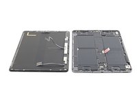
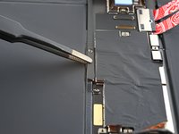
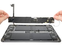
Grab two opposing corners of the screen and lift up to separate it from the frame.
-
Shift the screen towards the bottom right corner of the frame until the ribbon cable near the top edge is uncovered.
-
-
crwdns2935201:0crwdne2935201:0 crwdns2935203:0crwdne2935203:0
crwdns2935267:0crwdne2935267:0FixMat$31.41-
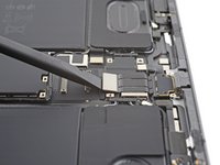
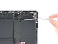
Use a Phillips screwdriver to remove the two screws securing the upper cable shield:
-
One 1.8 mm-long screw
-
One 1.4 mm-long screw
-
-
crwdns2935201:0crwdne2935201:0 crwdns2935203:0crwdne2935203:0
crwdns2935267:0crwdne2935267:0Tweezers$4.99-
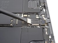
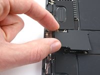
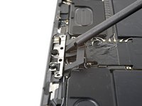
Use tweezers or your fingers to grab and remove the upper cable shield.
-
-
crwdns2935201:0crwdne2935201:0 crwdns2935203:0crwdne2935203:0
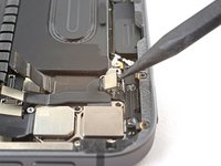
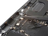
-
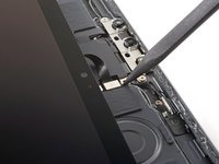
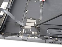
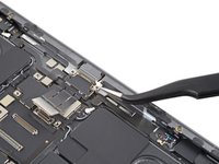
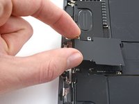
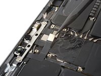
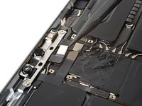
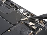
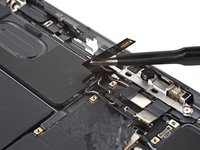
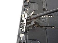
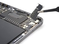
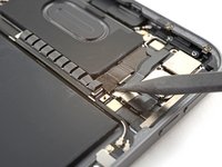
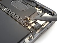
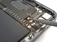
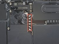
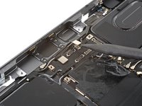
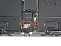
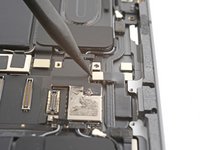
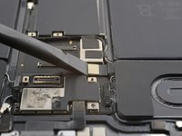
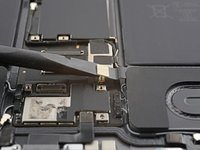
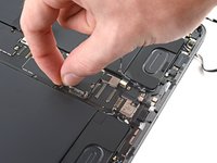
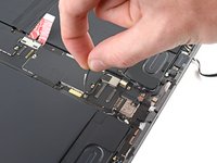
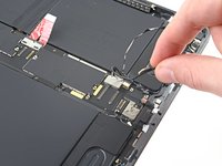
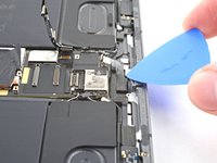
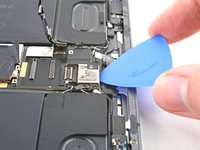
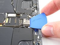
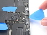
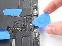
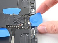
Use the tip of a spudger to pry up and disconnect the upper sensors press connector.
-
-
crwdns2935201:0crwdne2935201:0 crwdns2935203:0crwdne2935203:0
-
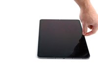
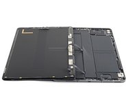
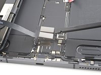
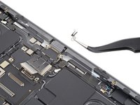
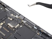
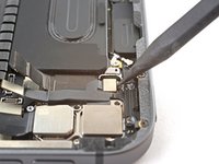
Grip the right edge of the screen and open it like a book.
-
Lay the screen down over the left edge of the iPad.
-
-
crwdns2935201:0crwdne2935201:0 crwdns2935203:0crwdne2935203:0
-
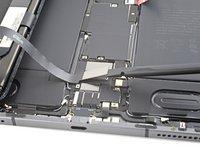
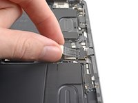
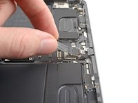
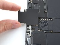
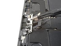
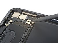
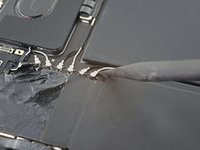
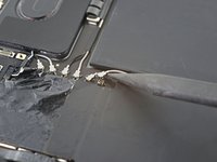
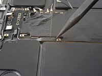
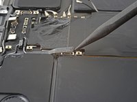
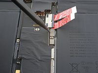
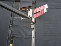
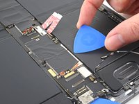
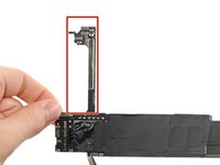
Peel the cover off of the logic board to remove it.
-
-
crwdns2935201:0crwdne2935201:0 crwdns2935203:0crwdne2935203:0
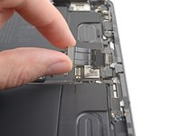
-
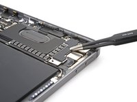
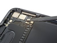
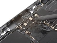
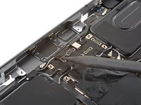
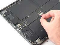
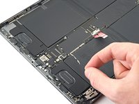
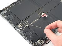
Use a Phillips screwdriver to remove the 1.7 mm-long screw securing the battery connector to the logic board.
-
-
crwdns2935201:0crwdne2935201:0 crwdns2935203:0crwdne2935203:0
-
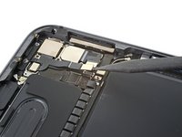
Use a Phillips screwdriver to remove the seven screws securing the top and bottom display brackets:
-
Four 1.1 mm-long screws
-
Two 2.0 mm-long screws
-
One 1.0 mm-long screw
-
-
crwdns2935201:0crwdne2935201:0 crwdns2935203:0crwdne2935203:0
crwdns2935267:0crwdne2935267:0Tweezers$4.99-
Use tweezers, or your fingers, to remove the top and bottom display brackets.
-
-
crwdns2935201:0crwdne2935201:0 crwdns2935203:0crwdne2935203:0
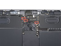
-
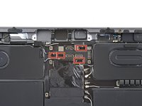
Use a spudger to pry up and disconnect the two bottom display cable press connectors.
-
-
crwdns2935201:0crwdne2935201:0 crwdns2935203:0crwdne2935203:0
-
Use a spudger to pry up and disconnect the two top display cable press connectors.
-
-
-
crwdns2935201:0crwdne2935201:0 crwdns2935203:0crwdne2935203:0
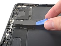
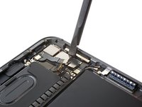
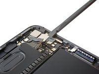
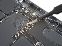
-
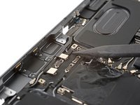
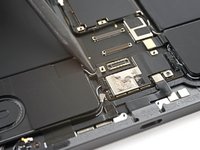
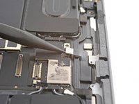
Use a spudger to pry up and disconnect the charging port cable press connector.
-
-
crwdns2935201:0crwdne2935201:0 crwdns2935203:0crwdne2935203:0
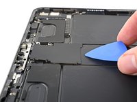
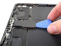
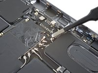
-
Insert an opening pick between the charging port cable and the logic board.
-
Slide the pick toward the charging port to separate the adhesive.
-
-
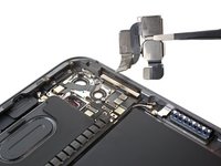
crwdns2935201:0crwdne2935201:0 crwdns2935203:0crwdne2935203:0
-
Use a Phillips screwdriver to remove the two 1.8 mm-long screws securing the charging port.
-
-
crwdns2935201:0crwdne2935201:0 crwdns2935203:0crwdne2935203:0
crwdns2935267:0crwdne2935267:0Tweezers$4.99-
Use tweezers to remove the two small grounding clips next to the charging port.
-
-
crwdns2935201:0crwdne2935201:0 crwdns2935203:0crwdne2935203:0
-
Use your fingers to pull the charging port out of its slot in the frame.
-
Remove the charging port.
-
-
crwdns2935201:0crwdne2935201:0 crwdns2935203:0crwdne2935203:0
-
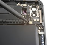
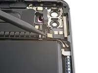
Use a Phillips screwdriver to remove the three screws securing the front camera bracket to the logic board:
-
Two 1.1 mm-long screws
-
One 1.0 mm-long screw
-
-
crwdns2935201:0crwdne2935201:0 crwdns2935203:0crwdne2935203:0
-
Heat an iOpener and apply it to the front camera bracket for two minutes.
-
-
crwdns2935201:0crwdne2935201:0 crwdns2935203:0crwdne2935203:0
-
Insert an opening pick between the front camera bracket and the logic board.
-
Slide the pick toward the top of the iPad to separate the adhesive.
-
-
crwdns2935201:0crwdne2935201:0 crwdns2935203:0crwdne2935203:0
-
Slide the front camera bracket toward the right edge of the iPad to release its metal clip.
-
Remove the front camera bracket.
-
-
crwdns2935201:0crwdne2935201:0 crwdns2935203:0crwdne2935203:0
-
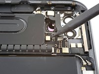
Use a spudger to pry up and disconnect the three front camera cable press connectors.
-
-
crwdns2935201:0crwdne2935201:0 crwdns2935203:0crwdne2935203:0
crwdns2935267:0crwdne2935267:0Tweezers$4.99-
Use tweezers, or your fingers, to peel the left-most cable off of the logic board.
-
-
crwdns2935201:0crwdne2935201:0 crwdns2935203:0crwdne2935203:0
-
Use a T3 Torx screwdriver to remove the two 2.2 mm-long screws securing the front camera.
-
-
crwdns2935201:0crwdne2935201:0 crwdns2935203:0crwdne2935203:0
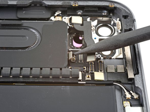
-
Insert a spudger underneath the front camera, between the middle and right cables.
-
Twist the spudger to separate the epoxy securing the front camera.
-
Remove the front camera.
-
-
crwdns2935201:0crwdne2935201:0 crwdns2935203:0crwdne2935203:0
-
Use a Phillips screwdriver to remove the five screws securing the rear camera bracket to the frame:
-
Two 1.2 mm-long screws
-
One 2.7 mm-long screw
-
One 2.6 mm-long screw
-
One 1.8 mm-long screw
-
-
crwdns2935201:0crwdne2935201:0 crwdns2935203:0crwdne2935203:0
crwdns2935267:0crwdne2935267:0Tweezers$4.99-
Use tweezers, or your fingers, to remove the rear camera bracket.
-
-
crwdns2935201:0crwdne2935201:0 crwdns2935203:0crwdne2935203:0
-
Use a spudger to pry up and disconnect the wide-angle camera cable press connector.
-
Disconnect the bottom power button cable press connector.
-
-
crwdns2935201:0crwdne2935201:0 crwdns2935203:0crwdne2935203:0
-
Use a spudger to pry up and disconnect the LiDAR sensor cable press connector.
-
Disconnect the ultrawide camera cable press connector.
-
-
crwdns2935201:0crwdne2935201:0 crwdns2935203:0crwdne2935203:0
-
Use a spudger to pry up and disconnect the top power button cable press connector.
-
-
crwdns2935201:0crwdne2935201:0 crwdns2935203:0crwdne2935203:0
-
Insert a spudger between the right edge of the rear camera assembly and the frame.
-
Pry up to separate the rear camera from the frame.
-
Remove the rear camera assembly.
-
-
crwdns2935201:0crwdne2935201:0 crwdns2935203:0crwdne2935203:0
-
Use the pointed end of a spudger to disconnect the six coaxial cables near the top of the iPad by prying up as close to their connectors as possible.
-
-
crwdns2935201:0crwdne2935201:0 crwdns2935203:0crwdne2935203:0
-
Use a spudger to pry up and disconnect the two top microphone press connectors.
-
-
crwdns2935201:0crwdne2935201:0 crwdns2935203:0crwdne2935203:0
-
Use the tip of a spudger to pry up and disconnect the four top speaker connectors.
-
-
crwdns2935201:0crwdne2935201:0 crwdns2935203:0crwdne2935203:0
crwdns2935267:0crwdne2935267:0Tweezers$4.99-
Use tweezers, or your fingers, to peel the three speaker cables off of the logic board.
-
-
crwdns2935201:0crwdne2935201:0 crwdns2935203:0crwdne2935203:0
-
Use a spudger to pry up and disconnect the 5G mmWave antenna press connector.
-
-
crwdns2935201:0crwdne2935201:0 crwdns2935203:0crwdne2935203:0
-
Use a spudger to pry up and disconnect the top right microphone press connector.
-
-
crwdns2935201:0crwdne2935201:0 crwdns2935203:0crwdne2935203:0
-
Use the tip of a spudger to pry up and disconnect the four bottom speaker connectors.
-
-
crwdns2935201:0crwdne2935201:0 crwdns2935203:0crwdne2935203:0
-
Use a spudger to pry up and disconnect the Smart Connector press connector.
-
-
crwdns2935201:0crwdne2935201:0 crwdns2935203:0crwdne2935203:0
-
Use a spudger to pry up and disconnect the SIM card reader press connector.
-
-
crwdns2935201:0crwdne2935201:0 crwdns2935203:0crwdne2935203:0
-
Use a spudger to pry up and disconnect the top antenna press connector.
-
-
crwdns2935201:0crwdne2935201:0 crwdns2935203:0crwdne2935203:0
-
Use the pointed end of a spudger to disconnect the Wi-Fi antenna coaxial cable by prying up as close to its connector as possible.
-
-
crwdns2935201:0crwdne2935201:0 crwdns2935203:0crwdne2935203:0
-
Peel the Wi-Fi cable towards the right edge of the iPad to separate it from the logic board.
-
-
crwdns2935201:0crwdne2935201:0 crwdns2935203:0crwdne2935203:0
-
Begin to peel the antenna cable along the right edge of the logic board.
-
-
crwdns2935201:0crwdne2935201:0 crwdns2935203:0crwdne2935203:0
-
Continue peeling the antenna cable until it completely separates from the right edge of the logic board.
-
-
crwdns2935201:0crwdne2935201:0 crwdns2935203:0crwdne2935203:0
-
Peel the 5G mmWave cable toward the right edge of the iPad to separate it from the logic board.
-
-
crwdns2935201:0crwdne2935201:0 crwdns2935203:0crwdne2935203:0
-
Use a Phillips screwdriver to remove the two screws securing the logic board brackets:
-
One 1.0 mm-long screw
-
One 1.1 mm-long screw
-
-
crwdns2935201:0crwdne2935201:0 crwdns2935203:0crwdne2935203:0
-
Slide the right bracket away from the logic board to release its metal locking clip.
-
Remove the right bracket.
-
-
crwdns2935201:0crwdne2935201:0 crwdns2935203:0crwdne2935203:0
-
Slide the left bracket away from the logic board to release its metal locking clip.
-
Remove the left bracket.
-
-
crwdns2935201:0crwdne2935201:0 crwdns2935203:0crwdne2935203:0
-
Use a spudger to pry up and disconnect the bottom left antenna press connector.
-
-
crwdns2935201:0crwdne2935201:0 crwdns2935203:0crwdne2935203:0
-
Use a spudger to pry up and disconnect the left microphone and Apple Pencil charger cable press connectors.
-
-
crwdns2935201:0crwdne2935201:0 crwdns2935203:0crwdne2935203:0
-
Apply high concentration (over 90%) isopropyl alcohol to the right edge of the logic board.
-
Tilt the right edge of the iPad upward to allow the isopropyl alcohol to work its way underneath the logic board.
-
Hold for one minute to allow the isopropyl alcohol to weaken the adhesive.
-
-
crwdns2935201:0crwdne2935201:0 crwdns2935203:0crwdne2935203:0
-
Slide an opening pick under the bottom edge of the logic board, near the charging port, to separate the bottom adhesive.
-
Leave the opening pick inserted to prevent the adhesive from resealing.
-
-
crwdns2935201:0crwdne2935201:0 crwdns2935203:0crwdne2935203:0
-
Insert an opening pick under the right edge of the logic board.
-
Slide the opening pick toward the battery connector to separate the right adhesive.
-
Leave the opening pick inserted next to the battery connector to prevent the adhesive from resealing.
-
-
crwdns2935201:0crwdne2935201:0 crwdns2935203:0crwdne2935203:0
-
Insert a third opening pick under the logic board on the other side of the battery connector.
-
Slide the opening pick toward the top of the iPad to separate the remaining right adhesive.
-
Leave the opening pick inserted to prevent the adhesive from resealing.
-
-
crwdns2935201:0crwdne2935201:0 crwdns2935203:0crwdne2935203:0
-
Insert an opening pick under the left edge of the logic board.
-
Slide the opening pick along the left edge to separate its adhesive.
-
Leave the opening pick inserted to prevent the adhesive from resealing.
-
-
crwdns2935201:0crwdne2935201:0 crwdns2935203:0crwdne2935203:0
-
Slide a fifth opening pick under the top edge of the logic board, near the front camera, to separate the top adhesive.
-
Leave the opening pick inserted to prevent the adhesive from resealing.
-
-
crwdns2935201:0crwdne2935201:0 crwdns2935203:0crwdne2935203:0
-
Apply high concentration (over 90%) isopropyl alcohol to the branch of the logic board.
-
-
crwdns2935201:0crwdne2935201:0 crwdns2935203:0crwdne2935203:0
-
Slide the top right opening pick along the top branch of the logic board to separate the remaining adhesive.
-
-
crwdns2935201:0crwdne2935201:0 crwdns2935203:0crwdne2935203:0
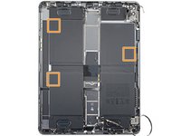
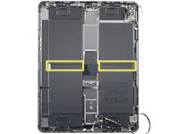
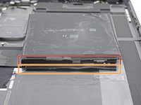
-
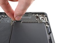
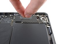
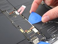
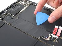
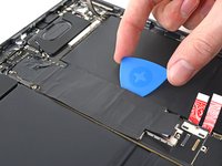
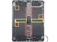
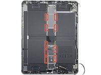
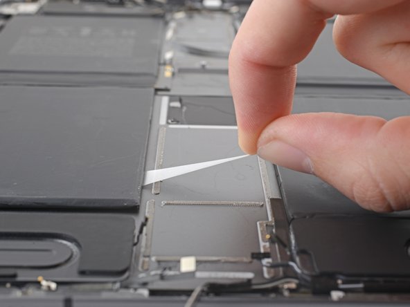
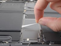
There are nine stretch-release adhesive pull tabs that have to be removed to separate the adhesive underneath the battery.
-
The corners of some of the battery cells have a small amount of extra adhesive that needs to be separated.
-
The remainder of the adhesive is located between the battery cells, underneath their battery boards.
-
-
crwdns2935201:0crwdne2935201:0 crwdns2935203:0crwdne2935203:0
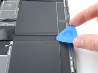
crwdns2935267:0crwdne2935267:0Tweezers$4.99-
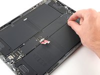
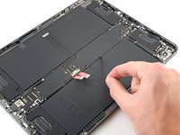
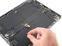
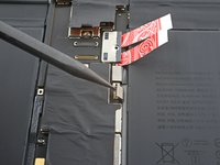
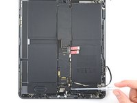
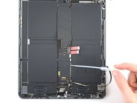
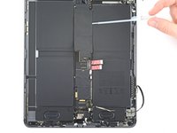
Use tweezers, or your fingers, to separate the pull tab from the battery enough so you can grab it with your fingers.
-
-
crwdns2935201:0crwdne2935201:0 crwdns2935203:0crwdne2935203:0
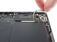
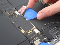
-
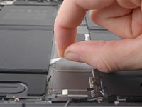
Pull the strip out slowly and steadily at a low angle. Give it plenty of time to stretch and un-stick from under the battery.
-
If the adhesive strip breaks off, try to retrieve it using your fingers or blunt tweezers, and continue pulling—but do not pry under the battery.
-
Repeat the process on all nine stretch-release adhesive strips.
-
-
crwdns2935201:0crwdne2935201:0 crwdns2935203:0crwdne2935203:0
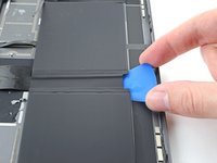
-
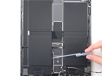
Apply high-strength (>90%) isopropyl alcohol along the edge of the battery.
-
Tilt the iPad to allow the isopropyl alcohol to work its way underneath the battery.
-
-
crwdns2935201:0crwdne2935201:0 crwdns2935203:0crwdne2935203:0
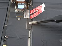
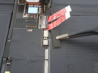
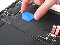
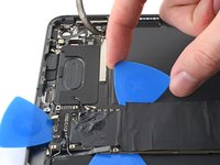
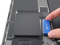
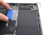
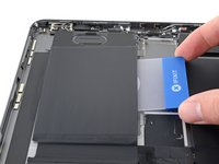
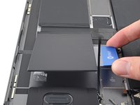
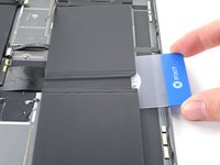
crwdns2935267:0crwdne2935267:0Plastic Cards$2.99-
Insert a plastic card into the gap between the battery and the frame.
-
Use the plastic card to slice the adhesive underneath the battery.
-
Repeat for each battery cell with remaining stretch-release adhesive.
-
-
crwdns2935201:0crwdne2935201:0 crwdns2935203:0crwdne2935203:0
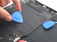
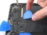
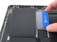
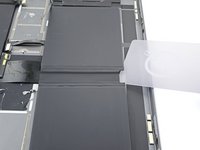
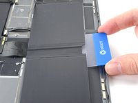
-
Insert a plastic card into the gap between the top right battery cell and the frame.
-
Use the plastic card to slice the adhesive underneath the battery.
-
-
crwdns2935201:0crwdne2935201:0 crwdns2935203:0crwdne2935203:0
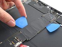
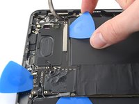
-
Insert a plastic card into the gap between the top left battery cell and the frame.
-
Use the plastic card to slice the adhesive underneath the battery.
-
-
crwdns2935201:0crwdne2935201:0 crwdns2935203:0crwdne2935203:0
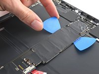
-
Insert a plastic card into the gap between the bottom left battery cell and the frame.
-
Use the plastic card to slice the adhesive underneath the battery.
-
-
crwdns2935201:0crwdne2935201:0 crwdns2935203:0crwdne2935203:0
-
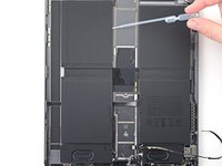
Apply high-strength (>90%) isopropyl alcohol to the battery boards between the cells.
-
-
crwdns2935201:0crwdne2935201:0 crwdns2935203:0crwdne2935203:0
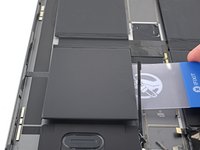
-
Don't slice between the battery and the board.
-
Slice between the board and the frame.
-
Insert an opening pick under the middle of the two battery cells to create an initial gap.
-
-
crwdns2935201:0crwdne2935201:0 crwdns2935203:0crwdne2935203:0
-
Insert the corner of a plastic card into the gap you just created.
-
Slide the plastic card under the battery board to separate its adhesive.
-
Repeat the slicing procedure for the other battery board.
-


crwdns2935221:0crwdne2935221:0
crwdns2935229:02crwdne2935229:0


crwdns2947410:01crwdne2947410:0
How to glue screen back? Can iPad work without battery-with power bank only? I hate battery problems -they grow inside-it’s make me feel stupid-like-idea to place them inside