crwdns2915892:0crwdne2915892:0
Use this guide to replace a faulty power supply in your iMac Intel 27" Retina 5K Display.
Before beginning any work on your iMac: Unplug the computer and press and hold the power button for ten seconds to discharge the power supply's capacitors.
Be very careful not to touch the capacitor leads or any exposed solder joints on the back of the power supply.
crwdns2942213:0crwdne2942213:0
-
crwdns2935267:0crwdne2935267:0iMac Intel 27" Cardboard Service Wedge$4.99
-
With the hinge free to move, the iMac will be unbalanced and hard to work on. Repairs can be completed with the iMac laying down, but are faster and easier with an iMac service wedge.
-
If you are using the iFixit cardboard service wedge, follow these assembly directions to put it together.
-
-
-
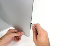
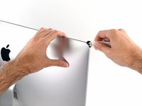
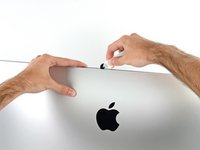
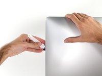
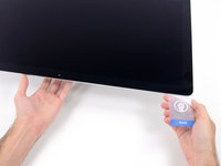
Starting on the left of the display, near the power button, insert the iMac Opening Tool into the gap between the glass panel and the rear case.
-
-
-
Use the tool like a pizza cutter—roll it along through the gap, and it will cut the foam adhesive through the center.
-
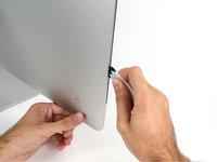
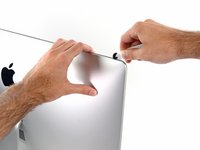
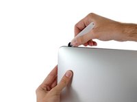
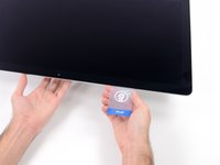
Run the tool up along the left side of the display.
-
-
-
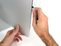
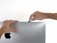
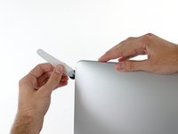
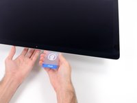
Continue wheeling the tool up around the top left corner.
-
-
-
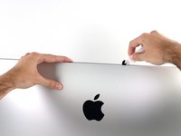
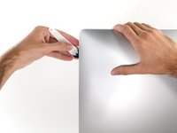
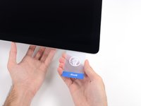
Cut the adhesive along the top left of the display.
-
-
-
Continue along the top of the display.
-
-
-
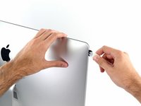
Push the tool around the top right corner of the display.
-
-
-
Wheel the tool down along the right side of the display.
-
-
-
Finish pushing the opening tool to the bottom of the right side of the display.
-
-
crwdns2935267:0crwdne2935267:0Plastic Cards$2.99
-
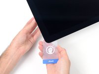
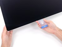
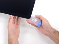
Set the iMac face-up on a table.
-
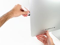
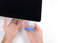
Starting from the top right corner of the iMac, insert a plastic card between the display and frame.
-
-
-
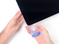
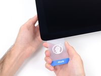
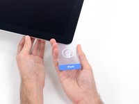
Gently twist the plastic card to open the space between the display and frame, and cut any remaining adhesive near the corner.
-
-
-
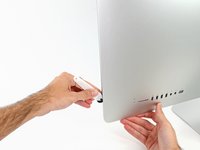
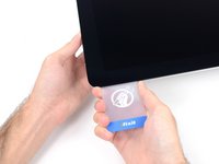
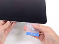
Slide the card toward the center of the display, to cut any remaining adhesive.
-
-
-
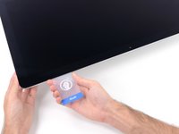
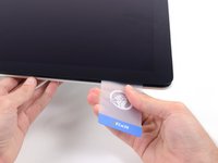
Put the card into the corner again and let it stay there to keep the adhesive from resettling.
-
-
-
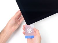
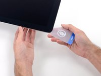
Insert a second card into the gap between the display and frame in the top left corner.
-
-
-
-
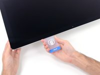
Gently twist the card, slightly increasing the space between the display and frame.
-
-
-
Slide the plastic card toward the center, again stopping just before the iSight camera.
-
-
-
Insert the card back into the top left corner.
-
-
-
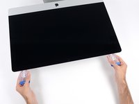
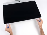
With the cards inserted as shown near the corners, gently twist the cards to increase the gap between display and case.
-
If there are any sections that seem to stick and won't separate, stop twisting and use one of the cards to cut the adhesive in the problem area.
-
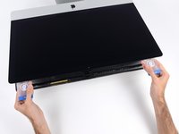
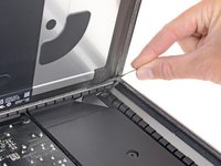
Begin to lift the top of the display up from the frame.
-
-
-
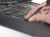
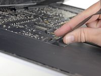
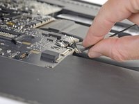
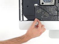
While holding the display up with one hand, use the other to unplug the display power cable.
Der Stecker muss seitlich wie die meisten anderen Stecker in diesem Modell komprimiert werden, um ihn aus der Buchse auf dem Logicboard zu ziehen. Die Zugrichtung ist parallel zum Logicboard in Richtung Oberkante des iMac. Ziehen ohne seitliches Zusammendrücken der Backen am Stecker könnte den Stecker oder die Buchse beschädigen.
These instructions are unclear. They imply the cable can just be pulled out but this step had me stuck for a bit. Searching the webs, I discovered that there are little tabs on either side of the connector. I used my prod tool and poked one side and the connector came out a little. I poked the other side the connector came out without a fight.
The instruction for this step state this but I was still not expecting two cables. Finally figured out there is a Display Power and a separate Display Data cable.
As others have mentioned later on, it is not necessary to fully remove the screen or disconnect these cables. I managed with just the screen held wedged open with a small cardboard box.
-
-
-
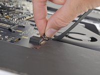
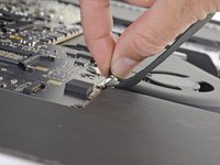
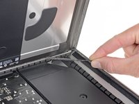
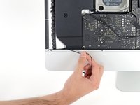
Flip up the metal retaining bracket on the display data cable.
-
Disconnect the display data cable.
-
-
-
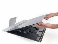
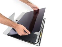
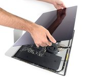
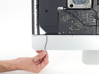
Lift the display up to a near-vertical position.
After rocking the display back and forth a bit, I found it helpful to use my iMac opening tool to gently slide ever so slightly underneath the bottom of the glass to cut the adhesive. This was with the display lowered back into it its normal position. I just worked about 1 millimetre deep at a time and eventually cut through the ~8” adhesive strip at the bottom centre.
It's possible to skip this step and go to step 24, leaving the display attached. You'll want to open the display just enough to replace the drive, with the machine upright and supported so the display doesn't swivel (I fold up a small pillow and wedge it in there). This way you don't have to worry about damaging the display when removing it, or aligning it when replacing it (which can be difficult to do solo as it's big and heavy).
Using a T8 with a short handle is helpful here, and make sure it's well magnetized so you don't drop the screws for the hard drive (just leave the other ones in the speakers).
-
-
-
Grasp the small tab at the end of one of the bottom edge display adhesive strips and pull the adhesive toward the top of the iMac to remove it.
-
Repeat this step with the other adhesive strip and remove it.
-
-
-
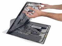
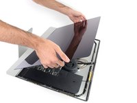
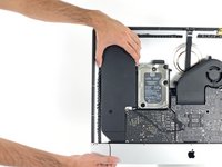
Lift the display up from the frame and remove it from the iMac. Lay the display face down on a flat, soft surface.
-
It may be necessary to slowly lift from one side, to peel against the remaining adhesive.
-
-
-
Use a Phillips screwdriver to remove the nine 3.2 mm screws securing the support bracket.
-
You may need to peel up the display adhesive lining the bottom edge of the iMac enclosure to access the screws.
These are new steps from when I did this on my late 2015 retina iMac so I believe step 25 and 26 are optional (you can cope without doing it).
I did not find it necessary to remove these screws and this bar
I lost these 8 during the reassemble. The manual tells I need eight 3.2mm screws.
Can anyone help to clarify what screws I need. I don't really understand this size. Is this M2x3mm?
-
-
-
Remove the lower support bracket (a.k.a. "chin strap") from the iMac enclosure.
No comments on this ?
It's quite possibly the most difficult part to put back in the entire process
The screws are tiny and the there is no easy way to line up the holes on the bracket with the screws
Having got this far - it wasn't even all that necessary to remove this part in the first place
Severe pain in the neck
After an hour of painstaking mess - I managed to get 7 out of the 9 back in
By that time I could care less about the remaining 2
With the right tools and technique, the bracket can easily be replaced in under a couple of minutes.
Use a screwdriver with a magnetized tip which frees up one hand and place a screw on the tip first.
Then line up the screw hole on just one end of the bracket and using a pair of tweezers from the side, hold the bracket in place while you put in the screw.
Next, do the same on the other end of the bracket. After that, all of the screws in the middle are quick to replace. I didn't really have to touch the bracket again after the end screws were in place.
Hope that helps someone else since removing this bracket does make later steps a bit easier.
I used Max Z tweezers technique but screwed one screw in at the end and then worked my way to the other end.
Max & Stephen are correct. Not difficult at all if you start at the right end (either end, probably, but I liked staying away from the power supply), and use a magnetic driver.
-
-
-
Remove two 10 mm T10 screws.
I found i didn’t need to remove the speaker nor the hard drive. In fact I managed to remove the old PSU without even removing the chin strap. However, to install the replacement PSU, I had to remove the chin strap. So I would say, remove the chin strap, but you can optionally leave the speaker and hard drive in.
While you do not need to fully remove the screws as once you loosen them a few turns the speaker becomes free. I found that after the removal of the speaker, I turned it over and popped the screws out as this made it easier to replace it later as I could see the alignment before putting the screws back in. If not you may be off a little and you do not want to force the screw back in.
I used a pill container that I got from Walgreens to hold all of the fasteners I removed during the disassembly process. The container has 14 compartments (individual compartments for each morning and evening of the week). I put a small piece of paper in the compartment with the fasteners to note the name and step of the procedure and the size of the tool I used. Hopefully this will be useful when I go to put it back together again.
-
-
-
Unplug the left speaker cable by pulling it straight up out of its socket on the logic board.
-
De-route the cable from the gap between the hard drive and logic board.
I didn’t unplug and de-route this cable. Later, Step 29, has you remove the left speaker. This isn’t necessary. If you can just move the speaker over to expose the hard drive mounting screws, so if you’re not going to remove the speaker, you don’t need to unplug it.
on the 2019 iMac, it is horizontal not vertical so pull it horizontally out.
-
-
-
Use a spudger to disconnect the power button connector from its socket on the logic board.
Can someone explain what are the solder joint? Or tell me what it looks it?
The silver spots on the circuit boards. You may not want to tackle this alone. If you touch these areas, you can possible get a shock -- harming you and your computer.
Robert -
there is no need to disconnect the speaker, just unscrew it and move aside slightly to reach the HDD screws (about 5mm) - if you want to replace just the main HDD
Take note of exactly what direction this tiny little wire was.
The connector has a plain black side and the other side you can see the 2 silver connectors.. the side you can see the 2 silver connectors faces the front.. the plain side is to the back/against the logic board.
If I leave my iMac unplugged for an extended period, say 24 or 48 hours, is it still possible to get an electric shock from the PSU? Do the capacitors eventually discharge?
you can do this method, or just wear latex gloves.
make sure you’ve actually unplugged the mac when running this cable, and not had it plugged in to test the diagnostic LEDs, because one of those wee silver spots is carrying 230v, and its 6mm away from the place the cable runs, So if you have fat fingers like mine, that’s a free wake up zap
I don't understand how people can say that you don't need to remove the speaker, unless all they were doing was replacing the SATA drive with a 2.5-inch SSD. If you're using this guide to replace the SSD on the back side of the logic board, you definitely need to remove all the components.
-
-
-
Lift the left speaker straight up, until the power button cable is exposed (about 0.5 inches).
This is MUCH easier to do if the support bracket along the bottom is removed first. See iMac Intel 21.5" Retina 4K Display (2017) Logic Board Replacement step 25.
Use a P00.
To replace it, introduce it like in the photo at the link to be able to hold the right most holes of the chassis and bracket. Replace the first screw, align the bracket to the horizontal and add the screws from right to left. Each one will bring up the next hole in the bracket close enough to screw through. Reverse those directions if you are a leftie.
-
-
-
Gently de-route the power button cable from its groove in the left speaker.
Pay attention: if pulling out the loudspeaker tear off the wire of the power button, Apple have not any service parts except for the whole rear housing!
This is MUCH easier to do if the support bracket along the bottom is removed first. See iMac Intel 21.5" Retina 4K Display (2017) Logic Board Replacement step 25.
Use a P00.
To replace it, introduce it like in the photo at the link to be able to hold the right most holes of the chassis and bracket. Replace the first screw, align the bracket to the horizontal and add the screws from right to left. Each one will bring up the next hole in the bracket close enough to screw through. Reverse those directions if you are a leftie.
-
-
-
Lift the left speaker straight up and remove it from the iMac.
-
Push from the connector end as you pull from the speaker end to thread the cable under the hard drive's right bracket.
I found it wasn't necessary to remove the speaker from the left side to remove the hard drive. You can remove the screws, and then slide it over to the left — giving more than enough room to access the hard drive.
me too. don't need to remove it if you only want to change the hd
Agreed, wast of time to fully remove the speaker.
It is difficult to remove the bottom of the speaker because it bends into the frame. Be careful to remove the power button cable, which also routes in a channel in the bottom of the speaker.
easier to remove the speakers if you unscrew the front ‘chin strap’ - 6/9 phillips screws that you can see in the picture hold that aluminum piece in place
Agree. This is MUCH easier to do if the support bracket along the bottom is removed first. See iMac Intel 21.5" Retina 4K Display (2017) Logic Board Replacement step 25.
Use a P00.
To replace it, introduce it like in the photo at the link to be able to hold the right most holes of the chassis and bracket. Replace the first screw, align the bracket to the horizontal and add the screws from right to left. Each one will bring up the next hole in the bracket close enough to screw through. Reverse those directions if you are a leftie.
The trick with removing the left speaker is that you have to slide it up toward the top of the iMac (continuing to de-route the power button cable carefully as you go) to get it out from under the chin before you lift it up to remove it.
-
-
-
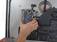
Pull straight up on the SATA data/power cable to disconnect it from the drive.
-
-
-
Remove two 7.3 mm T8 screws securing the left hard drive bracket to the rear case.
-
-
-
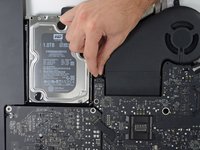
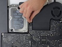
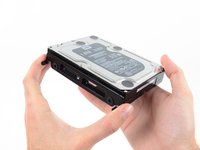
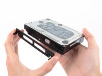
Grab the hard drive and left hard drive bracket together.
-
Tilt the left side up away from the rear case, and slide the assembly to the left.
-
Remove the hard drive and left hard drive bracket from the iMac.
-
-
-
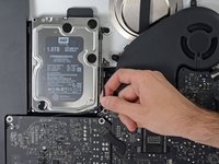
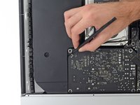
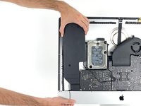
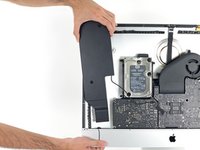
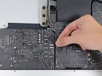
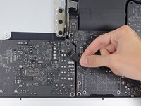
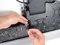
Disconnect the power supply control cable from the power supply.
I found this cable very difficult to disconnect, be very careful because the cable is between a black tape and it's stuck very hard to the logic board and the cable is very short and you don't have space to move and separate it from the connection! Be patient and take the time you need
I found than putting the flat end of the spudger at the center of the cable, and tilting it got the cable out without an issue.
I was able to use the flat end of the spudger on the sides. You can see a tiny little clip on each side. Be very gentle!
I simultaneously used the fingernails on my 2 index fingers to dislodge the tabs and continue to pull the cable out. It took a couple seconds.
ultimately the trick for me was to just pull hard enough, but that part is the scariest part. any tips welcome
These connectors seem pretty tough to remove until one understands the latch. Each side of the plug are two little sprung tabs (the tab is part of the spring clip which runs down the side of the plug on each side - makes sense once you see the removed plug!). Squeeze them in towards each other and then gently pull the plug from the socket. No great force, or even the spudger, needed once that is done.
One more tip, has worked on other cables for me. Fish the skinniest spudger tip you have under the cable, and with a finger of your other hand put opposite pressure on the cable against the spudger and gently work it out
If u are right handed, i can recomend to use your index left nail to press de bottom sprung, and a flat spudger on the right hand, came off so easy
Davo Montiel's tip worked for me. Use the fingernail on your left index finger to press in the tab on the bottom side of the connector and with the right hand use a flat spudger to press in the tab on the top side of the connector.
If you have a insulated long nose pliers along with a splugger and can get underneath the cable WITH the long nose pliers on the RIGHT side of the cable, towards the logic board, with the splugger on the LEFT Side of the cable doing the same, you can get the leverage to GENTLY pull this cable out very easily.
-
-
-
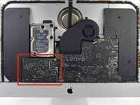
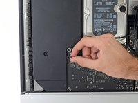
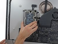
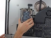
Remove the following four screws securing the power supply to the rear case (size T8 or T10 depending on the exact model):
-
Two 23.7 mm Torx screws
-
Two 7.3 mm Torx screws
-
-
-
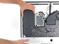
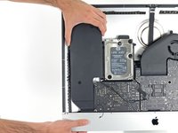
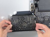
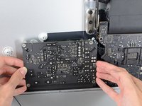
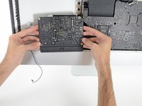
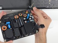
Move the power supply board towards the left edge of the case and up to free it from the notch in the logic board.
This is MUCH easier to do if the support bracket along the bottom is removed first. See iMac Intel 21.5" Retina 4K Display (2017) Logic Board Replacement step 25.
Use a P00.
To replace it, introduce it like in the photo at the link to be able to hold the right most holes of the chassis and bracket. Replace the first screw, align the bracket to the horizontal and add the screws from right to left. Each one will bring up the next hole in the bracket close enough to screw through. Reverse those directions if you are a leftie.
The top right screw on the power supply actually screws into a stand-off screw connected to the back of the iMac case. Once you have removed the 4 x Torx 8 or 10 screws you can move the power supply enough to see the upper face of it.
It has a Torx 25 slot in it and comes out easily. This will give you a lot more room for your fingers in Step 40, depressing the tab on the DC power cable connector to pull it out, and when replacing it on reassembly. You may find it won’t require you removing the support bracket as in the suggestion above.
-
-
-
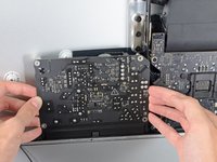
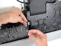
Depress the tab on the DC power cable connector, then pull it straight out of its socket on the back of the logic board.
Remember to push in the disconnect tab on the large connector. Carefully insert your finger and push on the tab before you pull on the connector.
Thank you Manuel, this was a tricky one.
Yes, I pulled the whole socket out because I didn’t know about the tab. Fortunately I was able to place it back in. Not sure if it was glued or how it was anchored but it seems to have a solid connection and I can’t easily pull it out by hand. Once I plug the power cable back in should be ok.
This connector was very difficult for me to remove (even after pushing the disconnect tab). Eventually I had to use a pair of needle nose pliers to wiggle it back and forth out of the socket. A lot of the cables on the my late 2015 model were very tight and a struggle to get out.
I'm struggling with this step. I presume that the tab to which you are referring is behind the connector. I can see a plastic protrusion there but it does not move when I push it. Just to get my finger behind it requires the power board to be moved quite a bit btw.
Pressing on the release on the back with my finger and at the same time using a needle nose pliers to wiggle the connector with my other hand worked for me.
i could not get it out by the force of my fingers, so what i did was slightly turn the imac 90 degrees so i could reach the area better, push up (so, vertically) the power control board, push in the tab on the bottom of the connector with my right hand, and slightly wiggle the connector out of its socket with a plier
removing the chin strap (the front bit of metal running along the bottom of where the screen was) makes this much easier as you can rotate the board and get to the underside
Left index finger pushing on the tab from behind the connector, using needle pliers in right hand to rock up & down did the trick thanks @starfleet_tone
Just be careful! I’ve seen two systems where the socket was pulled fully off! So the logic board then needs repairs or replacing being just a bit too aggressive!
Dan -
Needle nose and wiggling worked for us too. We were stuggling like heck with it when just using hands!
This is MUCH easier to do if the support bracket along the bottom is removed first - more space to angle the board upwards. See iMac Intel 21.5" Retina 4K Display (2017) Logic Board Replacement step 25.
Use a P00.
To replace it, introduce it like in the photo at the link to be able to hold the right most holes of the chassis and bracket. Replace the first screw, align the bracket to the horizontal and add the screws from right to left. Each one will bring up the next hole in the bracket close enough to screw through. Reverse those directions if you are a leftie.
I did as Andrew Gough did, per other videos reviewed. Removed it right away. Just makes things easier, more space for just a few screws :)
The top right screw on the power supply actually screws into a stand-off screw connected to the back of the iMac case. Once you have removed the 4 x Torx 8 or 10 screws you can move the power supply enough to see the upper face of it.
It has a Torx 25 slot in it and comes out easily. This will give you a lot more room for your fingers in Step 40, depressing the tab on the DC power cable connector to pull it out, and when replacing it on reassembly. You may find it won’t require you removing the support bracket as in the suggestion above.
I used your suggestion to remove the stand-off and then used my left hand index finger to press the tab while rocking the connector side to side with a needle nose pliers. Plug came out easily.
The tab is a pain in the a$$$ to get your finger in there. I was so horrified at the size of the capacitors that I put on gloves to reduce any amount of shock :-) . To get it loose I would pull out carefully the power board as far as I could than I wedge my index finger under and press the tab and slowly pull until I saw a slight gap between the end of the socket and the plug. I than place the flat part of the black spudger or blue one into the gap and use as it as a wedge to help move the plug forward as I kept the tab pressed.
-
-
-
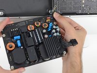
Flip the top of the power supply towards you, like opening a mailbox, to reveal the AC inlet cable connector.
-
Disconnect the AC inlet cable connector.
To reassemble, do the same in reverse but keep power supply board more upright than slanted down when re-inserting it in to the lower right corner. The lower right screw post has an protrusion under/behind it and the Power Supply's small 2 wire plug must fit between the front of your Mac and the obstruction. Then it just slides right in and then screw it down.
There is a small release tab on the cable.
Wear gloves when doing this to reduce any shock. The size of those capacitors are very unnerving and scary. Also those solder joints.
-


Compare your new replacement part to the original part—you may need to transfer remaining components or remove adhesive backings from the new part before installing.
To reassemble your device, follow the above steps in reverse order.
Take your e-waste to an R2 or e-Stewards certified recycler.
Repair didn’t go as planned? Check out our Answers community for troubleshooting help.
crwdns2935221:0crwdne2935221:0
crwdns2935229:08crwdne2935229:0

crwdns2947412:03crwdne2947412:0
I Will replace power supply iMac 2017 MNED2,
If i replace to power supply A1419 EMC 2639 can be working ?
Or i Must using A1419 EMC 3070 ?
Please advise . Thanks
Use heat to loosen the adhesive holding the screen or you might easily crack the screen as I did. Do not use prying tools without heat, and probably some IPA.
P.S. In the end, I managed to take off the screen using only pry tools and IPA without any additional damage to the screen. The screen crack seems to only affect the glass part on the edge, so the LCD display itself should still be fine. Some say heat can be dangerous and damage the LCD, so I decided to stick to IPA instead to soften the adhesive. In any case, just take your time: take it slow and be gentle. iMacs are not repair-friendly in the least.
What’s the point of this? You run the wheel around the outside, and then you lay it down anyway to pull the glass and do the rest. The wedge is not needed.
ebay - crwdns2934203:0crwdne2934203:0
I have a story to tell about this teardown. It all went wonderfully well until after I completed the process and attempted to format my new SSD drive only to discovery that the capacity of the drive was 256GB… not the 2TB I was sure I had ordered. iFixit was very supportive and helpful in sending me a new set of sticky tape strips and and RMA to return the SSD and some of the other parts.
I finally had received my new set of strips and the 2TB SSD…. I figured, piece of cake… I already know how to do this… but I watched the video again and started following the teardown…
…apparently the new sticky tape strips was way more powerful that the original tape and while using the pizza cutter tool and not advancing much, I proceeded to use one of the iFixit credit card style wedges…. I now have 2 pretty severe cracks on the glass of my display, which as clearly explained by @mayer can only be replaced by an entire display… which runs at about $500. Cosmetically it looks horrible, but it works… for now.
Erich Hentschel - crwdns2934203:0crwdne2934203:0