crwdns2915892:0crwdne2915892:0
As there is little to no information on how to replace a screen and/or battery for the Wahoo Elemnt Roam (WFCC4), I've created a rough guide based on my own experiences. I do hope that others will improve this guide in the future with more details and better information.
Opening the case and replacing the components is not for the faint of heart. Especially replacing the battery, requires some medium/advanced soldering and tools. Also, there are no spare parts readily available. So if you damage one of the components, such as the mainboard, or ribbon cables, you won't find a replacement.
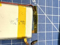
I also noticed that using a battery with a (slightly) different voltage, i.e. 3.7 instead of 3.8 Volts, screws with the battery algorithm in the software. The battery runtime is the same, for me even better than before, but it shuts off when still showing a 40% charge. So just keep that in mind.
crwdns2942213:0crwdne2942213:0
-
-
The unit consists of 3 main parts:
-
The bottom case, which holds the battery, USB charging port, as well as the rubber side buttons
-
The top case, which holds the mainboard, LEDs, and the top rubber buttons
-
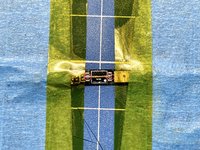
The screen which is glued to the top case and connected to the mainboard via two ribbon cables on the left hand side of the device
-
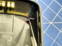
To soften the glue use a heat gun (at low heat) or hair dryer and heat up the edge of the top case
-
Use a small metal prying tool to pry open the device. This will take time and patience. The device is glued together like a tank!
-
-
-
Use a plastic spudger to remove the two ribbon cables that connect the USB port and the battery from the mainboard
Wissen sie wo man das interne USB C Anschluss Kabel mit den zwei kleinen Lautsprechern kaufen kann? Das ist bei mir defekt.
-
-
-
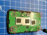
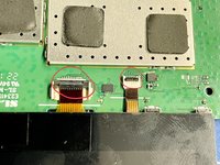
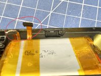
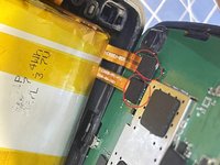
There are two ribbon cables that connect the screen and LEDs to the mainboard
-
Use a small pin / plastic spudger to lift up the black, plastic tabs that secure the ribbon cables in the connector (circled in red)
-
Carefully pull the ribbon cables out of the connectors
-
-
-
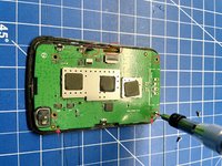
The mainboard is connected to the top of the case by four Torx 5 screws and held in place by two, small plastic guide pins in the top and bottom right corner (see arrows)
-
Use a Torx 5 bit and remove all of the screws
-
Ensure that you have removed the two ribbon cables connecting the screen and LEDs, before you remove the mainboard
-
After removing the mainboard, pull out the two white rubber bars for the LED lights.
-
-
-
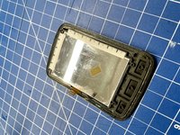
The screen is glued securely to the top of the case
-
Use a heatgun / hair dryer to soften the glue and use a small, thin prying tool to remove the screen from the top of the case
-
Again, this will take a lot of time and patience. Also, there's a very high chance that the screen will not survive this procedure. So be sure that you want to replace it before attempting to remove it
-
-
-
Remove the old glue from the top of the case and clean the surface
-
Add fresh glue and insert the new screen
-
-
-
Install the two white rubber bars to the top of the case
-
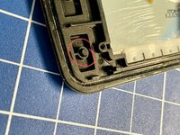
Be sure to add the three small, plastic extensions to the backside of the rubber buttons (red circle second picture). If you don't install these, the buttons won't work and you cannot add them later
-
-
-
-
Guide the two ribbon cables for the LEDs and screen through the cable guides on the left side of the mainboard
-
Ensure that the mainboard is positioned correctly and look out for the two guide pins in the top and lower right hand corners of the top case (see arrows)
-
Use a Torx 5 screw driver to screw in the four screws, fastening the mainboard to the top of the case (red circles)
-
Connect the two ribbon cables to the mainboard. Ensure that the black plastic tabs (red circles in the second picture), are in the up position before you insert the ribbon cables
-
Push down the two black plastic tabs (red circles in the second picture), to secure the ribbon cables
Gibt's evtl auch noch ein Bild der Platine, wo die USB Buchse zu sehen ist?
-
-
-
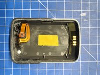
The battery is glued securely to the bottom of the case with double sided tape
-
Use a plastic spudger to carefully pry the old battery from the case. This will take some time and patience, as the double sided tape is very strong
-
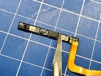
Remove the amber kapton tape and snip off the two main connectors to the battery circuit board
-
Dispose of the old battery in the right way and DO NOT throw it into the trash
-
Be careful when working with the battery and connectors and avoid creating a short between the two connectors
-
-
-
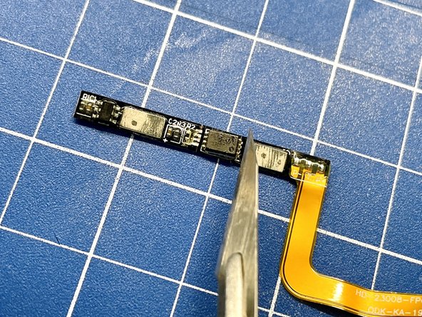
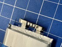
Although the new battery comes with its own circuit board, we'll have to use the old one as an intermediary / extension
-
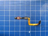
Remove the remaining pieces of the old battery connectors from the two main pads. Be careful not to rip off the pads from the circuit board.
-
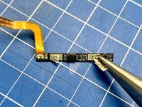
To avoid any conflicts between the logic of the old battery's IC and the IC of the new one, we have to remove the old one. Remove the small IC from the circuit board using an exacto knife or similar
-
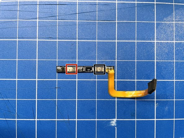
Use a soldering iron and some soldering wick to remove the remaining solder from the pads for the IC
-
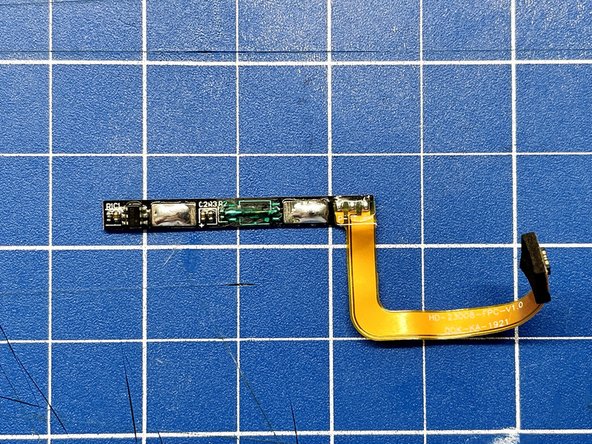
Note The pad to the left of the IC (U2) is for the positive side, and the pad to the right of the IC is for the negative side (see last picture for correct orientation)
-
-
-
We have to solder a bodge wire to create a permanent connection between the negative side of the old battery's circuit board and the ribbon cable.
-
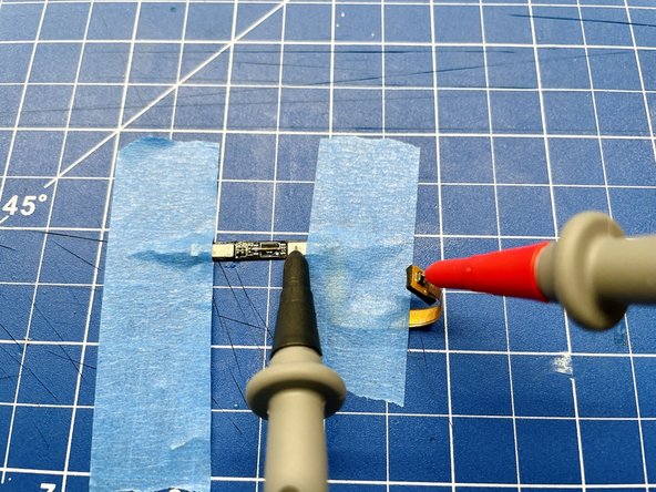
Solder a small enamelled copper wire to bridge the two center pads of the IC (red circles first picture)
-
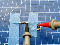
Use a multimeter to check the connection between the negative side of the circuit board and the ribbon cable
-
Add some solder to the positive and negative tabs of the board to prepare them for soldering later
-
You can also add some solder mask to the bodge wire for extra protection
-
-
-
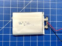
Remove the kapton tape securing the new battery's circuit board
-
Use a soldering iron to remove the attached wires from the circuit board's pads
-
Use a soldering iron and some soldering wick to clean up the pads
-
Add some fresh solder to the pads and solder two thin, flexible wires to the positive and negative tabs of the circuit board
-
Please take note of the wires' orientation. As you'll have to wrap the wires around the battery to fit the battery and wires into the case, solder them at an angle to make your life easier
You do know that soldering the battery pads for too long will wick heat into the battery and may melt the separator inside leading to an explosion, right?
yes, I know.
What do you mean by soldier 2 flexible wires to the board? Remove the red and black wires and immediately replace them with the same thing???
-
-
-
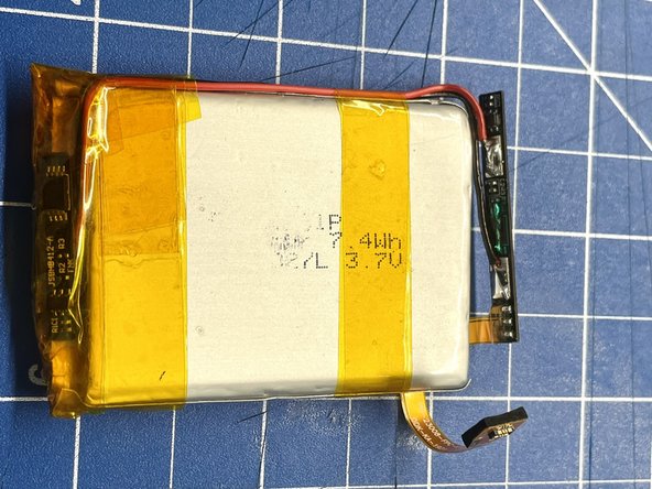
Fold the new battery's circuit board over and inwards
-
Use some kapton tape to secure the circuit board
-
Lead the wires around the side of the battery and secure them with kapton tape as well
-
Make sure the whole assembly is tightly packed and tidy to save space
-
Use a multimeter to check for the battery's voltage to ensure the wires are connected correctly and that there's no short
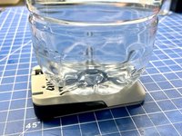
Hi! what is that white circle thing at the bottom left corner? i broke it do you think it matters?
Hi - I think it might be part of the ambient pressure sensor? It's not part of the electronics though, that's on the PCB, so it should work still, but your elevation data might be off? Just a guess
-
-
-
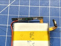
Solder the positive and negative leads to the pads of the old battery's circuit board, which we prepared earlier
-
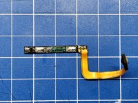
Please take note of the circuit board's and the ribbon cable's orientation. The ribbon cable has to run under the battery and then wrap around it, to ensure proper orientation with the connector on the mainboard
-
Wrap the circuit board in kapton tape and secure it closely to the battery, to create a tight and tidy package
-
Use a multimeter to check for voltage at the ribbon cable's end points, to check for a proper connection
-
-
-
Remove some material from the plastic tabs at the side of the bottom of the case to ensure that the new battery fits properly
-
Please take note of the orientation of the battery. The battery ribbon cable must be located in the lower half of the case, right next to the ribbon cable to the USB connector
-
This is a good time to connect the two halves of the case for a test fit to see that everything fits ok. If you need to squeeze too hard to get the two halves together, move the battery / cables / etc. to find a better fit
-
-
-
When you're happy with the fit, add some (thin!) double sided tape to the bottom of the case to secure the battery.
-
Reinstall the three plastic tabs for each of the side buttons.
-
Note Without the tabs the buttons won't work and they do have an orientation. So ensure that they are installed correctly.
Hi Bobbie,
Do you remember how the USB connector is mounted on the flat wire?
Is there a boad or is it sealed?
Mine is brocken and I want to figure out how to proceed.Thanks!
-
-
-
Connect the two ribbon cables for the USB connector and the battery to the mainboard
-
Press the Power button to test that the device starts correctly. Note: You'll have to directly press the small button on the left hand side of the mainboard to power up the device
-
Connect the device to a USB charger, to test that the device charges correctly
-
-
-
After you have tested the device successfully and confirmed that everything fits snug and tidy, you can glue the two halves back together
-
Add some glue to the small lip of the bottom half of the case that connects to the top half and press both halves together
-
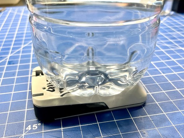
The best way to put pressure on both halves evenly, is to put the device upside down and to add some weight (e.g. a water bottle) on the backside of the device
-
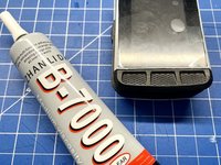
Note I have used B-7000 glue to reassemble the device and it has worked well so far. The device will encounter all sorts of weather conditions and temperatures, so you need some flexible glue that can cope with those conditions
-
-
-
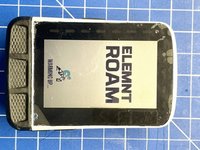
Remove the screen protector from the replacement screen and test the device fully
Bjr, ou puis je trouver un nouvel écran pour mon Wahoo Roam V1?
Vous pouvez le trouver sur AliExpress.
BenZ78 -
-


crwdns2935221:0crwdne2935221:0
crwdns2935229:09crwdne2935229:0

crwdns2947412:029crwdne2947412:0
Thank You. This it’s a good and a reasonable overview of why an electronic technician earns his money.
Good Job.
Muito obrigado pela explicação realmente tem pouco conteúdo sobre este assunto na Net
Is it possible to change top screen layer of gorilla glass w/o replacement of whole screen?
I tried with mine... And the glass is super glued to the screen under... Impossible to remove without shattering the panel underneath. I now have to buy a full new screen
Kennt jemand die Materialbezeichnung / um welchen Kunststoff handelt es sich beim Wahoo Elemnt Roam Gehäuse?
Danke!!
Hi, Many thanks for this very good guide. I just want to change the screen, is it possible to do it without opening the main case ?
Thanks for your answer.
Alain (from France)
Hi - there are two ribbon cables that connect the screen and LEDs to the backside of the mainboard (see step 3). The only way to get to them is by opening the main case. Thanks
I have the same question, my LCD is working fine and i have a replacement frame/glass only ordered from ebay. Can I just replace the glass without replacing the LCD hence only need to glue from the front and not have to open the main case?
WChu -
If all you need to do is to change the glass, you could try using a heat gun to soften the glue that holds the glass in place. However, from my experience, the LCD easily gets damaged during the process,
Hi, wouldn't it be easier to use the old circuit board intact with the new lipo (and removing completely the new circuit board) ?
There's no guarantee that the new battery will work with the old circuit board. At the same time you need the old circuit board for the proprietary ribbon cable. If you can get the battery to work with the old circuit board, then, yes, it'd be easier.
Hi by looking at different tutorials I think that keeping the new circuit board is probably safer anyway, due to the fact the original battery is 3,8v (so the cutting current is 4,35v vs 4,2v for a 3,7v battery, which is awy easier to source...) so I will follow your tutorial.
Thanks.
fosamax -
Good instructions, thank you very much! Question, do you think this battery will fit? It is a bit thick, but ships from the US:
Hi, I managed to successfully replace my battery thanks to your nice tutorial. I followed your advice to add a bodge wire to the original circuit and it works great so far. Autonomy seems OK but has not been tested extensively (I'm at 35 % battery ATM and it does'nt shut down so far).
Quite happy with the result for a GPS that was given to me at no cost since it was totally dead before battery replacement. Thanks.
Hi just a follow up. My unit shut down after getting as low as 2 percent charge. It may be a bit too late since I got a sad face logo when plugging my unit to charge. It eventually started to charge after a while but I think it may be a good idea to manually shut it down before to avoid any problem in the future.
fosamax -
Bobbie, would you be interested in replacing the screen on my Roam V1 if i shipped you the unit and of course paid you a fee $?
I simply dont trust myself not to screw it up ,
Let me know
cheers Paul
Eine tolle Anleitung, die ich mir aber leider nicht zutraue. Wäre jemand bereit den Akku meines Wahoo Roam zu tauschen?
Somebody located the usb replacement? USB-FD093-2.0 part.
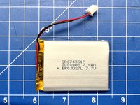
What’s the size of the original battery?
I can see 584158 in the label of the original battery which I think means 58mmx41mmx5.8mm.
I can confirm that it also matches the size I've measured of the battery I've removed (although it's hard to guess the last dimension as the battery is swollen).
Hola, Donde puedo conseguir el cable del conector usb?
I'm replacing a battery in Wahoo Roam v1, here are my tips and info:
First YOU SHOULDN'T USE 3.7 V BATTERY. Wahoo Roam V1 uses LiHV battery; 3.8 V nominal, 4.35 V charged. If you'll use standard 3.7 V cell, you'll decrease it's life, and risk another bulged battery. It won't explode or set itself on fire. The DW01A that is usually used on 3.7 V cells has OVP of 4.3 V ± 0.05 V (there are other versions with different OVP).
Do not remove the MOSFET "because there is already one", the more protection the better. Just weld / solder the terminals.
I'd say max cell size is around 654255.
The case is friction welded / CA glued, it's not "normal" glue; heat won't help, nor IPA. You need to breach through the weld with sharp tool, I've used a flathead screwdriver. There is a lip around the whole bottom part of the case, so you shouldn't be able to pierce through. I went through side buttons, but power button side should be better. After getting inside, I pried with thick metal spatula and lifted the case.
Do you have another battery to recommend? I'm finding it really hard to find 3.8v 2000mAh batteries of similar size.
I just got Roam V2 and you can buy batteries for it. I think it should fit directly without any modifications. Try searching for 564259 P93346103516
Oxmstr -
Hi, I worked through the guide to replace the internal battery. To open case was quite a challenge. After the replacement everything seems to work execpt the GPS signal. I did reset the device and took to out far from any buildings but it remains in the stage "searching". Any advise would help. Thanks.
I think the gps antenna is connected through 2 of the 4 pins you can see in the first picture of step 16. Maybe the pins are not making proper contact or misaligned?
Do you have to replace the screen with the battery? I would really like it if I didn't have to buy another screen if the one I have works great...
Thanks this is a good guide. I just replaced the battery of my roam. The glue is really though and I recommend soldering with good equipment (that is not a $15 soldering iron from a hobby shop:-) the glue is btw available in Europe. pretty easy.