
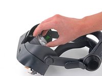
Valve Index Headset Eye Tube Replacement

crwdns2944109:0crwdnd2944109:0Sam Omiotekcrwdnd2944109:0crwdnd2944109:0crwdnd2944109:0crwdne2944109:0
crwdns2944111:0Nhl 18, 2025crwdne2944111:0
crwdns2915892:0crwdne2915892:0
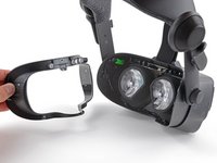
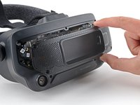
crwdns2942287:0crwdne2942287:0Follow this guide to replace one or both eye tubes on a Valve Index VR headset.
Power off and unplug your Index before you begin your repair.
Note: this is a cumbersome repair with small, loose components that may fall out during the process. Work slow, and carefully keep track of any pieces that fall out.
crwdns2942213:0crwdne2942213:0
crwdns2943213:0crwdne2943213:0


crwdns2943215:0crwdne2943215:0


crwdns2944105:0crwdne2944105:0

-
-
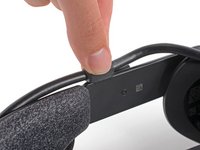
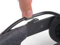
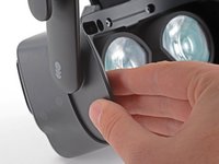
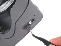
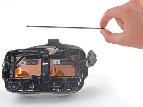
Twist the eye tube relief knob clockwise to fully extend it.
-
-
-
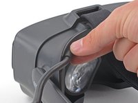
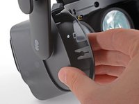
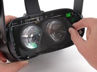
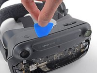
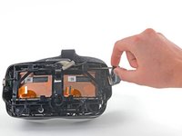
Use your hand to gently pull the face gasket straight off of the headset.
-
-
-
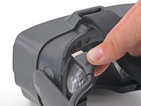
Insert the flat end of a spudger in between the bottom of the head strap clip and the head strap padding.
-
Pry up on the head strap clip until it is unclipped from the head strap.
-
-
-
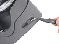
Use your fingers to pull the tether cable straight up off of the head strap cable guide.
-
-
-
Pull the tether cable straight back out of the headset.
-
-
-
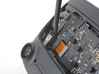
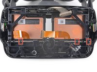
Use a T5 Torx screwdriver to remove the four 6.0 mm screws securing the face gasket bezel to the headset.
-
-
-
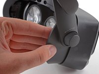
Grab the left edge of the face gasket bezel with your hand and slide it off of the headset.
-
-
-
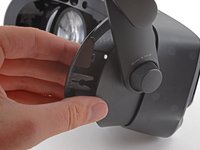
Repeat the previous step for the right side of the face gasket bezel.
-
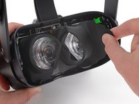
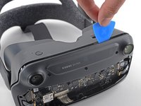
Remove the face gasket bezel.
-
-
crwdns2935267:0crwdne2935267:0Tweezers$4.99
-
Use a pair of tweezers to separate the left edge of the eye tube gasket from the headset.
-
Repeat the process for the right edge of the gasket.
-
-
-
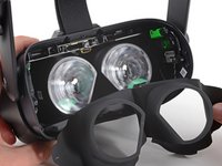
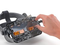
Gently peel the eye tube gasket out of the headset.
-
-
-
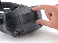
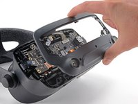
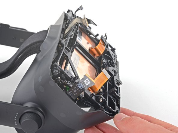
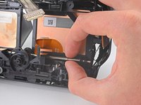
Use your hand to pull the front cover straight off of the front of the headset.
-
-
-
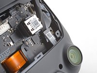
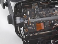
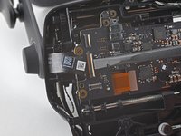
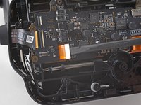
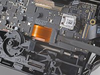
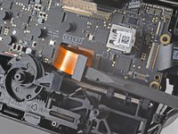
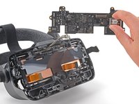
Use a T5 Torx screwdriver to remove the four 5.4 mm screws securing the motherboard cover to the headset.
-
-
-
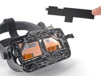
Remove the motherboard cover from the headset.
-
-
-
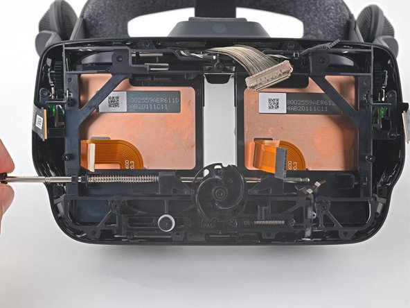
Use a T5 Torx screwdriver to remove the following eight screws from the front fascia:
-
Four 6.3 mm screws with fine threads
-
Four 6.0 mm screws with coarse threads
-
-
-
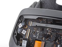
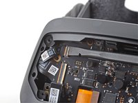
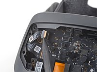
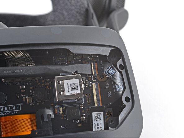
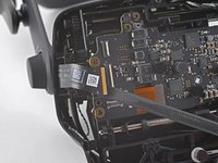
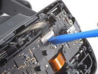
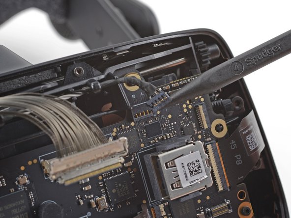
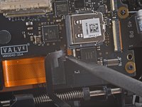
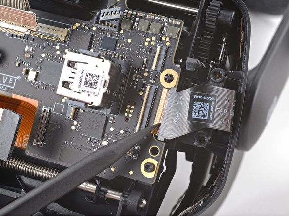
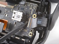
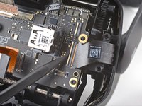
Use a spudger to unlock the ZIF connector at the top-left corner of the motherboard.
-
Disconnect the FPC ribbon cable from the motherboard.
-
-
-
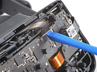
Use a spudger to unlock the ZIF connector at the top-right corner of the motherboard.
-
Disconnect the FPC ribbon cable.
-
-
-
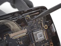
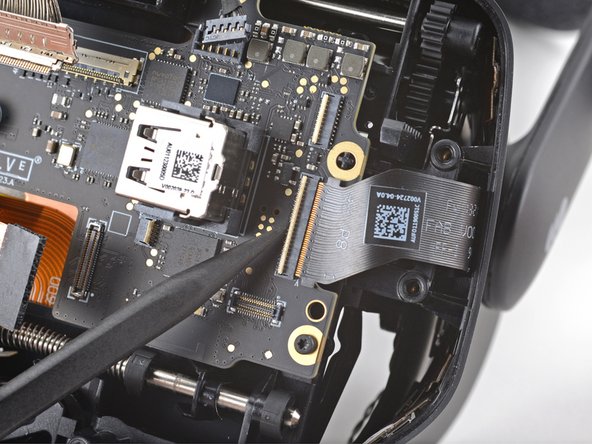
Use the flat end of a spudger to disconnect the press connector from the bottom-left corner of the motherboard.
-
-
-
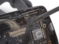
Use the flat end of a spudger to disconnect the press connector from the bottom-right corner of the motherboard.
-
-
-
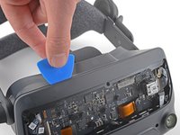
Insert an opening pick in between the front fascia and the headset.
-
Slide the opening pick over to separate the front fascia from the headset.
-
-
-
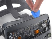
Continue sliding the opening pick along the perimeter of the front fascia until all edges are free.
-
-
-
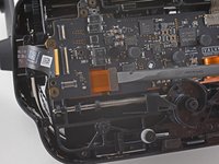
Note the seven cables that must be disconnected in the following steps before the motherboard can be removed.
-
-
-
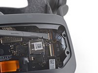
Use the flat end of a spudger to unlock the wide ZIF connector on the left side of the motherboard.
-
Disconnect the FPC ribbon cable from the motherboard.
-
-
-
Use the flat end of a spudger to disconnect the press connector near the bottom-left edge of the motherboard.
-
-
-
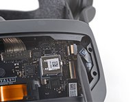
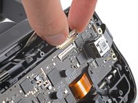
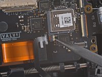
Use your finger or an opening tool to unlock the display cable connector at the top of the motherboard.
-
Carefully disconnect the display cable connector.
-
-
-
Use the pointed end of a spudger to gently disconnect the bundled cable connector from the top-right corner of the motherboard.
-
-
-
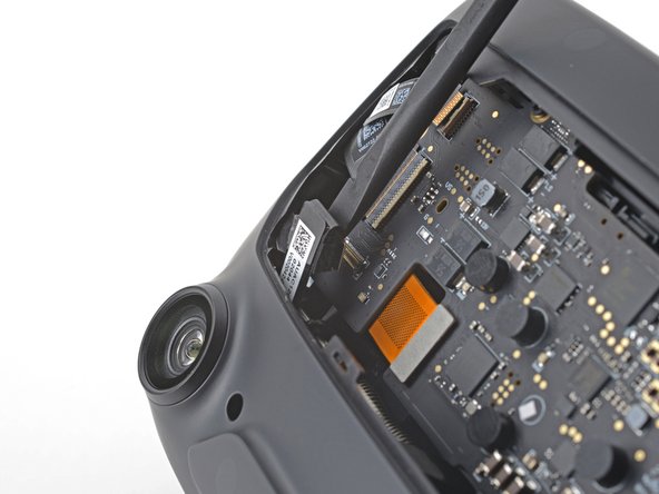
Use the pointed end of a spudger to unlock the ZIF connector next to the USB port on the motherboard.
-
Disconnect the FPC cable from the motherboard.
-
-
-
Use the flat end of a spudger to disconnect the press connector below the USB port on the motherboard.
-
-
-
Use a spudger to unlock the wide ZIF connector near the right edge of the motherboard.
-
Disconnect the FPC ribbon cable from the motherboard.
-
-
-
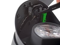
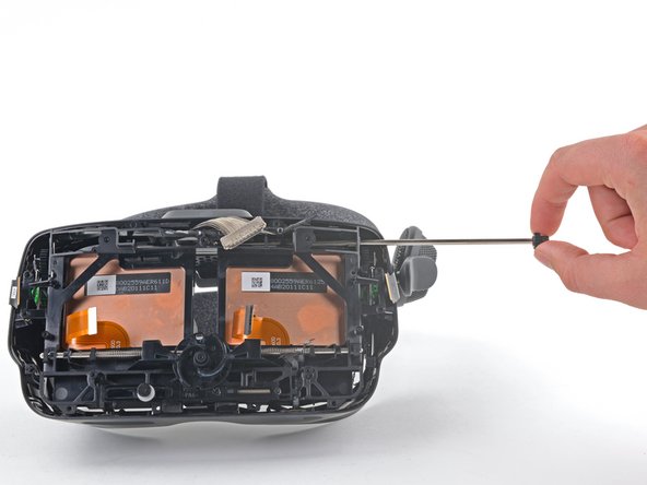
Use a T5 Torx screwdriver to remove the five 6.0 mm screws securing the motherboard to the headset.
-
-
-
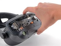
Grab the motherboard by the USB port and carefully remove it from the headset.
-
-
-
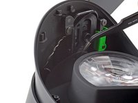
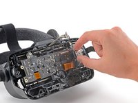
Lift the motherboard shield off of the two cross-shaped alignment pegs.
-
-
crwdns2935267:0crwdne2935267:0Tweezers$4.99
-
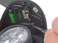
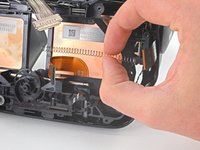
Use your tweezers to remove the rubber boot covering the IPD adjustment screw.
On reassembly, the best method for getting this back on is to get one end on and pulling until it's about half on. Then begin pulling with tweezers and spinning at the same time.
if you're struggling to get this back on, I'd recommend prying at the underside (specifically at the part with the little dent on it) with your flathead screwdriver bit until it splits, then pulling it on and over, using your screwdriver to fold the two halves of the rubber over the screw.
The way I managed to get this back on was to slide the adjuster all the way to one side (eg all the way right) and then put it on starting on the left, then I was able to use the pointy end of a spudger coming in from the front or back of the headset to slide in between the screw head and the rubber piece, into the pocket of the rubber piece (where it folds over) and stretch that part over the sides. The final side I was able to slowly get on just by rubbing the top of the rubber piece in that direction with my fingernail until it went on fully. It definitely took some time.
-
-
-
Use a 2.5 mm (3/32 in) flathead screwdriver to remove the 6.5 mm IPD screw from the headset.
-
-
-
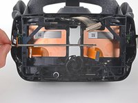
Use a T5 Torx screwdriver to remove the five 4.5 mm screws securing the midframe.
-
-
-
With the midframe loose, slide the case towards the back of the headset to expose the eye tube rails.
-
-
-
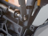
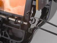
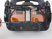
Use a T5 Torx screwdriver to remove the 4.4 mm screw securing the left end gear to the eye tube rail.
-
If the screw is not accessible, turn the eye relief knob to rotate the gear until it faces outward.
-
-
-
Remove the left end gear from the eye tube rail.
-
-
-
Grab the gear on the opposite side and slide the eye tube rail out of the headset.
-
-
-
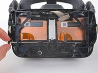
Use a spudger or your fingers to remove three of the four clips from the lower eye tube rail.
-
-
-
Hold each spring with one hand to prevent them from ejecting as you slide the lower eye tube rail out.
-
-
-
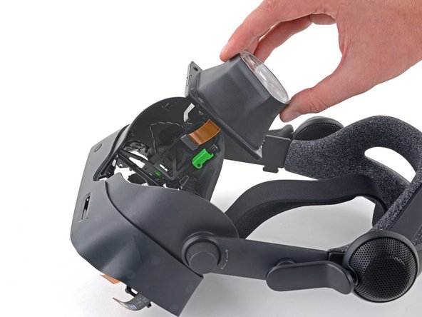
Remove the eye tube(s).
-


Compare your new replacement part to the original part—you may need to transfer remaining components or remove adhesive backings from the new part before installing.
To reassemble your device, follow the above steps in reverse order.
Take your e-waste to an R2 or e-Stewards certified recycler.
Repair didn’t go as planned? Try some basic troubleshooting, or ask our Valve Index Answers community for help.
crwdns2935221:0crwdne2935221:0
crwdns2935229:022crwdne2935229:0
crwdns2947821:0crwdne2947821:0
crwdns2947823:0crwdne2947823:0


crwdns2947412:020crwdne2947412:0
I gained two extra small pieces not mentioned, I think when removing the top rail, they just dropped out into the housing. Looks like they go next to the eye tubes and are not included with the replacement so make sure you don't lose them!
I believe those are suppose to add tension to the top rail. I lost mine but it should be for a small metal spring tensioner (I think).
Gabe -
Great guide. Thanks so much!
Hey, you guys forgot to mention anything about 2small pieces of bent metal no thicker then a staple that looks pretty important. Might want to include every piece that may be affected when assembling/disassembling the headset, Especially in the later stages.
wtf are these??? I also had them fall out and don't know what they are!
I know this is a little bit late, but I'm just going to post this here for anyone doing this in the future: They mention this in step 39. They are EXTREMELY hard to get back in. I recommend putting the headset on it's head and then using your fingers, not tweezers, dropping them in the small upper hole (lower from the index's view). I took a photo of it here.
The metal clip holds the plastic tube in place that the upper rail goes through.
If for some reason you broke the audio connector on step 26, the part number you are looking for is Molex 781710005 and the plug is 781720005.
My IPD adjustment is way out of whack now after a left lens replacement. It's reading much higher numbers than actual and the lowest possible setting reads at 63 or so. Anyone else have their IPD adjustment go off? Any ideas on how to fix it?
For reference I figured this out with help from a comment at the motherboard stage. There is a tiny slider at the top left of the motherboard that fits into a slot on the rear of the RIGHT eye tube (the left eye tube when looking from the motherboard side). When that slide is properly in its slot the digital IPD lines up with the physical IPD correctly. I had missed it when doing a left eye tube replacement because I hadn't focused on the other side.
Jeremy P -
I added a comment on step 21 that shows a picture of this, in case anyone is having the same problem.
For anyone looking, the picture schweinsfuss posted is on slide 21. it's hard to see but the non-rubber component needs to be between the two rubber pieces for it to be correct.
After replacement my windows cannot recognize the headset. In device manager it says "unknown usb device (device descriptor request failed)"
Anyone know how to fix this? I have tried a lot of methods found online, tried replugging, reinstalling...
Is there a way to test which of the eye tubes is faulty?
wear it. see what eye tube is faulty. play a game.
Did it and thanks to this guide the Index is working again.
For everyone searching the web: My symptoms were vertical white lines in my left eye. Got the new eye tube from iFixit and everything is working now!
The Guide needs two updates though.
Step 39 needs to show the black pieces and springs for reassembly as this was very hard. (I think one of the parts is missing in thge pictures of the guide ;-) )
And There seems do be a newer version of the headset that has a plastic plate over the bottom parts of the tubes that prevent them from being extracted. This part is missing in this guide.
BIG THX @samomio for the guide and iFixit for having the part!
I had the same experience with the plastic part. Just bend it down. It just seems to be some kind of dirt-guard. It is quite bendy and doesn't snap or anything. I went pretty rough on it to get the tubes out.
I sold my Index on eBay and somehow during shipment black bits of old foam or something fell out and were visible in the screen so I had to give him a refund. I took the lenses out from the front. I heated them up carefully with a heat gun and used a suction puller and a steel spudger but I slipped and scratched one lens They came out (just one side) seperated. I cleaned all the gunk out and reassembled it. Two years ago - still using it every day. the scratch which is quite clearly visible is not really visible close up strangely enough so it doesnt interrupt my gaming. Now that I have removed a lens I am comfortable that I could easily remove an Index lens. (ratcat17@hotmail.com)
Extremly good guide, took me 2 hours in total. My tip is to print out all the pages, lay them out as you go and put cups or something as containers for the parts on the specific step. There are a huge number of tiny parts in this thing. Makes it way easier to reassemble. Also read step 39 carefully! During reassembly make sure that the upper rail actually goes through the small plastic tube on the eye-tubes, otherwise you won't be able to adjust IPD.
Awesome guide.
Should be mentioned that when turning the headset upside down to remove the eye tubes themself that the gear thing in the middle will fall out, and is a little tedious to get into the right orientation when reassembling.
Also the paperclip-type "springs" are extremely difficult to get back in, would be nice to have more thorough installation instructions on that.
I ended up threading it back through the hole at the bottom, and using tweezers to pull it back up and over the plastic bushings.
Reinstalling the tiny little springs was a nightmare, but I got it done. I found it easiest to turn the headset upside down so that gravity would hold the spring in the right orientation. The rest was patience, dexterity, and a lot of luck...