crwdns2915892:0crwdne2915892:0
This repair guide was authored by the iFixit staff and hasn’t been endorsed by Google. Learn more about our repair guides here.
Follow this guide to remove and replace the charging assembly on a Google Pixel 3 XL.
The charging assembly includes the USB-C port and the SIM card reader.
For your safety, discharge the battery below 25% before disassembling your phone. This reduces the risk of fire if the battery is accidentally damaged during the repair. If your battery is swollen, take appropriate precautions.
Note: The motherboard and loudspeaker can be removed in either order. This guide removes the motherboard before the loudspeaker so there are a few visual discrepancies, but the repair procedure is not affected.
Note: You don't need to remove the rear-facing camera from the motherboard for this repair.
crwdns2942213:0crwdne2942213:0
-
-
Insert a SIM eject tool, bit, or a straightened paper clip into the small hole, located at the bottom edge of the phone.
-
Press firmly to eject the tray.
-
-
-
Remove the SIM tray from the phone.
-
-
-
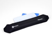
Heat an iOpener and apply it to the right edge of the back cover for a minute.
-
While you wait, note the following areas on the back cover:
-
Strong adhesive—there are large patches of adhesive near the bottom of the phone.
-
Fingerprint sensor cable—be careful not to slice through the cable as you pry
-
-
-
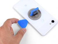
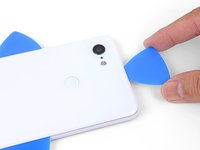
Apply a suction cup to the heated edge of the back cover, as close to the edge as possible.
-
Pull up on the suction cup with strong, steady force to create a gap.
-
Depending on the age of your phone, this may be difficult. If you are having trouble, apply heat to the edge and try again.
-
Insert the point of an opening pick into the gap.
Suction cup doesn’t work on severely cracked glass.
Step 1 - 2 took me about 50 minutes. Back and forth with heat and trying with suction cup. I could get my finger nail in but not the pick. Took two people, but we finally got a pick in. 2 year old phone.
Took about 15 minutes and three total attempts. On the third attempt, I also used a thinner, metal, pick to widen the gap just enough for the plastic pick to fit (Though be careful as you can easily break it with a metal pick). The phone is three years old.
Could not get in with the pick or in from the side. Targeted the bottom of the phone with the iOpener and managed to gently create some space for the pick with the opener tool.
I also struggled here for a while. I ended up working my way around the entire edge of the phone until I found one spot where I could pry up the back panel. I used a jimmy instead of the opening pics. I also used a hairdryer on lower heat instead of the iopener. 3 year old phone.
Took 30 minutes + to get the back cover off. Used another suction cup to grip from the busted screen and the ifixit suction cup for the back. A thinner Acoustic guitar pick was required opposed to the standard Blues picks provided in the kit (har-har). Would HIGHLY suggest getting a pick into both the back and the front before removing the panels as it will give you more surfaces to pry from. Made that mistake...
Over 2 hours of trying, I keep reheating the pouch and let it sit on the edge for sometimes up to 10 minutes since the directed 1 minute wasn't working. Physically cant get enough leverage on the back of the phone; picks are too thick to get under the crack, and the suction cup pops off before I can get enough force to see any gap open. Phone is 5 years old. I really need some help
Hey Grant!
I hear your pain—the adhesives on this phone are very strong. The initial gap is one of the hardest parts of the procedure. Here are some suggestions:
* If you have a hair dryer, give that a shot. Heat the edge until it is slightly too hot to the touch.* These adhesives separate not with extreme force, but with constant steady force and time. Try heating the edge and pull on the suction cup with firm force for about a minute to let the adhesive separate.
* If you have an opening tool, you can try this procedure to get the initial gap.
Need a guide for if the back glass is broken!
-
-
-
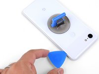
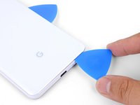
Slide the opening pick along the right edge to slice through the adhesive.
-
The adhesive gums up and becomes hard to slice once it cools. If that happens, re-apply heat to the edge to make slicing easier.
-
Once you have sliced through the edge, leave an opening pick in the seam to prevent the adhesive from re-sealing.
-
-
-
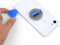
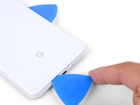
Apply a heated iOpener to the bottom of the back cover for a minute.
-
-
-
Use an opening pick to slice around the bottom right corner and continue along the bottom edge of the phone.
-
Leave a pick in the edge to prevent the adhesive from re-sealing.
-
-
-
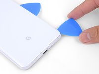
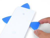
Continue heating and slicing the remaining edges of the phone.
-
Be careful as you slice along the left edge of the phone. If your pick feels like it's stuck near the top, you may have snagged the fingerprint sensor. Retract the pick out of the seam slightly and try again.
-
Be sure to cut through the thick portions of adhesive near the bottom and right edge of the phone.
The back cover is Glass!!!!. DO NOT PRY HARD, IT WILL BREAK!!!!!!!
You must go slowly and let the heat do the work, if you force the cover off, it will shatter.
-
-
-
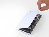
Gently pry up the right edge of the back cover.
-
Use an opening pick to slice through any remaining adhesive along the edges.
-
-
-
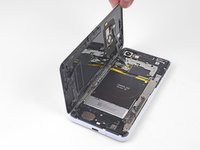
Swing the right edge of the back cover upwards and rest the flipped panel along the left side of the phone.
Reassembly is way harder. The adhesive guide is generic and not super helpful, so don't be surprised if things went smoothly until you get to this step and then everything starts sticking to things its not supposed to.
This is great but how you address that fact that the phone is tied to a particular fingerprint sensor and after replacing, the new sensor is not recognized by the original phone?
Hi Dave!
There's a software calibration tool that you can use to calibrate your new fingerprint sensor. I've updated this step to include a link to the tool.
I have a pixel 3 xl and I can't get the tool to work. I finally got the driver's installed after several hours and it says it's for pixel 6 and up basically. So I tried the other option and it's basically saying to do a factory reset? Did I mess something up on the install or what am I doing wrong here? Thanks
Uhhh
So, apparently the connector on the motherboard for the fingerprint sensor is just ridiculously fragile, because after plugging and screwing everything in (pretty much reassembled except for the adhesive), I closed up the phone and powered it on to test if everything was working, and when I opened it back up and let the top hang off to the side, it just snapped off. I didn't even have it tensioned that much, it was just hanging off to the side and snapped. So now I've traded a non-functional camera with a non-functional and irreparable (unless I get a new motherboard) fingerprint sensor.
The guide really ought to emphasize how delicate that connector really is. I have a google drive link here to a photo of the remnants of my poor fingerprint sensor connector :( link
Wasted a ton of time and effort (and money) trying to use this guide to repair my Pixel 3XL. Then I get to the software calibration tool and find:
Unsupported deviceThis is not a compatible device. Only Pixel 6, 6 Pro, 6a, 7, 7 Pro, 7a devices can install this software.
I cannot say how frustrating it is when a guide and website that tried to be so helpful ends up like this. Failure due to referencing tools not on the site and not suitable for the job.I too want to stress just how sensitive the fingerprint sensor cable is. Be sure you are only lifting the back away a very small amount until you are able to disconnect the cable. I thought I was being careful and ended up still putting a small tear in the cable!
The good news is that a replacement sensor is well under $10 shipped. Also, I'm not sure why this guide recommends the use of the software tool.
It is not compatible with the 3XL (and I'm not sure it ever was). I had some reservations when I read this when I had to replace my sensor, but I found comments else where stating that nothing was needed. Sure enough, when I got my new sensor installed, it worked with no issues. I didn't need to calibrate, or reset my device. I just needed to set my fingerprints up again.
-
-
crwdns2935267:0crwdne2935267:0Tweezers$4.99
-
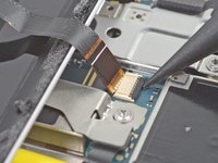
User tweezers to carefully peel up the yellow tape over the fingerprint sensor connector.
This step is utterly unnecessary. It achieves nothing, and the tape is there for a reason (I'm not sure why, maybe to prevent short circuits). I didn't remove this tape while disassembling and it didn't change anything.
The Kapton tape should adhere to both the cable and the connector. It helps prevent the cable from slipping out of the ZIF connector. You're right in that you don't have to completely remove the tape—I've adjusted the step to reflect this.
I just finished this guide, thank you. It would be nice to have a "before ribbon removed" reference picture that's also without the Kapton tape in place if possible. I was no longer certain how far back into the ZIF connector I had to place the ribbon cable as I simply forgot what it looked like before removing it. Basically, it "felt" like it was out too far, but since I had no reference I couldn't compare. Step 10 has good close up pics, but the ribbon cable is already out a bit so a bad reference.
-
-
-
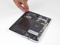
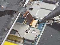
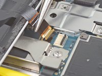
Use the point of a spudger to carefully flip up the black lock bar on the fingerprint sensor's ZIF socket.
-
Grasp the cable's tab with your fingers or tweezers and gently walk the flex cable out of the socket.
-
-
-
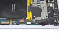
Remove the back cover.
-
-
crwdns2935267:0crwdne2935267:0Magnetic Project Mat$17.96
-
Remove the following four T3 screws securing the metal cover bracket:
-
Three 4 mm long screws
-
One 3 mm long screw
Be careful when putting the screws back in that you do not over tighten. This will cause you to destroy some pixels on your screen.
The long screw on my disassembly was adjacent to the lettering for the Qi inductive receiver, and not close to the silver exposed part of the battery as indicated
In my case, all the screws are the same length.
-
-
-
Insert the flat end of a spudger underneath the top right edge of the metal bracket and pry up to loosen it.
-
Remove the metal cover bracket.
There is a small adhesive pad under the metal bracket, between the two middle screws that will provide some resistance when lifting the metal cover bracket
-
-
-
Use the point of a spudger to pry up and disconnect the battery connector from its socket.
-
Bend the battery cable such that the connector will not accidentally touch the socket.
-
-
-
Remove the five T3 screws securing the motherboard shield:
-
Three 4 mm long screws
-
Two 3 mm long screws
-
-
-
-
Remove the motherboard shield.
-
-
-
Remove the three 3 mm long T3 screws securing the front camera bracket.
-
-
-
Remove the front camera bracket.
-
-
-
Use the point of a spudger to carefully pry up and disconnect the cameras from their motherboard sockets.
-
-
-
Use the flat end of a spudger to pry up and loosen the camera modules from their recess.
-
-
-
Remove the front-facing cameras.
-
-
-
Remove the 4 mm long T3 screw securing the top-right corner of the loudspeaker.
-
-
-
Remove the two 3 mm long T3 screws securing the button array connector bracket.
-
-
-
Remove the button array connector bracket.
-
-
-
Use the point of a spudger to pry up and disconnect the earpiece connector from its motherboard socket.
-
Carefully remove the connector pad surrounding the earpiece socket.
-
-
-
Use the point of a spudger to pry up and disconnect the following:
-
Microphone connector
-
Button array connector
-
Earpiece connector (should already be disconnected)
-
-
-
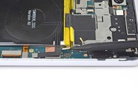
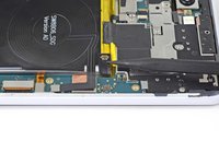
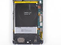
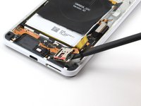
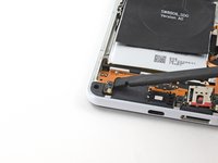
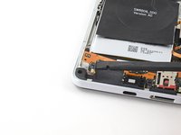
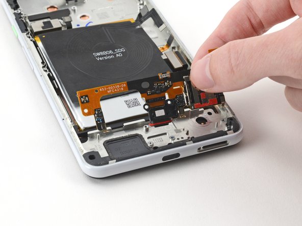
Use the point of a spudger to pry up and disconnect the following:
-
Charging coil connector
-
Left squeeze sensor connector
-
Display connector
-
Right squeeze sensor connector
-
Loudspeaker connector
-
USB-C port connector
-
-
-
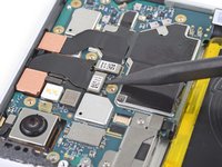
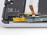
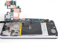
Remove the two 3 mm long T3 screws securing the motherboard.
-
-
-
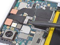
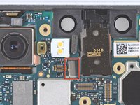
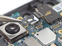
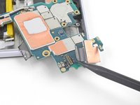
Insert the point of a spudger underneath the motherboard, near the rear-facing camera module.
-
Pry up gently to loosen the motherboard from its recess.
-
If the motherboard is not budging, make sure you have disconnected all the connectors.
-
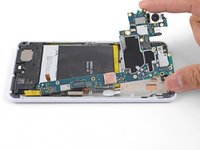
The motherboard has to squeeze past the earpiece speaker cable. If too much pressure is put on the earpiece cable, the earpiece speaker will pop open. You can prevent this by pressing on the earpiece module with a finger while you maneuver the motherboard out.
-
-
-
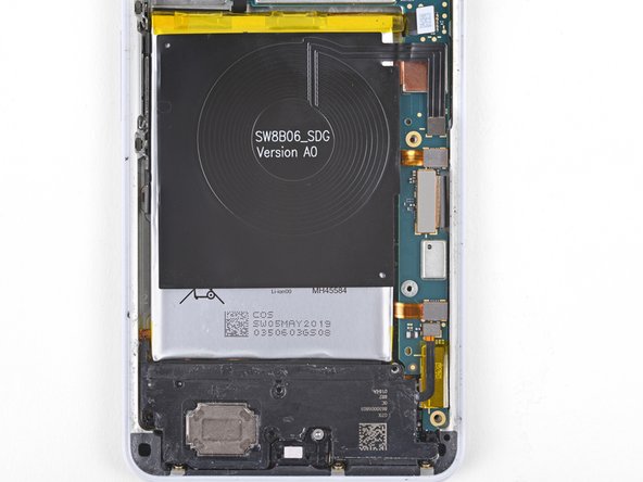
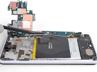
While you perform this step, take care to keep slack on the antenna cables attached to the bottom leg of the motherboard.
-
Lift the top half of the motherboard slightly to clear the board from its recess.
-
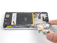
Twist the left edge of the board over and out of the phone and rest the board on the right edge of the phone.
-
-
-
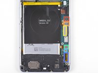
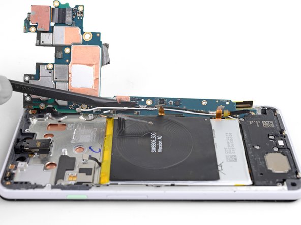
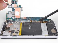
Use the flat of a spudger to gently pry up and loosen the black and white antenna cables from their motherboard clips.
-
-
-
Remove the motherboard.
-
-
-
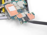
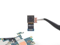
Use the point of a spudger to pry up and disconnect the rear-facing camera from its motherboard socket.
-
Remove the rear-facing camera and transfer it to your replacement motherboard.
-
-
-
Remove the following four T3 screws securing the loudspeaker:
-
Three 4 mm long screws
-
One 3.9 mm long screw
-
-
-
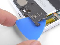
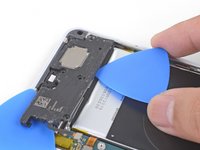
Insert the point of an opening pick under the bottom right corner of the loudspeaker.
-
Slide the pick in to loosen the right side of the loudspeaker.
-
-
-
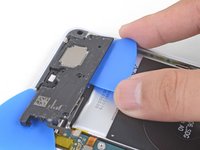
Insert the point of an opening pick under the top edge of the loudspeaker, below the battery.
-
Slide the opening pick in to slice through the adhesive gasket under the loudspeaker.
-
-
-
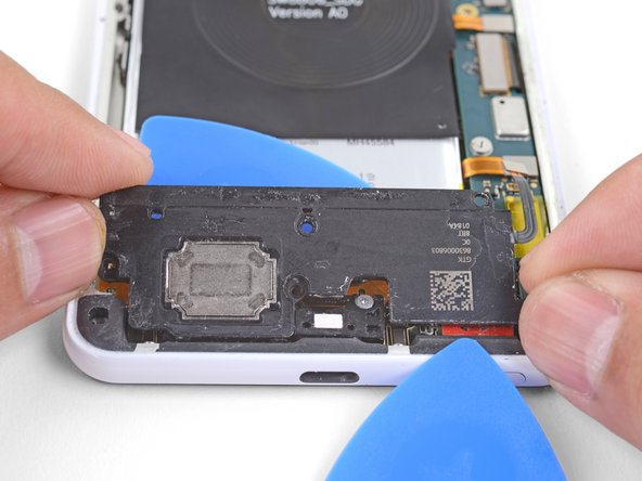
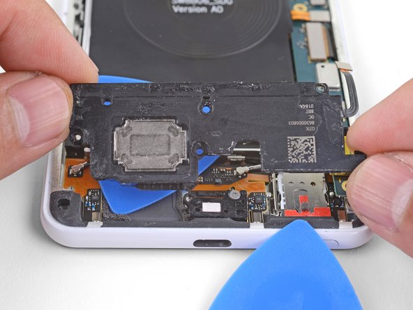
Lift the loudspeaker out slowly and pull it away from any remaining adhesive.
-
Remove the loudspeaker.
-
-
-
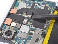
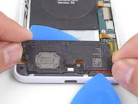
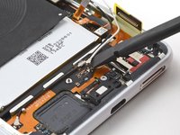
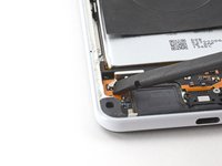
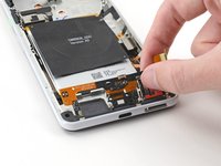
Use the flat end of a spudger to pry up and disconnect the white coaxial cable connector from the charging assembly.
-
-
-
Remove the white coaxial cable from the phone.
-
-
-
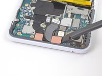
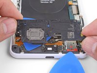
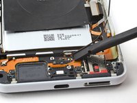
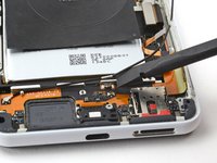
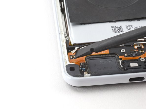
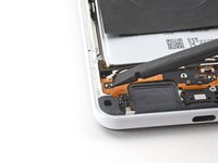
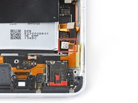
Use the flat end of a spudger to pry up and detach the black coaxial cable from its clip on the charging assembly.
-
-
-
Use the flat end of a spudger to pry up and disconnect the black coaxial cable connector from the charging assembly.
-
-
-
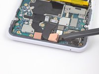
Remove the black coaxial cable from the phone.
-
-
-
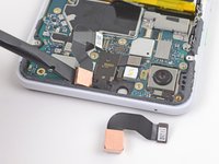
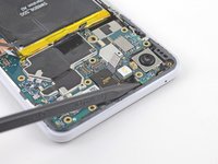
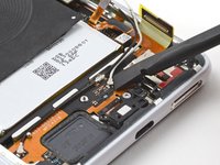
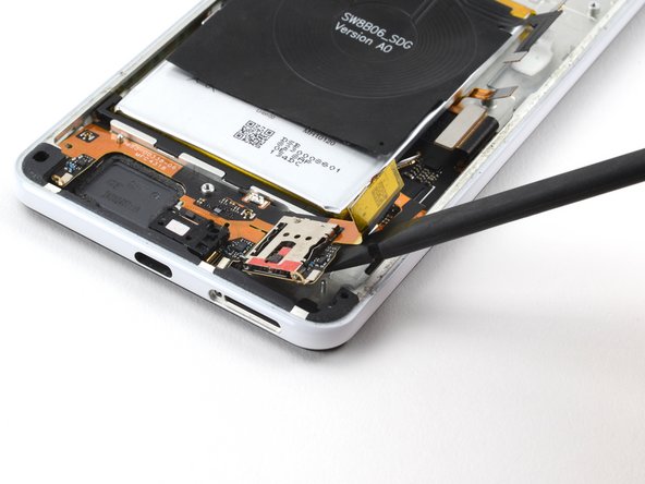
Use a T3 Torx screwdriver to remove the three 2.4 mm screws securing the charging assembly to the frame.
-
-
-
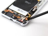
Use a T3 Torx screwdriver to remove the 3.9 mm screw securing the USB-C port bracket to the frame.
-
-
-
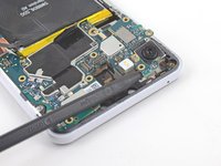
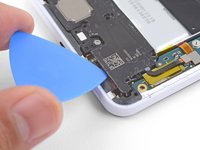
Slide the flat end of a spudger under the right side of the charging assembly to detach it from the frame.
-
-
-
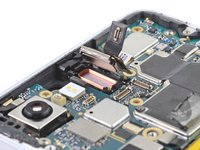
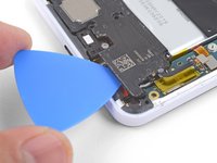
Insert the flat end of a spudger under the left side of the charging assembly.
-
Pry up and detach the left side of the charging assembly from the frame.
-
-
-
Remove the charging assembly from the frame.
-
The right squeeze sensor cable is adjacent to the bottom right corner of the battery.
-


Compare your new replacement part to the original part—you may need to transfer remaining components or remove adhesive backings from the new part before installing.
To reassemble your device, follow these instructions in reverse order.
Take your e-waste to an R2 or e-Stewards certified recycler.
Repair didn’t go as planned? Try some basic troubleshooting, or ask our Google Pixel 3 XL Answers community for help.
crwdns2935221:0crwdne2935221:0
crwdns2935227:0crwdne2935227:0

crwdns2947412:02crwdne2947412:0
I have seen several listings that Charging assembly has Microphone?! Is that true?
Tips for this repair:
- Remove the loudspeaker before removing the motherboard, it makes it much easiert to remove.
- It's unneccessary to remove the antenna cable from the mainboard, only remove it from the charger board.
Applying the adhesive was the hardest part.
Scraping off the old adhesive did not put me into a good mood either.
Kiki - crwdns2934203:0crwdne2934203:0