crwdns2915892:0crwdne2915892:0
Follow this guide to replace the motherboard in your Sony DualSense controller. Replacing the motherboard is necessary to resolve joystick drift and charging port failure. Make sure to purchase a motherboard that includes joysticks calibrated at the factory.
Note: This guide is for current DualSense controllers with FCC IDs that end with A. Check the back of your controller to verify your model. If yours ends in a 1, it is an early model and there will be internal differences. Follow these guides for the earlier version.
crwdns2942213:0crwdne2942213:0
-
-
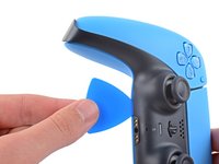
Insert an opening pick underneath the middle trim at the bottom-right corner of the controller to release the clips securing it to the case.
-
-
-
Slide the opening pick along the lower-right edge of the middle trim to release the clips securing it to the case.
-
-
-
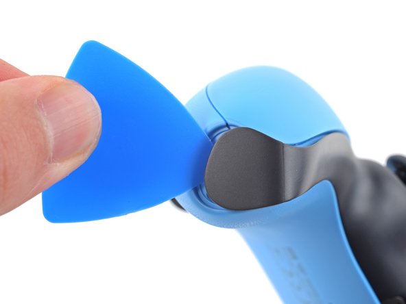
Insert an opening pick underneath the middle trim at the bottom-left corner of the controller to release the clips securing it to the case.
-
-
-
Slide the opening pick along the lower-left edge of the middle trim to release the clips securing it to the case.
-
-
-
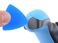
Use your fingers to lift up the bottom edge of the middle trim to release the remaining clips.
-
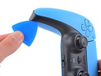
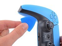
Lift the middle trim over the joysticks to remove it.
-
-
-
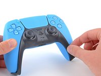
Insert the flat end of your spudger into the gap above the L1 button.
-
Pry the spudger upward to remove the L1 button.
-
-
-
Insert the flat end of your spudger into the gap above the R1 button.
-
Pry the spudger upward to remove the R1 button.
-
-
-
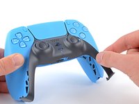
Use a Phillips screwdriver to remove the two 6.5 mm screws securing the bottom corners of the lower case.
-
-
-
Use a Phillips screwdriver to remove the two 6.5 mm screws behind the L1 and R1 buttons.
-
-
-
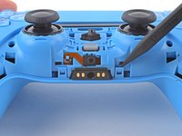
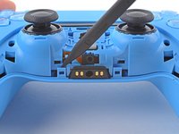
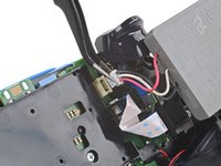
Use the pointed edge of a spudger to unclip the two clips on either side of the headset jack.
-
-
-
-
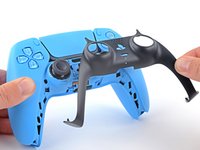
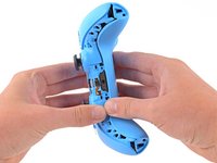
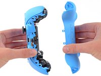
Use your hands to carefully pull the rear case off of the controller.
You can´t just grab both ends and expect it to open flawlessly, first you gotta travel the spudger around the seam at the outer edges of the controller, there are multiples clips in that area, there a couple really hard to get out at the outer edges of the R1 and L1 buttons, for those you need to insert the spudger bending outwards the bottom piece of the controller (a fairly amount, like 1.5mm) and while bending outwards use the same inserted spudger to lever them apart carefully, the plastic will bend quite a bit so be very careful with the motion of the spudger.
Yet again, that was my personal experience opening it up, try first as the guide says, if you feel the upper and bottom pieces glued around the R1 and L1, then try this.I had the same experience, the best way to reach these for me was to place the spunger from L1 R1 side whilst using a spunger to press outwards from the side like in Carlos's comment. Thank you Carlos I was struggling with this!
This did not work for me. Finally I just pulled the two parts apart at the bottom side, carefully twisting and manipulating until the parts clicked loose at the top side
This is the biggest hassle in the whole process. It seems that all controllers now come with those extra clips that other people mentioned here. I, however, didn't have the same success with their steps of running a spudger on the sides to undo the clip. Looking around, I found this Youtube video showing that you can undo the clips simply by twisting up from the bottom. Do it carefully because it pops off easily using this method - when I did, I used some force and the back just flew from my table.
I found it easier like that and was able to continue the process.
+1 to this. None of the suggestions worked well enough for me, but this video clip got this step done for me nearly instantly. note the position of the tech's fingers and thumbs - I copied that exactly and had no issue.
Nathan K -
-
-
-
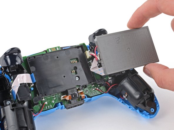
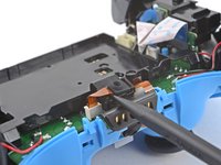
Lift the battery out of its bracket and reposition it to the right for better access to the battery connector.
-
-
crwdns2935267:0crwdne2935267:0Tweezers$4.99
-
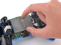
Use a pair of tweezers or your fingers to disconnect the battery from the motherboard.
-
-
-
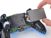
Remove the battery.
-
-
-
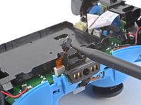
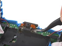
Use the pointed end of your spudger to remove the lower microphone from its bracket next to the battery.
-
-
crwdns2935267:0crwdne2935267:0Tweezers$4.99
-
Grab the lower microphone ribbon cable pull tab with your fingers or a pair of tweezers and disconnect it from the motherboard.
-
-
-
Use a Phillips screwdriver to remove the 6.5 mm screw securing the battery bracket.
-
-
-
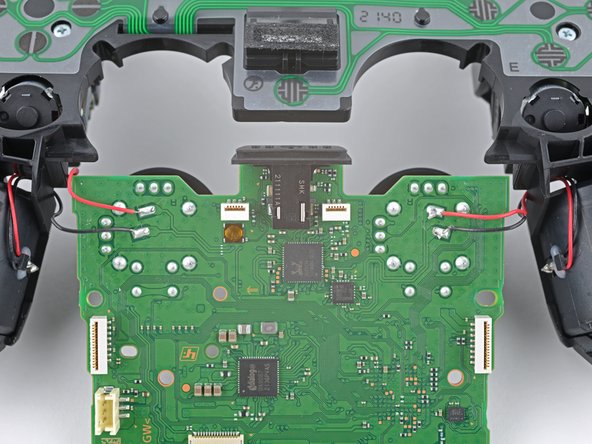
Lift the battery bracket off of the motherboard.
The bottom left and right tabs of the battery bracket are meant to protect and retain the motor wires. In this guide step, you can see the wires are wound around the bracket. Move the wires behind this bracket and you won't have to worry about pinching the wires while reassembling the rear case.
-
-
-
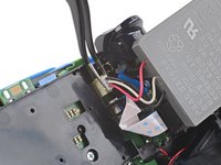
Grip the right trigger assembly cable with a pair of tweezers or your fingers and disconnect it from the motherboard.
-
Don't completely remove the ribbon cable yet.
I think the cable you see here is put in backwards. The "Double Line" pull tab should connect to the motherboard.
TRADUCCION:
Creo que el cable que se ve aquí está puesto al revés. La lengüeta de tiro "Doble línea" debe conectarse a la placa base.
Carlos López (España - Spain) - crwdns2934203:0crwdne2934203:0
-
-
-
Grip the right trigger assembly cable with a pair of tweezers or your fingers, and disconnect it from the trigger assembly.
-
-
-
Grip the left trigger assembly cable with a pair of tweezers or your fingers to disconnect it from the motherboard.
-
Don't completely remove the ribbon cable yet.
-
-
-
Grip the left trigger assembly cable with a pair of tweezers or your fingers to disconnect it from the trigger assembly.
-
-
-
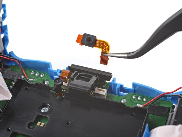
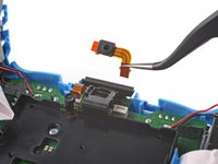
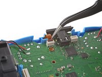
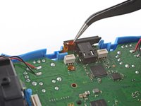
Use a pair of tweezers or your fingers to disconnect the upper microphone from the motherboard.
per sbaglio ho tirato forte la linguetta arancione in basso a destra e non so più dove inserirla
-
-
-
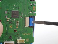
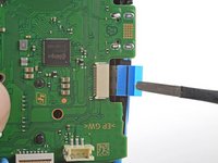
Use a pair of tweezers or your fingers to disconnect the touchpad cable from the motherboard.
-
-
-
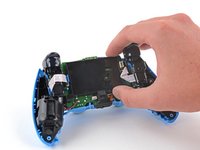
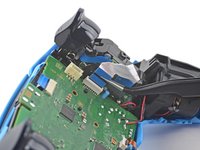
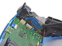
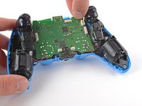
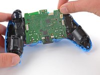
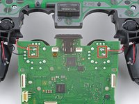
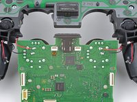
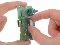
Carefully guide the joysticks through the front case and lift the motherboard out.
There's small tabs holding the board in place along the side.
-
-
-
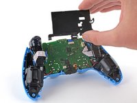
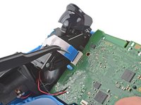
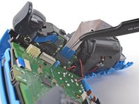
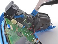
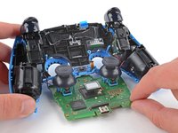
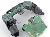
Flip the motherboard and midframe over to access the red and black vibration motor wires.
-
Use a soldering iron to disconnect the vibration motor wires from the motherboard.
-
-
-
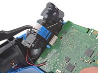
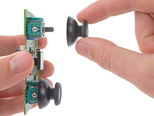
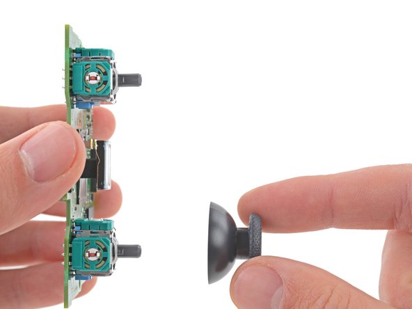
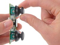
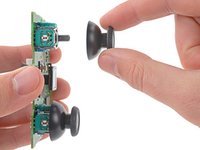
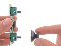
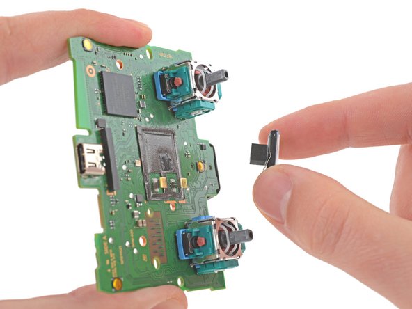
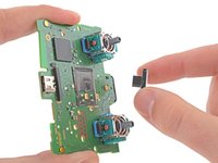
Use your fingers to remove the left and right joystick covers from the motherboard.
-
-
-
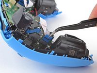
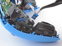
Use your fingers to remove the speaker and foam pad from the motherboard.
-


To reassemble your device, follow these instructions in reverse order.
Take your e-waste to an R2 or e-Stewards certified recycler.
Repair didn’t go as planned? Try some basic troubleshooting, or ask our Answers community for help.
To reassemble your device, follow these instructions in reverse order.
Take your e-waste to an R2 or e-Stewards certified recycler.
Repair didn’t go as planned? Try some basic troubleshooting, or ask our Answers community for help.
crwdns2935221:0crwdne2935221:0
crwdns2935229:04crwdne2935229:0

crwdns2947410:01crwdne2947410:0
"Replacing the motherboard is necessary to resolve joystick drift and charging port failure." Cleaning the joysticks out with compressed air and/or rubbing alcohol can often resolve the drift issue until it needs to be cleaned again. Joystick replacement is an option without total board replacement. Controllers possibly to calibrate at startup and can be reset to calibrate as well https://osgamers.com/frequently-asked-qu...
Charge port failure definitely doesn't require a board replacement. It's the pins are small, but should be manageable with flux.