crwdns2935425:06crwdne2935425:0


-
There are 2 ventilated metal covers here, held down by 7 screws total. The IO PCB does not have to come out, but makes it a little easier to reach the screws.
-
4 screws in the color wheel /light path cover (at the top in the photo), and 3 in the lamp house cover (at bottom in photo).
-
If you choose to remove the IO PCB entirely, these 5 standoffs are where the PCB screws go.
-
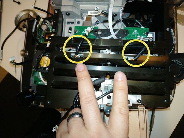
As you lift off the lamphouse cover, carefully work around these two wires -- for the lamp hour chip readers. They connect to boards below the cover -- it's probably better to leave them connected to the IO PCB, and unplug the connectors circled here instead.
-
The color wheel bracket is held down by just 3 T10 screws -- but they're about 14mm long and tricky -- especially the middle one, where you must reach through a hole in this black plastic gusset. I suggest using screwdriver with a magnetic tip here.
-
Once these 3 screws are removed, the color wheel bracket will be wobbly and loose. Lift it up carefully -- the wheels are very thin optical glass.
crwdns2944171:0crwdnd2944171:0crwdnd2944171:0crwdnd2944171:0crwdne2944171:0