crwdns2935425:05crwdne2935425:0


-
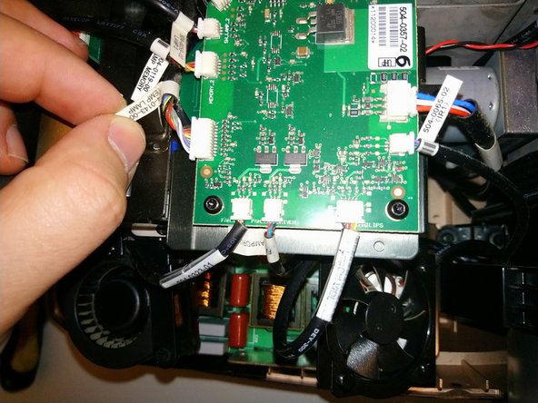
To reach the color wheels, we must remove the lamphouse cover. This PCB doesn't actually have to be removed, but all the wires going to it must be disconnected.
-
PD was very considerate in manufacturing these projectors -- there are labels on the cable and on the PCB connector.
-
Starting at the large ZIF ribbon cable, and naming them clockwise, we have: IO card ribbon cable, DC POWER IO, Fan Main, IR, Fan Ctrl VDI, Fan Lamp Driver, [lamp blower fan], Temp Lamp, Lamp Memory, Lamp 2 (switch), CW2, color wheel 2 ribbon, color wheel 1 ribbon, CW1, Lamp 1, Lamp Memory, Temp Out, [lamp 1 blower fan], Fan Lamp Driver, LMP Ctrl VDI, IR2
-
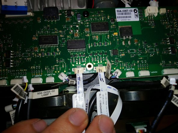
Well, most of my cables were well-labeled. Some, though, are close together enough and similar enough to possibly be confused. So, I suggest labeling connector and cable with marker to distinguish them. See example in pic 3 -- these are ribbon cables for the color wheel motors, and the 3-wire connectors for the position sensors.
crwdns2944171:0crwdnd2944171:0crwdnd2944171:0crwdnd2944171:0crwdne2944171:0