crwdns2933423:0crwdne2933423:0

Teufel Rockster electronics repair

crwdns2936319:0crwdne2936319:0
crwdns2936315:0crwdne2936315:0
crwdns2931653:03crwdne2931653:0
Teufel Rockster Elektronik Reparatur, Schritt 2 (Option 1) überprüfen: crwdns2935265:00crwdnd2935265:01crwdnd2935265:03crwdne2935265:0 Teufel Rockster Elektronik Reparatur, Schritt 2 (Option 1) überprüfen: crwdns2935265:00crwdnd2935265:02crwdnd2935265:03crwdne2935265:0 Teufel Rockster Elektronik Reparatur, Schritt 2 (Option 1) überprüfen: crwdns2935265:00crwdnd2935265:03crwdnd2935265:03crwdne2935265:0
Schritt 2 (Option 1) überprüfen
  • Das Netzteil kann / sollte nach der Reparatur mit Last überprüft werden.

  • Die Versorgung (12V) an "Ext. Bat" und GND anschließen.

  • Freigabesignal mit 3,3V an Pin 5 (gelb) anschließen. Bei "Int. Bat" wäre das Pin 4

  • Am Ausgang (Krokoklemme grün und gelb) sollten nun 25V im Leerlauf anliegen. Bei Belastung des Ausgangs mit einem 10 Ohm Widerstand sollte die Leitungsaufnahme ~100 Watt betragen.

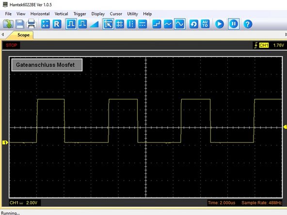
  • Bei Belastetem Ausgang sieht die Ansteuerung der MOSFET Gates wie in dem Oszibild aus

  • Bevor ich aber soweit gekommen bin, mussten in meinem Fall noch folgende Bauteile ersetzt werden: Der PWM Generator Tps40090, ein Gate Treiber UCC27324 und ein Feedback Widerstand 2R29 mit 200 Ohm

Follow this step to test the power supply after a repair (as described in step 2 / option 1)

Connect an external 12V power supply to the board's power terminals.

Supply 3.3V to pin 5 of the header.

At the output (green and yellow crocodile clips), there should now be 25V in no-load mode. If the output is loaded with a 10 Ohm resistor, the power consumption should be ~100 watts.

When the output is loaded, probing the MOSFET control pin with an oscilloscope should look like the third image.

But before I got that far, I had to replace the following components: The PWM generator Tps40090, a gate driver UCC27324 and a feedback resistor 2R29 with 200 ohms

crwdns2944171:0crwdnd2944171:0crwdnd2944171:0crwdnd2944171:0crwdne2944171:0