crwdns2915892:0crwdne2915892:0
Follow the steps in this guide to replace the power button cable assembly in your iPhone 6s Plus.
crwdns2942213:0crwdne2942213:0
-
-
Power off your iPhone before beginning disassembly.
-
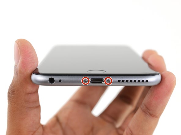
Remove the two 3.4 mm Pentalobe screws on either side of the Lightning port.
-
-
crwdns2935267:0crwdne2935267:0Clampy - Anti-Clamp$24.95
-
Pull the blue handle backwards to unlock the Anti-Clamp's arms.
-
Slide the arms over either the left or right edge of your iPhone.
-
Position the suction cups near the bottom edge of the iPhone just above the home button—one on the front, and one on the back.
-
Squeeze the cups together to apply suction to the desired area.
-
-
-
Pull the blue handle forwards to lock the arms.
-
Turn the handle clockwise 360 degrees or until the cups start to stretch.
-
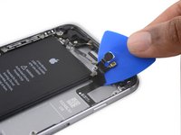
Insert an opening pick under the screen when the Anti-Clamp creates a large enough gap.
-
Skip the next three steps.
-
-
crwdns2935267:0crwdne2935267:0Clampy - Anti-Clamp$24.95
-
If you don't have an Anti-Clamp, follow the next three steps to use a suction handle.
-
Apply mild heat to the lower edge of the iPhone using an iOpener or hair dryer for about a minute.
-
-
-
Apply a suction cup to the lower left corner of the display assembly.
-
-
-
Pull up on the suction cup with firm, constant pressure to create a slight gap between the front panel and rear case.
-
-
-
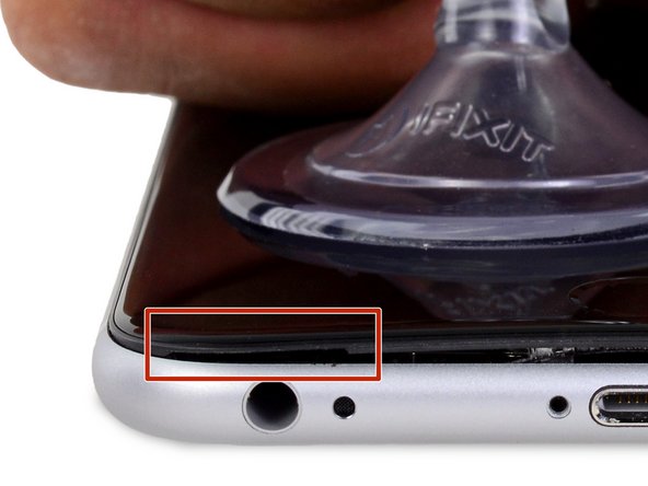
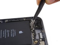
The safest place to pry from is the notch in the front panel above the headphone jack.
-
While still maintaining pressure on the suction cup, insert the flat tip of a spudger into the gap, directly above the headphone jack.
-
-
-
Twist the spudger to widen the gap between the front panel and the rear case.
-
-
-
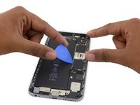
While firmly pulling up on the suction cup, slide the edge of the spudger under the bottom left corner of the display.
-
-
-
Slide the tip of the spudger up the left side of the phone, between the front panel and the rear case.
-
-
-
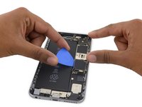
Insert the flat tip of the spudger under the right edge of the display.
-
Slide the spudger up the right side.
-
-
-
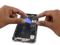
Use a plastic opening tool to hold down the rear case while pulling up the suction cup to open the phone.
-
-
-
Pull up on the small nub on the suction cup to remove it from the display.
-
-
-
Gently grasp the display assembly and lift it up to open the phone, using the clips at the top of the front panel as a hinge.
-
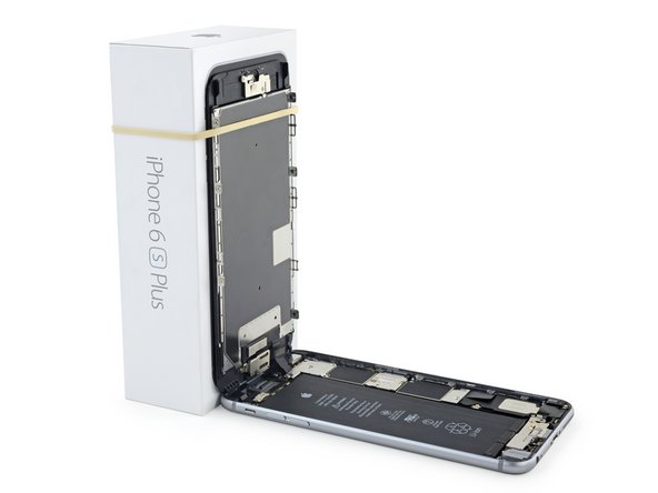
Open the display to about a 90º angle, and lean it against something to keep it propped up while you're working on the phone.
-
Add a rubber band to keep the display securely in place while you work. This prevents undue strain on the display cables.
-
-
crwdns2935267:0crwdne2935267:0Magnetic Project Mat$19.95
-
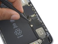
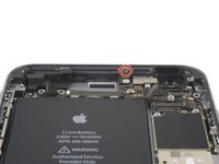
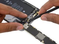
Remove two Phillips screws securing the battery connector bracket to the logic board, of the following lengths:
-
One 2.9 mm screw
-
One 2.3 mm screw
-
-
-
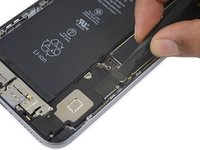
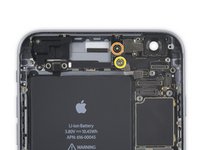
Remove the battery connector bracket.
-
-
-
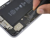
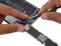
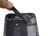
Use a spudger or a clean fingernail to disconnect the battery connector by prying it straight up off the logic board.
-
-
-
Bend the connector back to ensure it doesn't make contact and power the iPhone on while you're working on it.
-
-
-
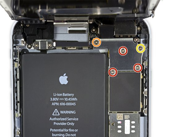
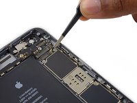
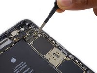
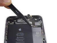
Remove the following Phillips screws:
-
Three 1.3 mm screws
-
One 1.6 mm screw
-
One 3.0 mm screw
-
-
-
-
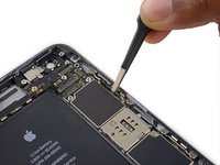
Use a plastic opening tool to disconnect the front-facing camera and sensor cable connector.
-
-
-
Use a plastic opening tool to disconnect the digitizer cable by prying it straight up from its socket on the logic board.
-
-
-
Disconnect the home button/fingerprint sensor cable by prying it straight up from its socket on the logic board.
-
-
-
Peel up any tape covering the iSight camera bracket screws.
-
-
-
Remove the following Phillips screws over the camera bracket:
-
One 1.9 mm screw
-
One 2.4 mm screw
-
-
-
Disconnect the iSight camera connector from its socket on the logic board.
-
-
-
Insert the flat end of the spudger between the iSight camera and rear casing.
-
Gently pry the camera out from its housing.
-
-
-
Insert a SIM eject tool into the hole in the SIM tray.
-
Press to eject the SIM tray.
-
-
-
Remove the single 1.4 mm Phillips screw holding the NFC bracket in place.
-
-
-
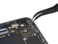
Remove the two 2.7 mm Phillips screws securing the audio control cable bracket to the logic board.
-
-
-
Remove the audio control cable bracket.
-
-
-
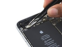
Disconnect the audio control cable by prying its connector straight up from its socket on the logic board.
-
-
-
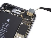
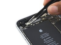
Disconnect the cellular antenna cable by prying its connector straight up from its respective socket on the logic board.
-
-
-
Disconnect the Wi-Fi diversity antenna cable by prying its connector up from the logic board.
-
-
-
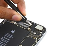
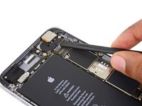
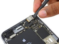
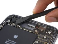
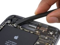
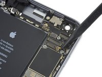
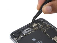
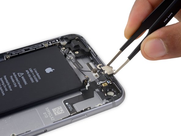
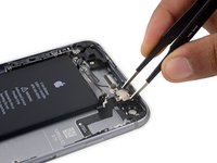
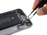
Disconnect the power button flex cable from its socket on the logic board.
-
-
-
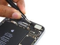
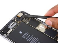
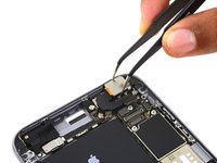
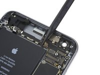
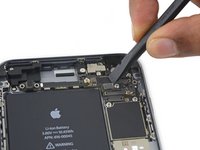
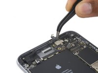
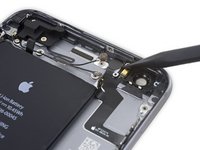
Disconnect the antenna cable by prying it up from the logic board.
-
-
-
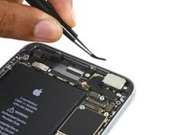
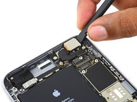
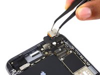
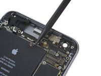
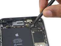
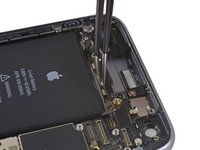
Use the flat end of a spudger to disconnect the Lightning connector flex cable from the logic board.
-
-
-
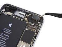
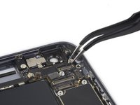
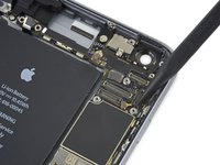
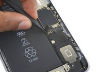
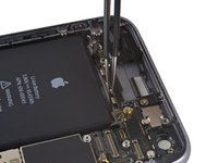
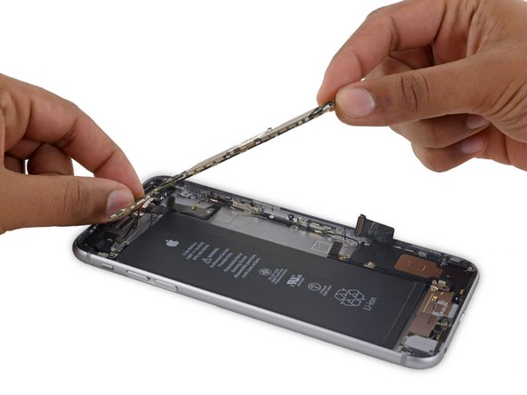
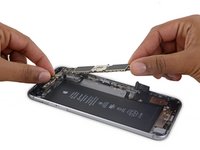
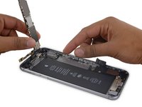
Deroute the antenna cable from the two clips on the right edge of the logic board.
-
-
crwdns2935267:0crwdne2935267:0Standoff Screwdriver for iPhones$5.49
-
Remove the following screws:
-
One 1.3 mm Phillips screw
-
One 2.6 mm Phillips screw
-
One 2.2 mm standoff screw
-
-
-
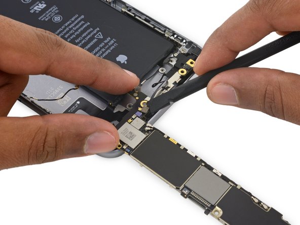
Deroute the upper left cellular antenna cable from the first logic board clip by nudging it out from under the clip, towards the battery.
-
-
-
Continue derouting the cellular antenna cable from the second and third logic board clips.
-
Use the pointed tip of a spudger to gently pry the cellular antenna cable from the middle logic board clip.
-
-
-
Remove the final 2.0 mm Phillips screw directly below the SIM card reader.
-
-
-
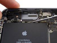
Carefully raise—but do not remove—the logic board, lifting it from the bottom edge nearest the Lightning connector.
-
-
-
Tip the logic board up to a vertical position to expose the single antenna connector on the underside, near the top edge of the board.
-
-
-
Gently lay the logic board upside-down, with the top portion resting against the rear case of the iPhone.
-
Use the flat end of the spudger to disconnect the Wi-Fi/Bluetooth antenna cable from its socket on the back of the logic board.
-
-
-
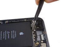
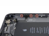
Remove the following four Phillips screws:
-
Three 2.0 mm screws holding the power button bracket in place
-
One 1.3 mm Phillips screw over the flash and microphone bracket
-
-
-
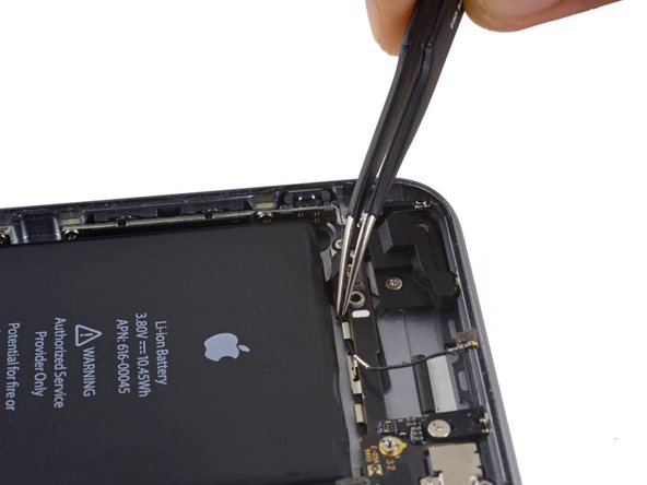
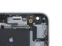
Remove the flash/microphone bracket.
-
-
-
Use the pointed end of a spudger to lift the flash out of its housing in the rear case.
-
-
-
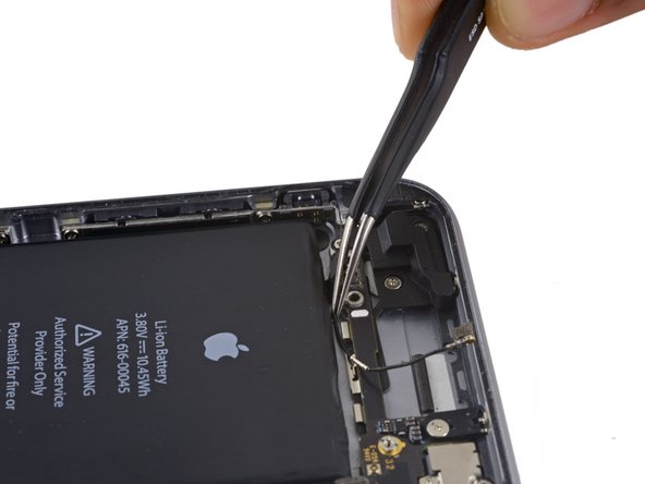
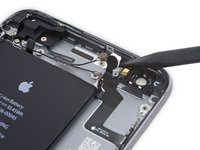
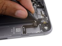
Use the flat end of a spudger to peel the power button flex cable off the rear case.
-
-
-
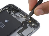
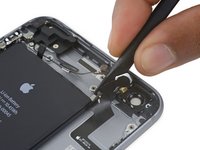
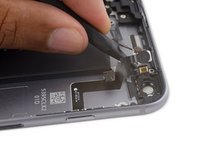
Insert the tip of a spudger underneath the microphone portion of the flex cable and gently pry it off of the rear case.
-
-
-
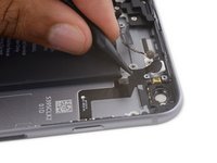
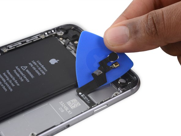
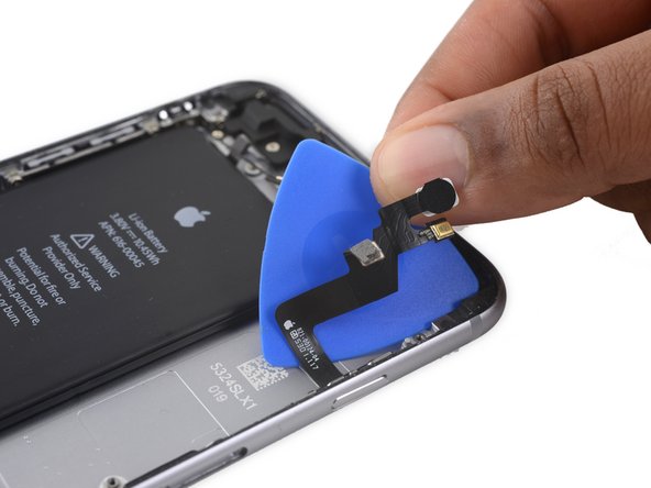
Slide an opening pick underneath the power button flex cable to pry the cable off the rear case.
-


To reassemble your device, follow these instructions in reverse order.
To reassemble your device, follow these instructions in reverse order.
crwdns2935221:0crwdne2935221:0
crwdns2935229:019crwdne2935229:0
