crwdns2915892:0crwdne2915892:0
Follow the steps in this guide to remove or replace a faulty or water-damaged logic board in an iPad mini 4 LTE.
Note that if you replace your logic board without a paired home button, you will lose Touch ID functionality.
Parts of this guide were shot with a Wi-Fi model and as such the internals may look slightly different from the LTE model. The procedure is the same for both models except where noted.
crwdns2942213:0crwdne2942213:0
-
crwdns2935267:0crwdne2935267:0Safety Glasses$3.19
-
If your display glass is cracked, keep further breakage contained and prevent bodily harm during your repair by taping the glass.
-
Lay overlapping strips of clear packing tape over the iPad's display until the whole face is covered. For particularly bad breaks, you may need to lay down two layers.
-
Do your best to follow the rest of the guide as described. However, once the glass is broken, it will likely continue to crack as you work, and you may need to use a metal prying tool to scoop the glass out.
-
-
-
Heat an iOpener and apply it to the left edge for two minutes.
-
-
-
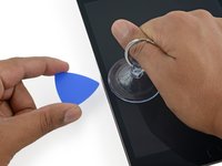
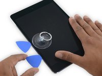
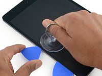
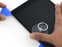
Apply a suction cup halfway up the heated side.
-
Be sure the cup is completely flat on the screen to get a tight seal.
-
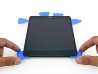
While holding the iPad down with one hand, pull up on the suction cup with strong, steady force to create a gap.
-
-
-
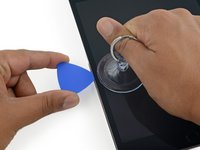
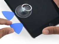
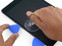
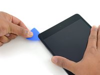
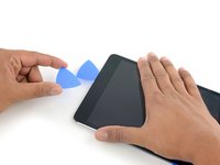
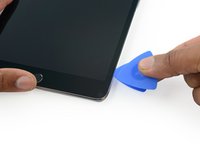
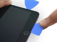
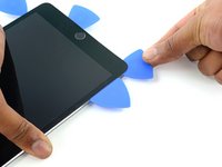
While holding the glass up with the suction cup, insert the point of an opening pick into the gap between the glass and body of the iPad.
“Don't insert the opening pick any deeper than the black bezel on the side of the display. Inserting the pick too far may damage the LCD.”
Unfortunately, you only know you have inserted it too far when you have, and you start seeing little bubble veins form between the glass screen and the LCD.
The adhesive can be very stiff/hard, and if pushing through it can result in the pick plunging into the LCD when the adhesive finally gives way.
Take your time, use alot of heat, and if you need to try and push the pick in, try and do so in a slicing motion along the edge, use the wide edge, or hold the pick so that your finger will hit the edge of the screen before the pick tip will pass the bezel.
Adhesive strips are only 1mm wide on sides. Up to 5mm wide top and bottom. I used the Isclack. Screen seemed ok bending without breaking. Worth looking for a photo of the replacement adhesive strips so you know what you have to separate. Be extra careful at the lower right corner where the cables are.
This is a failure of a guide as it doesn’t tell you to insert at a downward angle so you don’t potrude into the LCD… Now I have to spend more money to replace the screen as I pushed adhesive between the LCD and the screen even though I went no farther than a millimeter short of the screen...
can you open the right side if the left is too cracked to use a suction cup on?
This guide needs amending urgently.
You MUST NOT put the pick or whatever you are using more than 2mm under the sides of the screen, or you will cut through the adhesive tape securing the backlight assembly to the LCD glass.
This will push adhesive into the viewable area of the LCD and cause the backlight assembly to no longer be secured against the LCD fully.
I now need a new screen.
This line below from the guide is absolutely INCORRECT and will ruin your expensive display:
”Don't insert the opening pick any deeper than the black bezel on the side of the display.”
The black bezel is 5mm to 6mm wide; you MUST NOT insert anything to that depth or you will destroy your display. 2mm maximum!
thanks. will take this into account for my repair
Adab Abu -
I too damaged my display because of this absolute nonsense (The German version, which I used, still had this INCORRECT portion in it). I can't believe how long it took iFixit to update this, even though people have been reporting this for years on end. Sadly iFixit still haven't updated a variety of other things that are still at the very least high risk instructions. I just messaged them the other day, but they don't seem to care about or understand the remaining issues that this guide has. At least they updated one of the most severe things, but they just plainly told me 'I'm wrong' about the rest. I liked iFixit it so far, and I've worked on a variety of (difficult) repairs - but this experience was a very huge let down.
A few thoughts after opening a number of Mini 4’s.
1) if the display is warm enough you can squeeze the digitizer and LCD back together after a minor incursion with the opening pick and it will reseal.
2) I’ve started going in at the top just to the right of the camera (I use an iFlex to get in then switch to a pick). Then I run down either side with my fingers choked up on the pick so there only a mm or 2 sticking out. Usually after running down one side, I can get the display open enough to get the pick in behind the LCD when I do the other side
-
-
-
Reheat and reapply the iOpener to the left edge for a few minutes.
If your iPad is cold, consider leaving the iOpener on for longer than 5 minutes. The aluminum housing is a very large thermally dissipating mass and will quickly cool off the glass and make you have to start over and wait the 10 minutes to reheat. There’s a very slim window in which you’re able to insert the pick into the glass adhesive before it solidifies once again. I’ve been fighting with it for like 20 minutes following these instructions and it’s not working. You really need to leave it for longer than just 5 minutes to get the back housing hot too.
Heat is essential. I used a 3d printer’s heated set at 65 degrees. Chris Storer’s stip above saved me as you really need to let it sit for quite a while to soften the adhesive. Since I was doing a battery change, I heated both sides as the aluminum back is a huge heatsink that really sucks up the heat. Don’t try forcing it; if the suction cup isn’t pulling a gap in the screen, leave it on the heater for additional time.
Love the 3d printer idea, I hadn’t thought of that! I have used a heat gun as well but you have to be very careful to not use too much heat. Also watch for inserting the pick too far, it is really easy to delaminate glass from the display!
russ -
-
-
-
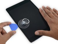
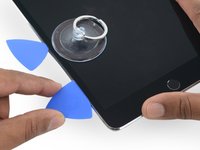
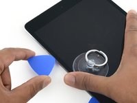
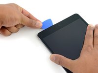
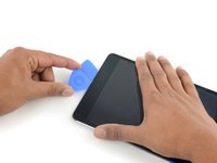
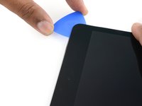
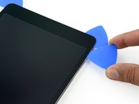
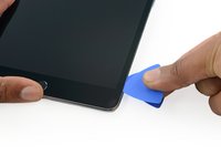
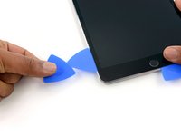
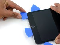
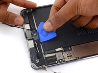
Insert a second opening pick alongside the first and slide the pick down along the edge of the iPad, releasing the adhesive as you go.
I have found that wedging a blue pry tool in between the frame and the glass can give you a better edge enough to slide the pick in.
-
-
-
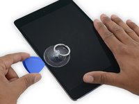
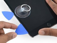
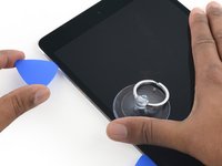
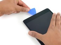
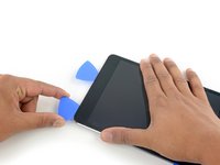
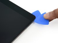
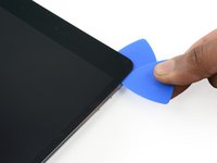
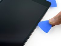
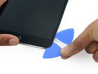
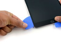
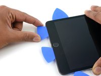
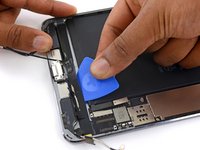
Continue moving the opening pick down the side of the display to release the adhesive.
-
If the opening pick gets stuck in the adhesive, "roll" the pick along the side of the iPad, continuing to release the adhesive.
-
-
-
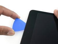
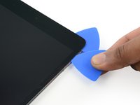
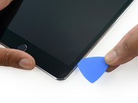
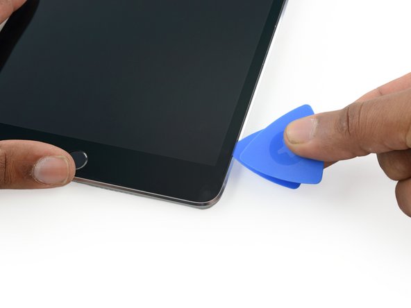
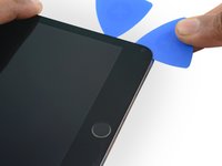
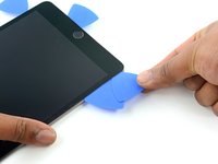
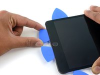
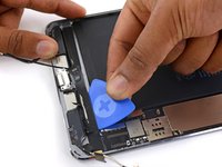
Take the first pick you inserted and slide it up toward the top corner of the iPad.
-
-
-
Reheat the iOpener and place it on the top edge of the iPad, over the front-facing camera.
-
If you have a flexible iOpener, you can bend it to heat both the upper left corner and the upper edge at the same time.
-
-
-
Slide the opening pick around the top left corner of the iPad to separate the adhesive.
-
-
-
Slide the opening pick along the top edge of the iPad, stopping just before you reach the camera.
-
As you reach the front-facing camera, pull the pick out slightly and continue sliding it across the top edge.
-
-
-
Leave the opening pick in the iPad slightly past the front-facing camera.
-
Take a second pick and insert it to the left of the camera, where the first pick just was. Slide it back to the corner to completely cut any remaining adhesive.
-
Leave the second pick in place to prevent the corner adhesive from re-sealing as it cools.
-
-
-
Insert the previous pick deeper into the iPad and slide it away from the camera toward the corner.
-
-
-
Leave the three picks in the corners of the iPad to prevent re-adhering of the front panel adhesive.
-
Reheat the iOpener and place it on the remaining long side of the iPad—along the volume and lock buttons.
-
-
-
Insert a new opening pick and slide it down the right edge of the iPad, releasing the adhesive as you go.
-
-
-
Continue sliding the opening pick down the right edge of the iPad, reheating the edge using an iOpener if necessary.
-
-
-
Leave the opening picks in place and reheat the iOpener.
-
Set the reheated iOpener on the home button end of the iPad and let it rest for a few minutes to soften the adhesive beneath the glass.
-
-
-
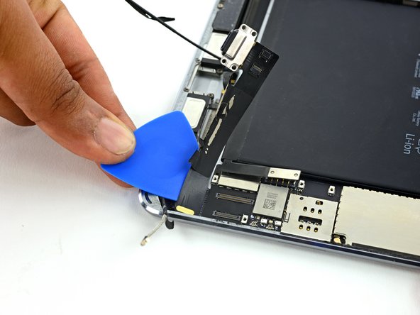
Insert a new opening pick at the bottom right corner of the display, below the last opening pick you used to slice down the right edge.
-
Rotate the new pick around the lower right corner of the device.
-
-
-
Slide the pick from the bottom right corner along the lower edge of the device. Stop about half an inch shy of the home button.
-
-
-
-
Insert a final opening pick at the lower left corner of the iPad, directly below the existing one.
-
-
-
Slide the pick around the lower left edge of the iPad.
-
-
-
Continue sliding the pick at the lower left edge of the display toward the center of the iPad, until it is roughly half an inch from the home button.
-
-
-
Twist the two picks at the top edge of the iPad to break up the last of the adhesive holding the display assembly in place.
-
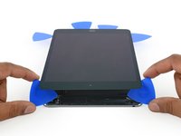
Lift the display from the top edge to open the device.
"Twist the two picks at the top edge of the iPadTwist the two picks at the top edge of the iPad "
When I did this twisting motion, and I thought I was being gentle, one of the picks cracked nearly in half. That adhesive is very strong! I probably did not cut into it far enough before applying the twisting to open the screen.
-
-
-
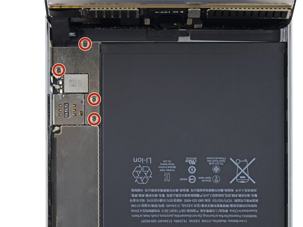
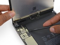
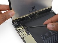
Remove the four 1.2 mm Phillips screws over the battery/display connector bracket.
What you need to do is move the display inboard up to the edge area of battery! That will relieve all the stress on the cables. Simply holding it straight up is not enough, especially later when you go back to reconnect the cables and the bracket over the connectors.
-
-
-
Remove the battery/display cable bracket.
Your bracket may look different to this. Mine had a black covering on the long edge being held between the fingers in this illustration. Same screws, same position, just a different color.
Is it the end of the world if the bracket is not reinstalled, will the device function normally or will it eventually have issues with the connectors coming loose following shock?
Note that the left had side of the bracket hooks under a lip on the edge of the case. Always recommend to replace connector brackets. If you forget and leave it out, best to buy a new set of adhesive strips for the day when the connector comes loose.
-
-
-
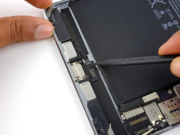
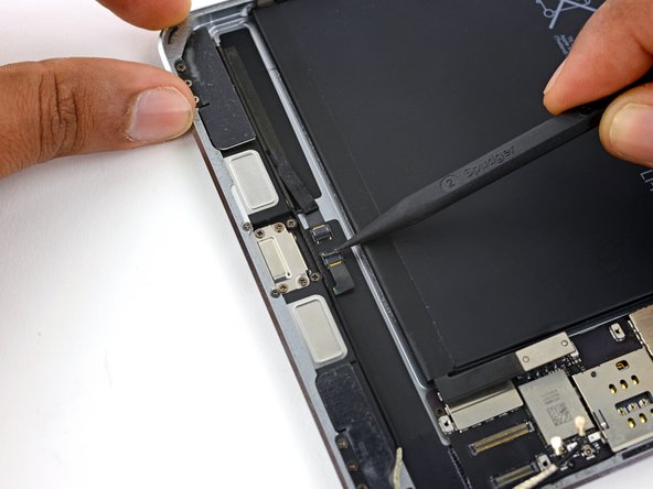
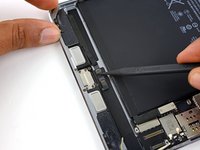
Use the flat tip of a spudger to disconnect the battery connector from its socket on the logic board.
When i was starting to disconnect the lcd to the board i hit the black film and it lit and now even the new display wont display anything how to fix it? The black film near the lcd connector.
-
-
-
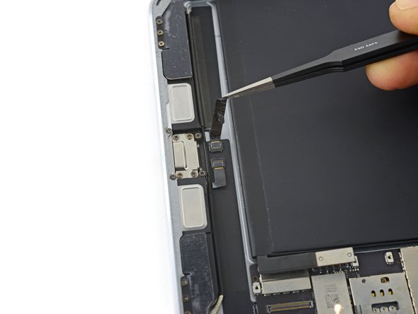
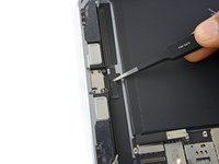
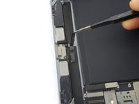
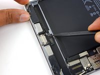
Use the pointed end of a spudger to disconnect the display data connector from its socket on the logic board.
-
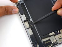
Use the pointed end of a spudger to disconnect the digitizer cable connector from its socket on the logic board.
-
-
-
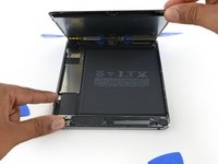
Remove the display assembly.
Ich habe eine Bücherstütze benutzt um das Display in senkrechter Position zu halten, während ich die vier Schräubchen gelöst habe.. So zieht man nicht so an den Flexkabeln….!
Because the 3-piece adhesive strips shown in the Display Adhesive Application Guide link were different from iPad Mini 4 Adhesive Strips (item code IF316-013-1), it wasn't easy to figure out the exact location of the bottom adhesive. It would be helpful to include a separate application guide or an additional picture showing the exact location of each strip) on the guide.
-
-
-
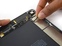
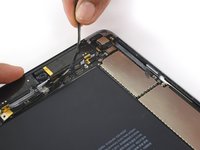
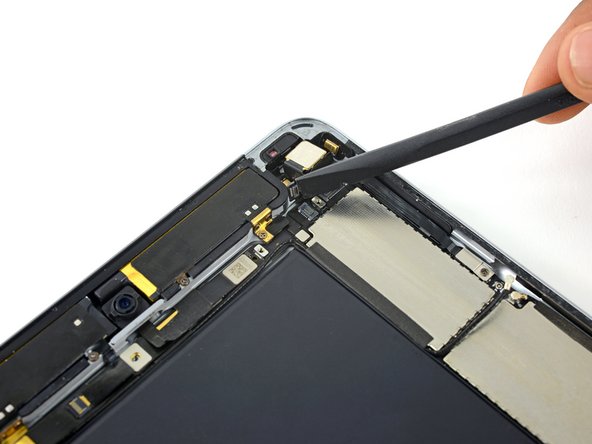
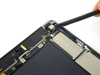
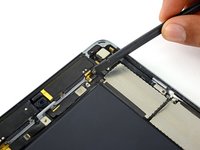
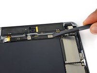
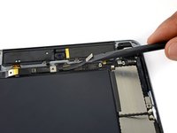
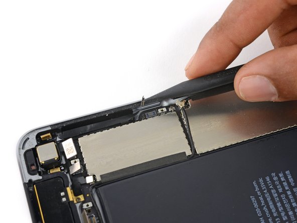
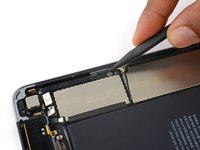
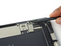
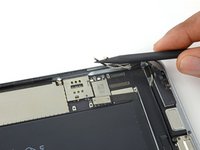
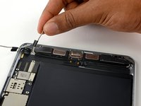
Run the pointed end of a spudger between the looped tape and the plastic cellular antenna housing to make it easier to peel the tape up.
-
-
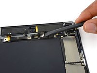
crwdns2935267:0crwdne2935267:0Tweezers$4.99
-
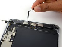
Use tweezers to peel up the looped tape adhered over the upper component cable bracket.
-
-
-
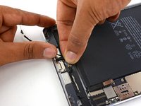
Remove the following four Phillips screws holding the upper component bracket in place:
-
Two 2.1 mm screws
-
Two 1.2 mm screws
-
-
-
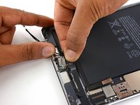
Remove the upper component cable bracket.
-
-
-
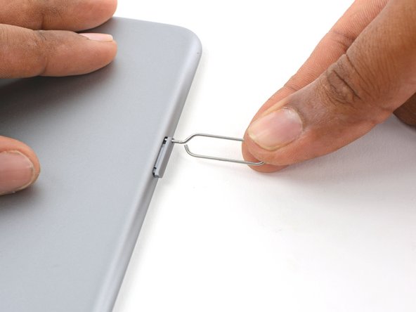
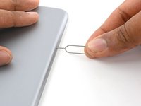
Press a paper clip or SIM eject tool into the SIM eject hole.
-
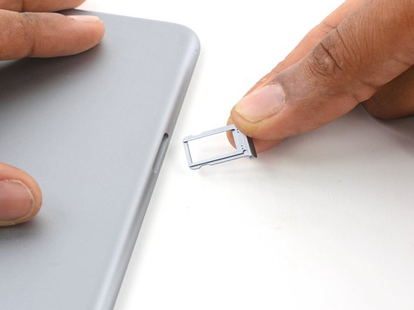
Remove the SIM card tray.
-
-
-
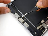
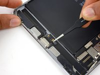
Use a spudger to disconnect the upper antenna interconnect cable from its socket on the logic board.
-
-
-
Peel the upper antenna interconnect cable up off the logic board.
-
-
-
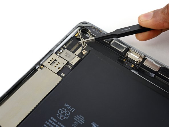
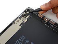
Use the flat end of a spudger to lift the rear-facing camera cable connector from its socket on the logic board.
-
Lift the sensor cable connector from its socket.
-
Disconnect the right cellular antenna from the logic board.
-
-
-
Use the flat end of a spudger to disconnect the front-facing camera press connector.
-
Lift the Facetime camera ribbon cable out of the way and disconnect the headphone jack ribbon cable directly underneath it.
-
-
-
Remove the 1.2 mm Phillips screw securing the volume control cable.
-
-
-
Remove the volume control cable bracket.
-
-
-
Use the point of a spudger to lift the volume control cable connector from its socket on the logic board.
-
Be careful to lift up only on the connector itself, not the socket on the logic board.
-
-
-
Use the point of a spudger to disconnect the two lower antenna interconnect cable connectors.
-
-
-
Remove any tape covering the ZIF connectors near the Lightning connector port.
-
-
-
Use the tip of a spudger to lift each of the two ZIF connector retaining flaps.
-
-
-
Pull each speaker cable out from its ZIF socket.
-
-
-
Peel the lower antenna interconnect cables away from the corner of the rear case.
-
-
-
Peel the left antenna interconnect cable up off the Lightning port cable.
-
-
-
Remove the four 1.5 mm Phillips screws securing the Lightning port to the rear case.
-
-
-
Begin to gently lift the Lightning connector cable up.
-
-
-
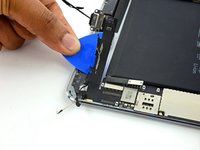
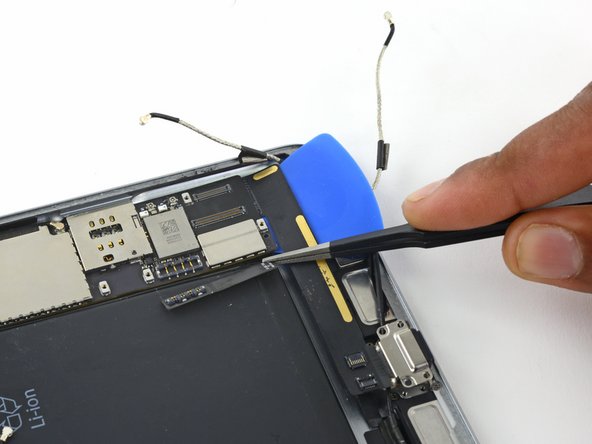
Use an opening pick to separate the adhesive connecting the lightning connector cable to the iPad case.
-
-
-
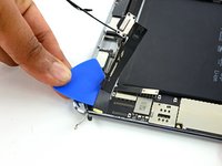
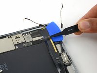
Continue to slide the pick under the Lightning port cable until you reach the end of the logic board.
-
Leave the pick in place to prevent the adhesive from re-adhering.
-
-
-
Bend back the battery connector over the battery, out of the way of the logic board.
Be extra careful with the battery connector, it tears the tape holding it very easily
-
-
-
Reheat an iOpener and lay it on the backside of the iPad near the SIM slot for at least two minutes.
-
-
-
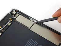
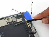
Once the adhesive has softened, carefully push the opening pick under the logic board.
I did three of these today. One LTE and two WIFI. Oddly the WIFI ones seemed to be more heavily glued. Neither of them would come up from the case at this end - I found it easier to get it started at the other end. I could only get a little bit at a time before having to put it back on the separator (hot plate). The one I was saving the logic board from, I took out the battery first t make it easier.
-
-
crwdns2935267:0crwdne2935267:0Plastic Cards$2.99
-
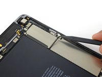
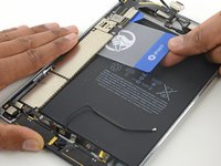
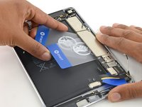
Once the opening pick has lifted a corner of the logic board, you can insert a plastic card under the board.
-
Slide the plastic card under the logic board, toward the top of the iPad, near the cameras.
-
-
-
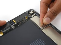
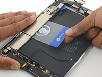
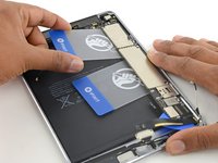
Insert a second plastic card underneath the first one.
-
Slide the second plastic card up to the top edge of the logic board.
-
-
-
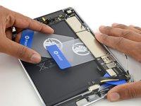
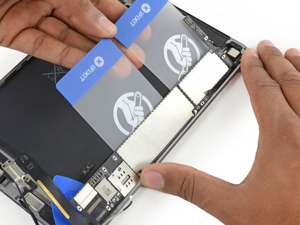
Lift up on the edges of both plastic cards to pry the logic board from the rear case.
-
-
-
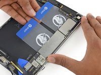
Remove the logic board assembly from the rear case.
-


To reassemble your device, follow these instructions in reverse order.
To reassemble your device, follow these instructions in reverse order.
crwdns2935221:0crwdne2935221:0
crwdns2935229:07crwdne2935229:0

crwdns2947410:01crwdne2947410:0
This guide needs amending urgently before more people destroy their LCD displays by cutting through the tape holding the backlight to the LCD glass, or pushing a pick or other tool between the LCD glass and touchscreen glass.
The guide states:
Don't insert the opening pick any deeper than the black bezel on the side of the display.
This is WRONG and will destroy your display. The black bezel is 5mm wide, this is beyond the 1mm wide adhesive and into the LCD display and backlight assembly. Do not insert anything more than 2mm down the sides of the display.
Any further than 2mm and, like me, you will be looking at a very expensive LCD display replacement.
Thanks IFIXIT.COM for publishing an incorrect guide that has destroyed my display.