
iMac Intel 27" EMC 2639 CPU Replacement

crwdns2944107:0crwdnd2944107:0Walter Galancrwdnd2944107:0crwdnd2944107:0crwdnd2944107:04crwdnd2944107:0crwdne2944107:0
crwdns2944111:0Dzi 11, 2024crwdne2944111:0
crwdns2915892:0crwdne2915892:0
crwdns2942287:0crwdne2942287:0Replace or upgrade the CPU. Don't forget to apply a new layer of thermal compound before reassembling your iMac.
Follow our thermal paste guide for instructions on cleaning and preparing the thermal surfaces and applying a new layer of thermal compound onto the CPU and GPU dies.
Before beginning any work on your iMac: Unplug the computer and press and hold the power button for ten seconds to discharge the power supply's capacitors.
Be very careful not to touch the capacitor leads or any exposed solder joints on the back of the power supply. Only handle the board by the edges.
crwdns2942213:0crwdne2942213:0
crwdns2943215:0crwdne2943215:0


crwdns2944105:0crwdne2944105:0

-
crwdns2935267:0crwdne2935267:0iMac Intel 27" Cardboard Service Wedge$4.99
-
With the hinge free to move, the iMac will be unbalanced and hard to work on. Repairs can be completed with the iMac laying down, but are faster and easier with an iMac service wedge.
-
If you are using the iFixit cardboard service wedge, follow these assembly directions to put it together.
-
-
-
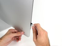
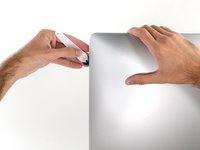
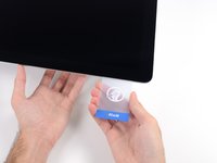
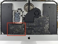
Starting on the left of the display, near the power button, insert the iMac Opening Tool into the gap between the glass panel and the rear case.
-
-
-
Use the tool like a pizza cutter—roll it along through the gap, and it will cut the foam adhesive through the center.
-
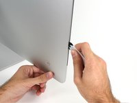
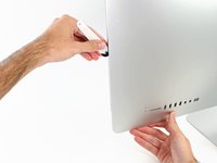
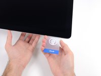
Run the tool up along the left side of the display.
-
-
-
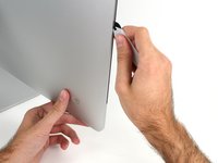
Continue wheeling the tool up around the top left corner.
-
-
-
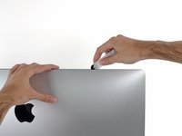
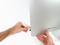
Cut the adhesive along the top left of the display.
-
-
-
Continue along the top of the display.
-
-
-
Push the tool around the top right corner of the display.
-
-
-
Wheel the tool down along the right side of the display.
-
-
-
Finish pushing the opening tool to the bottom of the right side of the display.
-
-
crwdns2935267:0crwdne2935267:0Plastic Cards$2.99
-
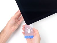
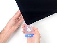
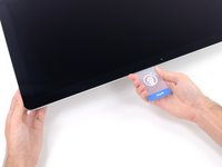
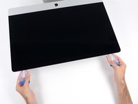
Set the iMac face-up on a table.
-
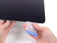
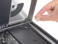
Starting from the top right corner of the iMac, insert a plastic card between the display and frame.
I actually DESTROYED my display (black vertical strips) by pushing the card in a bit TOO DEEP. So it is REALLY important to insert the card only a bit (1-2mm) more than the cutter wheel, in particular at the top side, where many flat cables connect the panel with the PCB. These can be damaged very easily!
Same thing with me…. Pushed cards to far…. new panel needed…€600…..
i think ifixit needs to place a bigger caveat, as I have missed it the first time
i successfully upgraded two imacs. one opened with ifixit pizza knife and another with a regular paper knife. however, when i had to open the first one once again i broke its screen glass. it seems ifixit adhesive strips are too strong. next time i’ll try to use heater to weaken glue tension.
I broke one too. And even if you think you did it correctly, you’ll not be able to see where you might have gone too far. You would think it’s very protected behind that metal plate, but no. Take special care with this offence to “right to repair” This should have been designed WAY better. I mean replacing a hardrive that is very likely to fail over the course of time, or even a simple desire to upgrade to an ssd!.
Bummer
HINT: If you turn the card and use the blue part of it, then you can avoid going to deep: no further then the blue part …
On the cards I got with my iFixit kit, the blue part was way bigger than 9.5mm — closer to 20mm!
I made a line 9mm from the edge of each of my cards and used that as a guide.
I’m thinking I might just use vinyl tape to keep the screen in place for at least a little while after an upgrade. The extra strength of the replacement tape sounds scary.
I wrapped two layers of vinyl electrical tape around the short side of an old gift card 3/8” from the edge. This “stop" prevented the card from going in too far. The card really helps to break the panel free.
This is a good tip!
Great idea! Wish I had read this before doing it. My less then optimal solution was to draw lines 3/8” around the cards, not as safe as your fix, but fast.
Umm.. I’m not sure that I’d recommend using a repurposed credit card to open the display - I found that using the “pizza tool” to cut the old adhesive then using a pair of suction cups to gently pull the display up worked perfectly well.
surely the card should have been designed such not to go further than certain distance with a barrier band.
The cards don’t have any means to control the depth, its your skills which control it. Its no different from how you use a knife to cut your chicken up when you serve it for dinner.
DanJ -
The pizza roller tool is enough to cut through the adhesive. You dont need to cut in a lot further. So the cards are really not necessary.
might be a stupid question but would credit cards or state ids work too?
You need the pizza cutter! The cards are used to hold the display off of the case frame.
As for as using old credit cards and useless ID cards sure they will work. I wouldn’t use anything important ;-}
DanJ -
No problems. I used two old credit cards and marked out a line using permanent marker so it was at the same depth as stipulated on this page. I even pushed it in a little deeper and no issues.
Go very slowly when doing these steps.
-
-
-
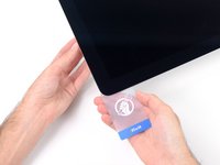
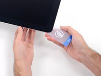
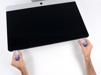
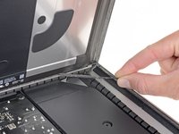
Gently twist the plastic card to open the space between the display and frame, and cut any remaining adhesive near the corner.
-
-
-
Slide the card toward the center of the display, to cut any remaining adhesive.
-
-
-
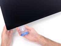
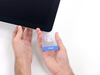
Put the card into the corner again and let it stay there to keep the adhesive from resettling.
-
-
-
Insert a second card into the gap between the display and frame in the top left corner.
-
-
-
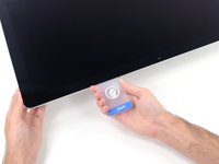
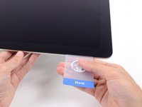
Gently twist the card, slightly increasing the space between the display and frame.
-
-
-
Slide the plastic card toward the center, again stopping just before the iSight camera.
-
-
-
Insert the card back into the top left corner.
-
-
-
With the cards inserted as shown near the corners, gently twist the cards to increase the gap between display and case.
-
If there are any sections that seem to stick and won't separate, stop twisting and use one of the cards to cut the adhesive in the problem area.
-
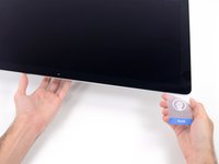
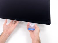
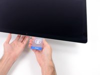
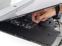
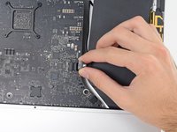
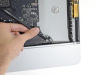
Begin to lift the top of the display up from the frame.
-
-
-
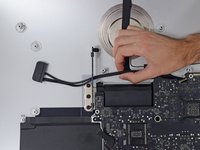
While holding the display up with one hand, use the other to unplug the display power cable.
-
-
-
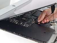
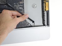
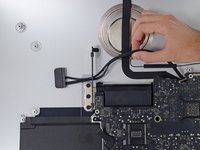
Flip up the metal retaining bracket on the display data cable.
-
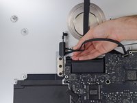
Disconnect the display data cable.
-
-
-
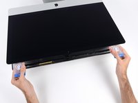
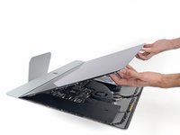
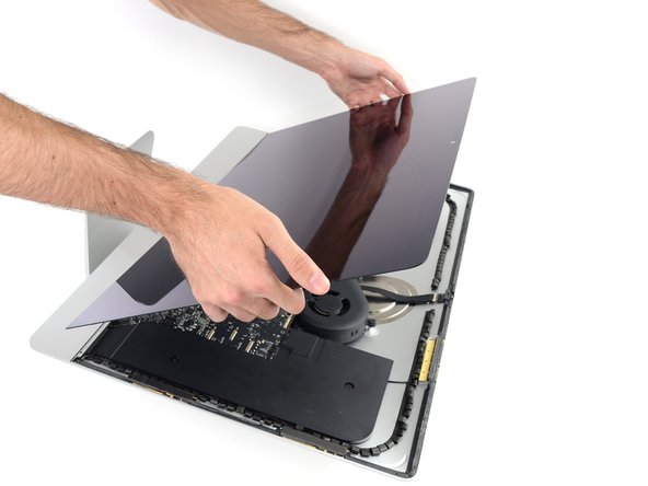
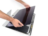
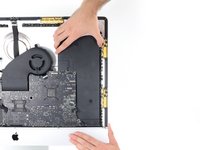
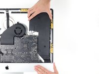
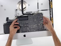
Lift the display up to a near-vertical position.
-
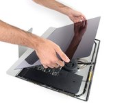
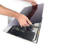
Remove as much of the adhesive as possible by grabbing it at the outer edges, and then pulling or rolling it towards the middle.
-
-
-
If necessary, a plastic card can be used to cut any remaining sections of the bottom adhesive strip.
-
-
-
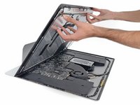
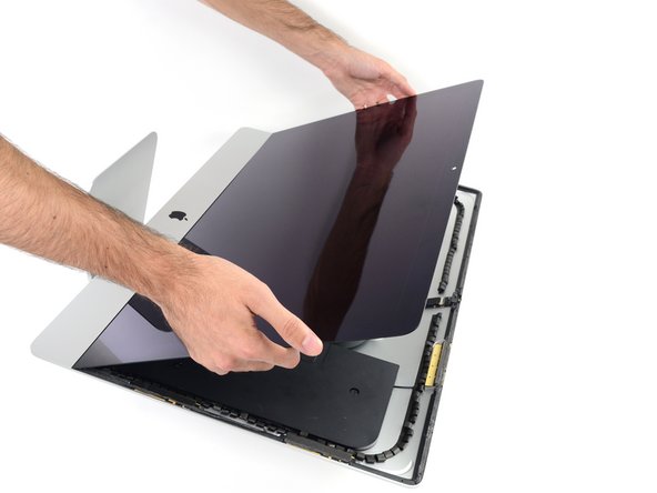
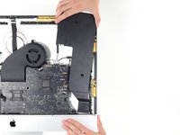
Lift the display up from the frame and remove it from the iMac. Lay the display face down on a flat, soft surface.
-
It may be necessary to slowly lift from one side, to peel against the remaining adhesive.
-
-
-
If there is a wire or cable underneath adhesive tape, always pull the tape off first.
-
If the cable is glued to the chassis, use a heated iOpener or a hair dryer to soften the adhesive first. You can then slide an opening pick underneath the cable to loosen it. Never pull directly on the delicate connectors.
-
Slide an opening pick underneath the foam cushion pieces to separate them from the display, and gently pull them off. You may need some double sided tape to re-attach them to the new display.
-
-
-
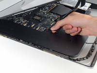
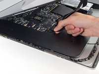
Use a Phillips screwdriver to remove the nine 3.2 mm screws securing the support bracket.
-
You may need to peel up the display adhesive lining the bottom edge of the iMac enclosure to access the screws.
-
-
-
Remove the lower support bracket (a.k.a. "chin strap") from the iMac enclosure.
-
Position the bracket diagonally.
-
Secure the rightmost screw enough to hold the bracket in place; keep it loose for now so the bracket can pivot.
-
Swing the left side of the bracket down until it sits horizontally in its original position.
-
Starting with the leftmost screw, install and tighten the remaining screws.
-
-
-
Remove two 10 mm T10 screws.
-
-
-
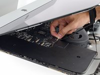
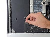
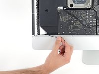
Unplug the left speaker cable by pulling it straight up out of its socket on the logic board.
-
De-route the cable from the gap between the hard drive and logic board.
-
-
-
Use a spudger to disconnect the power button connector from its socket on the logic board.
-
-
-
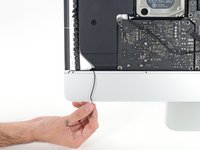
Lift the left speaker straight up, until the power button cable is exposed (about 0.5 inches).
-
-
-
Gently de-route the power button cable from its groove in the left speaker.
-
-
-
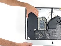
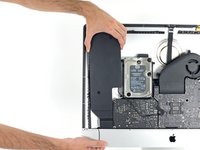
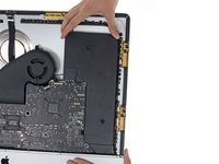
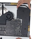
Lift the left speaker straight up and remove it from the iMac.
-
Push from the connector end as you pull from the speaker end to thread the cable under the hard drive's right bracket.
-
-
-
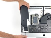
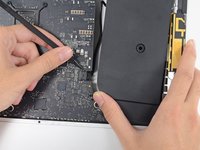
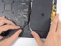
Pull straight up on the SATA data/power cable to disconnect it from the drive.
-
-
-
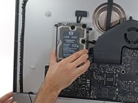
Remove two 7.3 mm T10 screws securing the left hard drive bracket to the rear case.
-
-
-
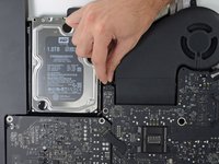
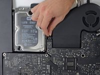
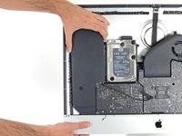
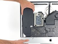
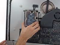
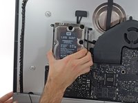
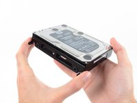
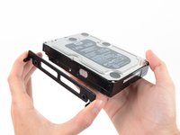
Grab the hard drive and left hard drive bracket together.
-
Tilt the left side up away from the rear case, and slide the assembly to the left.
-
Remove the hard drive and left hard drive bracket from the iMac.
-
-
-
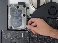
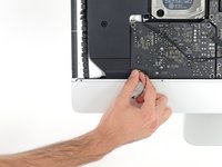
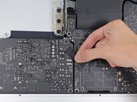
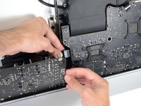
Disconnect the power supply control cable from the power supply.
-
-
-
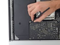
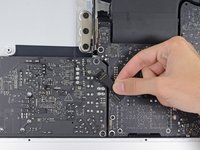
Remove the following four screws securing the power supply to the rear case (size T8 or T10 depending on the exact model):
-
Two 23.7 mm Torx screws
-
Two 7.3 mm Torx screws
-
-
-
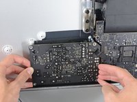
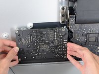
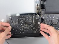
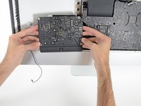
Move the power supply board towards the left edge of the case and up to free it from the notch in the logic board.
-
-
-
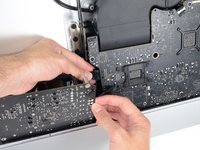
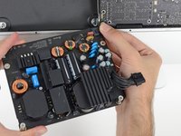
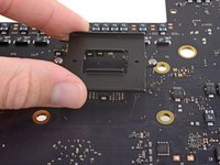
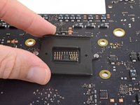
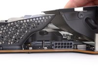
Depress the tab on the DC power cable connector, then pull it straight out of its socket on the back of the logic board.
-
-
-
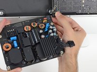
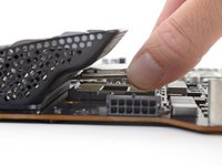
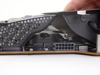
Flip the top of the power supply towards you, like opening a mailbox, to reveal the AC inlet cable connector.
-
Disconnect the AC inlet cable connector.
-
-
-
Remove two 10.0 mm T10 screws.
-
-
-
Gently rock the right speaker slightly to the right, to allow access to its cable's connection on the logic board.
-
-
-
Use a spudger to loosen the right speaker cable's connector from its socket on the logic board.
-
Pull the connector to the right to remove it from its socket.
-
-
-
Lift the speaker straight up and remove it from the iMac.
-
-
-
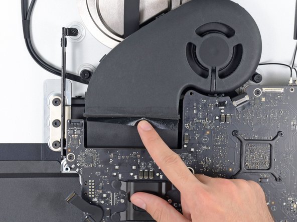
Use the tip of a spudger to disconnect the fan cable's connector from its socket on the logic board.
-
-
-
Peel the black tape connecting the fan to the exhaust duct back slightly.
-
Leave the tape in place on the exhaust duct—you only need to expose the joint to free the fan.
-
-
-
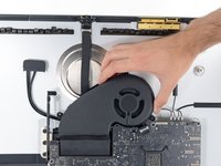
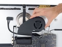
Remove three 12.4 mm T10 screws securing the fan to the rear case.
-
-
-
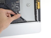
Use the flat end of a spudger to disconnect each of the four antenna connectors from the AirPort/Bluetooth card.
-
Leftmost
-
Top
-
Upper right
-
Lower right
-
-
-
Flip up the metal retaining bracket on the iSight camera cable.
-
Pull the camera cable connector straight out of its socket, toward the top of the iMac.
-
-
-
Use the flat end of a spudger to disconnect the headphone jack cable connector from its socket on the logic board.
-
Gently push the cable out of the way.
-
-
-
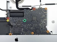
Remove the following screws from the front of the logic board:
-
Two 23.7 mm T10 screws
-
Four 7.4 mm T10 screws
-
One 20.8 mm T25 spacer screw
-
One captive T10 screw
-
-
-
Pull the cable and connector through the right hard drive bracket. Move the cable to the right side of the iMac, out of the way of the exhaust port.
-
-
-
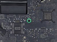
Remove two 5.7 mm T10 screws from the top of the heat sink exhaust duct.
-
-
-
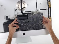
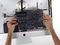
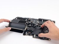
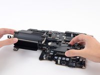
Tilt the logic board slightly forward.
-
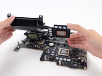
Lift the logic board straight up and out of the iMac. Be careful not to snag on any of the screw posts attached to the inside of the rear case.
-
-
-
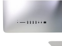
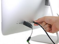
When reassembling your iMac, be very careful to align the exterior I/O ports correctly. The logic board can sit crooked even when secured with all its screws.
-
You can use a USB flashdrive or ethernet cable to ensure the logic board is seated correctly while you screw it in.
-
-
-
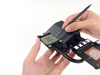
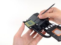
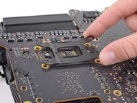
Remove the four 7.5 mm T8 screws from behind the GPU on the logic board.
-
-
-
Remove the bracket from behind the GPU heat sink.
-
-
-
Remove four black stickers from the back of the CPU heat sink.
-
-
-
Remove four 12.3 mm T10 screws from the back of the CPU heat sink.
-
-
-
Remove the spring plate from behind the CPU heat sink.
-
Lift and remove the backing plate from behind the CPU heat sink. The backing plate has two posts that fit into alignment holes in the logic board.
-
-
-
Lift the heat sink up from the logic board.
-
-
-
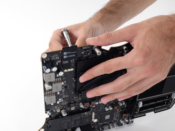
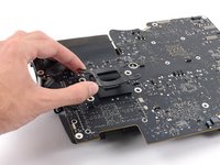
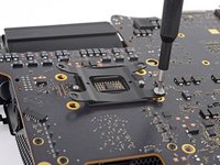
Insert the flat end of a spudger between the CPU and heat sink.
-
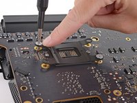
Gently pry the CPU up by slightly twisting the spudger.
-
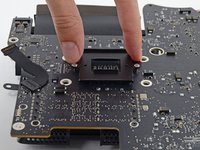
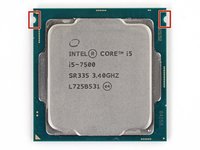
Remove the CPU from the heat sink. Be careful not to touch the contacts.
-
-
-
Replace the backing plate on the motherboard, and hold it in place while you turn the board over so the side with the CPU socket faces up.
-
-
-
Before installing the heat sink, see our thermal paste guide for instructions on cleaning and preparing the thermal surfaces and applying a new layer of thermal compound onto the CPU and GPU dies.
-
For the VRAM chips surrounding the GPU, install thermal pads or a thick thermal paste such as thermal putty or K5-PRO, rather than regular thermal paste.
-
The CPU
-
The GPU
-
The VRAM chips
-
The heat sink plates
-
-
-
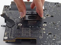
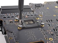
Align the CPU so that the cutouts in the CPU match the tabs in the socket.
-
Gently place the CPU in the socket. Try to set it straight down and avoid sliding it around once it is in the socket.
-
-
-
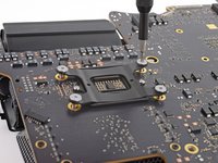
Align the holes on the CPU section of the heat sink with the pins on the backing plate.
-
Set the heat sink straight down on the CPU, GPU, and VRAM chips.
-
-
-
Keeping inward pressure on both the heat sink and the backing plate, flip the logic board over so the heat sink faces down.
-
-
-
Place the spring plate on the backing plate.
-
Carefully thread one of the CPU heat sink screws slightly into the heat sink so that just a couple threads are engaged.
-
Press down on the opposite corner of the spring plate from where you just installed a screw.
-
While holding the corner down, thread another screw into that corner of the heat sink, again just tightening it until a couple threads are engaged.
-
-
-
Repeat the process of pressing down the spring plate and slightly threading in the screws to install the remaining two heat sink screws.
-
Tighten the screws down a little at a time in the same order that you installed them—in an "X" pattern starting at one corner and then crossing to the opposite corner.
-


To reassemble your device, follow these instructions in reverse and use our Adhesive Strips Guide to reattach the display glass.
Take your e-waste to an R2 or e-Stewards certified recycler.
Repair didn’t go as planned? Try some basic troubleshooting, or ask our Answers community for help.
To reassemble your device, follow these instructions in reverse and use our Adhesive Strips Guide to reattach the display glass.
Take your e-waste to an R2 or e-Stewards certified recycler.
Repair didn’t go as planned? Try some basic troubleshooting, or ask our Answers community for help.
crwdns2935221:0crwdne2935221:0
crwdns2935229:040crwdne2935229:0
crwdns2947821:0crwdne2947821:0
crwdns2947823:0crwdne2947823:0


crwdns2947412:027crwdne2947412:0
i7 processor that you can put on a Imac 2013?
The thermal compound/paste that is used by Apple on the GPU and memory is less than stellar. I would highly recommend stressing the GPU Memory gap in this guide. As you can see in the images of the cooler, specifically the GPU side, apple uses a white paste compound for thermal transfer. The problem is that the cooler does not contact the memory for the GPU. Once you remove the cooler it breaks the compound in several spots, and it will never be as good as it was unless care is made, and you are aware of this prior to re-installation.
Furthermore, with the GTX775M and GTX780M equipped iMacs, the temperatures are already above normal without removing the cooler. If you try and push these chips with the added memory in the latest generation games you will get artifacts from overheating. Due to the gap between the memory and the cooler you are also unable to use Arctic Silver as a remedy, as the gap is too much, with the logic board being vertical. (Risking seepage down the board, which I have already seen when performing the proper fix on another iMac) The coverage and type of thermal compound Apple is using is not sufficient. In the factory state the thermal compound is centered on the memory, however only 40% of the actual module comes in contact of the memory and the cooler. What I have done on my iMac and a few others so far is use thermal tape.
Hello, i am upgradinf the imac at the moment and want to renew the thermal paste.
For the vram i want to use the thermal tape, could you twll me with thickness you used?
YES, I F*&^* hate thermal tape when compared to quality compound. With this only exception, the tape is more effective than the stock compound, and it is quarantined to make 100% contact, while dissipating heat properly. I have seen a drop of 15% under heavy use on the GPU since using the tape. YOU do not want to use cheap thermal tape! Standard tape only has a 3-5 watt thermal conductivity, which is equal to or less than a standard compound. You can go through frozencpu.com and purchase Fujipoly Extreme Thermal Pads which have a rating of 11. For use on the 27" iMacs, I went with 100 x 15 x 1.5 and (2) are needed to do completely cover both sides of the memory banks on the logic board.
Please, if you remove the cooler to replace the CPU you have to be aware of the GPU and the gap involved on the memory chips, and the potential of further gaps upon re-installation.
Are you suggesting that you used this 11kw tape on both the GPU and the GPU Memory modules?
I brought that tape but 1.5mm is way too tall and chose not to use it after all on my 27' 2013 14,2 model. Instead used 11kw X1 Extreme Fusion paste from Master Cooler. Its non-conductive so don't have to worry about short circuits. Its also very thick so doesn't run. I used the "small pea" technique on the GPU and GPU memory dims. For the actual CPU which I upgraded from the base i5 to a i7 4771 I used the "Thin line" technique.
AW H -
Prior to improving the thermal transfer on the GPU memory I have seen elevated temperatures and graphic artifacts when pushing the graphics to the max, after doing it this way I have experienced no issues and lower temps. As a side note with all thermal tapes they have a tendency to have a shorter effective lifespan than quality compound, but I don't keep computers long enough to be concerned about it. I would suggest a 2yr replacement interval if you choose to keep it for extended timeframes.
Enjoy!
Please also add to guide: DO NOT USE ARTIC SILVER ON THE GPU MEMORY!, yes i know i could just edit it but i'm confident you will read this info^
Thanks Walter!
I'm confused...are you saying Arctic Silver 5 should not be used for replacing the thermal compound on the iMac CPU? Or are you correcting a mistake from a comment from earlier. Why would you use thermal compound on the GPU or memory?
kazoodac -
Thank you tjk4.
I recently upgraded the CPU to my Late 2013 27" imac. When i took the heat sink off, thermal compound from the GPU chips was used between the heat sink and the chips. It was just a bit more of it to cover the gap you specified earlier. I got a thermal pad, the only one I could find in my country was the 6w/mK made by Arctic. It was a square pad, 50mmx50mm and 1.5mm thick. I just placed it over the entire chips and I cut just a little small square in one of the sides where no chip was present.
Problem is now my iMac kicks the fan at 1800rpm whenever I do a bit of intensive work., photoshop etc. It did not do that previously with my i5 processor nor my 21 late 2013 with IRIS gpu, using the CPU close to 100%.
I can only guess that there may be a minor gap between the cooler and the surrounding memory chips. If you go too thick on the thermal pad for the GPU it will create a gap between the cooler and the surrounding memory modules. I had to experiment with several sizes and compounds to find the best fit. It does sound like a memory resistance due to the timing, as it would take a few more cycles for the GPU to activate the fans.
tjk4 -
Did you use the thermal tape on just the GPU memory modules or both memory and GPU itself? I made that mistake and theres no contact from the heatsink to the GPU so it overheats as the thermal pads of 1.5mm are too tall! (at least on 27" 2013 14,2 models) I had to redo mine and just used quality 11kw paste which is non-conductive so no worries of short circuiting from spillage on everything. Temps are all good now.
AW H -
I still couldn't decide which type of thermal interface I should use: thermal compound or thermal pad. However, there are some details I'd like you to tell me.
*
If thermal pad is chosen (for example - Fujipoly 17.0 W/mK):
- what is actual gap between GPU memory and heat sink in millimeters? Is 1,5mm thick pad ok or not?
- what is actual gap between GPU chip and heat sink in millimeters? Is non-conductive thermal compound most preferred option or thermal pad is the best choice?
*
If alternative thermal compound is chosen:
- How many grams of it is enough to fill all of the gaps between GPU chip/memory and heat sinks?
Thanks!
3426895 -
PART II:
Do you think the 11w pad makes for such a big difference? These are my current temps, http://autoeducare.ro/foto/screen.png
I think it is better to use a good compound and using the same amount of it, like Apple did, to fit into the sheatsink and chip space. For me it worked better the way they did it, but I did not check the GPU temps before to be able to prove it, the fans were very very silent though.
what app did you use for system info/temps in your screenshot?
Armen M -
What are upgrade options for CPU on this late 2013 iMac 27"?
What is max/best CPU to upgrade to?
Where does one purchase the actual compatible CPU? (standard Intel CPU...boxed vs. OEM...)
"iMac27" 2013" for CPU and GPU I used "Thermal Grizzly Hydronaut" paste and "Fujipoly extreme plus (14W/mK)" 0.5mm thick for GPU Memory.
You need 2 strips 100mm x15mm. You can buy them on ebay.
Don't know if the heatsink height is different for the 2015 model but .5mm was a touch too low for me. If you have a 2015 (same heatsink design as instructions here) and are going the pad route get the 1.0mm. Also you don't need two strips if you just cut the single strip on each - memory chip is 12mm x 15mm so one 100mm strip will do the job. I got K5 pro instead, probably doesnt perform as well as the pad but pads were pricey $ and didnt want to risk another not fitting.
Charles -
I have a late 2013 iMac 27 inch and want to update to a ssd and change the i5 processor to a i7 processor. What is the best ssd for mac and where can I get the newer compatible i7 processor?
Can one use a Xeon CPU instead of i7? I got the iMac27”14,2 and was wondering if one can put a Xeon instead one of the i5 or i7 series.
Is there a list somewhere of current (late 2017) processors that would work in the Late 2013 iMacs?
Hi,
I have made a screw sheet for this guide. It made tracking the screws a lot easier since they are almost all of a different length! Take a look and tell me what you think.
I have a 14-2 Imac, late 2013 with the I7, my understanding is that cpu is a 4th generation. Is it possible to upgrade the motherboard and CPU to something more recent?
Dear Sir, I hope You Help me, I got a problem Now. I just follow your instruction. unfortunately, my iMac 2013/27 inch can't reboot. just I can hear the sound (beeping) I use intel core i7 4771, OWC aura pro x2 480 GB, OWC Memory 32 GB DDR 3L, Each 8 GB, Mastergel pro v2 High Thermal compund, pls give me the solution. I am a great full to you.
I read this about the beeping, read right to the end of the 2 pages. Hope it helps https://forums.tomshardware.com/threads/...
Tengo entendido q se puede actualizar el procesador a un I7 consulta saben que modelo de procesador es compatible
Acho que o suporte do processador foi montado do lado errado nessas fotos. Tenho um IMAC igual que nunca foi aberto, e esse suporte estava montadno do outro lado.