crwdns2915892:0crwdne2915892:0
This guide shows the hidden screws you must remove when replacing the keyboard.
crwdns2942213:0crwdne2942213:0
-
-
Use your thumbs to push the two battery retaining tabs away from the battery.
-
The battery should pop up enough to rotate it toward yourself and lift it out of the lower case.
-
-
-
Remove the three 2.3 mm Phillips screws securing the memory cover to the lower case.
-
-
-
Lift the memory cover slightly and pull it toward yourself to remove it from the lower case.
-
-
-
Remove the following ten screws:
-
Two 14.7 mm shouldered Phillips.
-
Three 12.3 mm Phillips.
-
One 3.8 mm T8 Torx.
-
One 6.8 mm T8 Torx.
-
Three 1.3 mm Phillips.
-
-
-
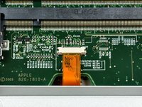
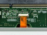
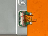
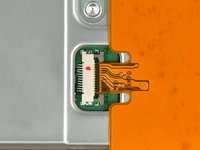
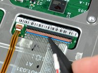
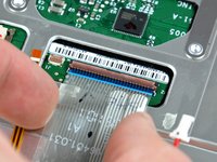
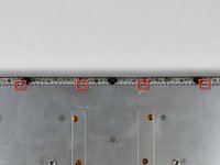
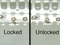
Use your fingernails to separate the ZIF cable lock away from its socket. (Move the two brown bits down 1mm)
The ZIF cable locks are the little grey pieces seen on the cable-side ends of the white bar. They will slide, as per detailed picture, toward the cable.
Where could I get a whole replacement for this connector ? Mine came off the motherboard
-
-
-
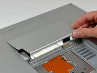
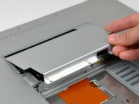
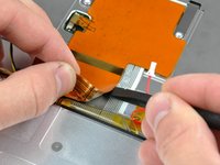
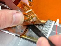
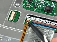
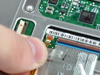
Use the tip of a spudger to slide the trackpad ribbon cable out of its socket.
-
-
-
Remove the four 3.4 mm Phillips screws from the PC card side of the PowerBook.
-
-
-
Remove the four 3.4 mm Phillips screws from the DVI connector side of the PowerBook.
-
-
-
-
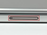
Depress the display latch release button and open your display.
-
-
-
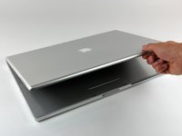
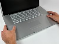
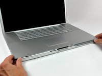
Starting near the display, lift the upper case straight up off the lower case, minding any cables that may get caught.
Sometimes the "tags"/"lugs" that are around the edge of the top & bottom frame, be careful not to bend them as when putting back the covers they will not merge. I used a screwdriver to poke through the hole the screw was supposed go in & push against the "inside nut" to let the tag from the top slide down between the 2 tags. The "inside nut" is like the one right next to the ribbon cable as shown in Dia.14. The screws are from Dia. 7&8.
in what direction does one move the ZIF cable lock? what/where is its socket?
When putting the machine back together (following steps in reverse), make sure the trackpad ribbon cable comes through the underside of the computer — there is an opening that the cable needs to go through and you will want to “thread the needle” with the cable before securing the upper case again.
At the end of these instructions, Jimbo Combo also mentions this, but it should be repeated.
Because the trackpad/keyboard cable is part of the top face/keyboard/trackpad assembly, it’s actually a PITA when doing reassembly.
One way to make this step simple is to do the following:
1. straighten the Zif cable removing all of the bends that is probably has in it.
2. Start putting the top face/keyboard/trackpad assembly on, starting with the edge AWAY from the display.
3. Place the laptop on it’s side, and thread the cable through the opening, using tweezers if necessary so that it fully goes through the opening in the case.
4. Place the laptop back to the way it was and proceed.
-
-
-
Remove the two Phillips screws securing the electronic track pad button to the lower case.
-
-
-
Use your fingernails or the tip of a spudger to separate the ZIF cable lock from its socket.
-
-
-
Use the tip of a spudger to pull the track pad ribbon cable out of its socket.
-
-
-
Disconnect both of the following connectors from the logic board:
-
Sleep sensor cable.
-
Power button cable.
-
-
-
Starting near the keyboard, use the flat end of a spudger to help separate the adhesive as you peel back the track pad ribbon cable.
Maybe it was my bad luck but I had to remove a lot of glue. It was hard, and more considering it is a "very fragile and easily to torn" cable. It helped to use a bit of warm air to soften the glue. I didn't remove all the track pad ribbon cable. Just what it was needed to reach the keyboard connectors.
-
-
-
Use the tip of a spudger to pry up the ribbon cable retaining flaps on both the keyboard and backlight ribbon cable sockets.
-
-
-
Pull both the keyboard and backlight ribbon cables out of their sockets.
-
-
-
Remove the large protective sticker from the underside of the keyboard enclosure on the lower case.
-
-
-
Use the tip of a spudger to bend each of the four keyboard lock tabs away from the underside of the keyboard enclosure on the lower case.
-
-
-
Remove the ten short Phillips screws securing the keyboard to the lower case.
-
-
-
Use the tip of a spudger to push a screw lug near the center of the keyboard, separating it from the lower case.
-
-
-
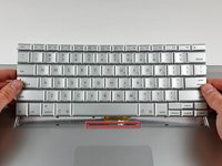
Bow the keyboard out slightly to release the two tabs near the upper corner on each side of the keyboard.
-
Rotate the keyboard toward yourself and lift it out of the upper case.
-


To reassemble your device, follow these instructions in reverse order.
To reassemble your device, follow these instructions in reverse order.
crwdns2935221:0crwdne2935221:0
crwdns2935229:03crwdne2935229:0
crwdns2935103:0crwdne2935103:0

crwdns2947412:02crwdne2947412:0
Excellent detailed instructions and cautions. Even the magnified pictures are very good. A bit more complicated than a Dell or Toshiba. Mahalo.
there’s a connector for the power button on the orange ribbon that doesn’t slip through slit - WTF?