crwdns2915892:0crwdne2915892:0
This guide shows how to remove and replace the screen and digitizer assembly for the OnePlus 5.
Use this guide for screens that come pre-mounted on a frame.
This procedure requires significant disassembly, including battery replacement, and transferring small parts from the old screen to the replacement. The two most difficult parts are getting the frame clips of the back cover free, and not damaging the fingerprint scanner cable.
Some guide images will show the dual rear-facing camera module already removed from the phone. You do not need to remove it for this procedure.
If your battery is swollen, take appropriate precautions.
For your safety, discharge your battery below 25% before disassembling your phone. This reduces the risk of a dangerous thermal event if the battery is accidentally damaged during the repair.
crwdns2942213:0crwdne2942213:0
-
-
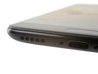
Insert a SIM card eject tool, bit, or a straightened paperclip into the small hole below the SIM card tray, located near the rear cameras on the edge of the phone.
-
Press firmly to eject the tray.
-
-
-
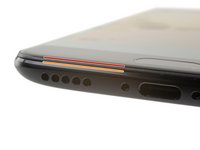
Remove the two 2.6 mm T2 screws straddling the USB-C port on the bottom edge of the phone.
What are the reference of the screws ? They are missing in the one I bought !
Hi Yôken,
They help hold the back cover on. Most of the time, the clips are enough to hold the phone together.
Just FYI, for whatever reason my brand new OnePlus 5 had 0,8 mm stars screws instead of T2 Torx.
Same here, T2 doesn’t fit the screws on my Oneplus 5. More like T1’s
Definitely T2 for me. Do watch out during assembly. I have a feeling that it’s easy to strip these.
T2 for me too. It was missing in my kit and iFixit sent it later when I asked them about it.
-
-
-
Display panel seam: This seam is part of the display assembly. Do not pry at this seam, or you will separate and damage the display panel.
-
Frame seam: This is where the plastic frame meets the back cover. Only pry at this seam.
-
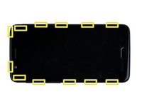
There are twelve clips that hold the frame against the rear case. Be aware of their location as you pry the back cover off in the following steps.
-
-
-
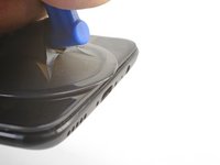
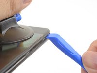
Place a suction cup near the bottom edge of the display.
-
Pull on the suction cup with strong steady force.
-
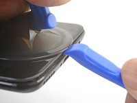
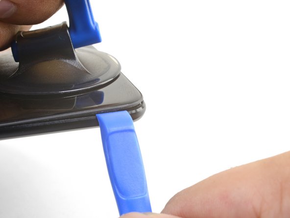
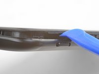
Press the edge of an opening tool straight into the frame seam near the suction cup until the edge wedges between the plastic frame and the back cover's lip.
I found pushing open the frame seam at the corner works better than pushing from the middle like it is shown in the pictures
I found the suction cup to be more of a hindrance and kept hitting the power button, making it necessary to stop and turn the phone off again. I watched a youtube video where the person didn't use a suction cup at all and decided to try that. I also found that a guitar pick type spudger worked far better than the one shown in the picture. If you're having trouble getting it started, I suggest trying those two things.
-
-
-
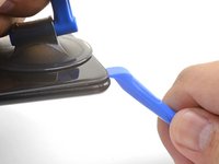
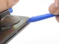
Once the opening tool's edge is wedged in position, carefully slide the tool along the bottom edge of the phone.
-
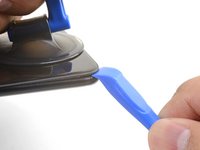
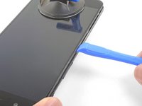
Carefully guide the opening tool around the left corner of the phone while keeping the tool's edge within the seam.
This was extremely difficult & took a lot of force. I needed a thin flat metal spudger and wrecked a couple of plastic ones in the process. I left a few scratches along the join in the process. It would be easier if I had something to hold the phone, in my hand I kept turning it on by accident.
what was the metal spudger did you use? I am having trouble as well. I cannot seem to pry the back cover and it feels like it is shut tightly, there are no crevices I can pry into. What was your strategy may I ask?
At first, I slightly opened the body with a plastic tool, but it was not enough to actually open the back cover. Then I used a thin metal screwdriver for this. It was difficult but nothing special. Just be sure that you are opening the correct seam between the body and the screen and don’t make sudden moves. I bent nothing, everything came back in place when reassembled.
ivan -
Same as David here: the plastic opening tools/guitar picks were doing nothing (not even creating the first "crack") . In the end I managed to open it using Jimmy (the metal knife/spudger), but not without scratching the whole metal cover.
-
-
-
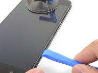
Lever the opening tool to release the first clip from the frame.
-
-
-
Continue sliding the opening tool along the long edge, releasing the clips along the way.
If you have difficulties with the last clip on the upper left. Try to go round the other side (right side), beginning at the bottom. This worked very well for me after having some difficulties with the clip near the front camera.
This helped me a lot as well. Couldn't get the upper left clip, but after going all the way around to the top right as well (keeping left clips released of course), it was pretty easy. Thanks, Sebastian!
-
-
-
With the bottom and left edge of the phone freed, gently wiggle the frame to release the top and right edge clips.
-
Align the top edge of the frame to the back cover and ensure that the top clips slip into place.
-
Squeeze along the long edges of the phone to snap the remaining clips into place.
Reinstalling the back cover stumped me for a second… If you’re struggling with aligning the top edge of the frame, remember that the camera is going to look off/pointed a bit too low until you actually clip the frame back in.
Really stupid but it was the only thing that tripped me up in this guide.
-
-
-
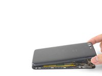
With all the clips released, flip the phone over so that the display is face-down.
-
Swing the back cover around and rest it on top of the exposed frame.
-
-
-
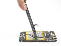
Remove the 2.6 mm Phillips screw holding the cable bracket above the battery in place.
-
Lift up and remove the cable bracket.
-
-
-
Use the point of a spudger to pry up and disconnect the back cover flex cable from its socket.
If it is damaged permanently is there a solution for it?
If the flex cable pins are damaged, the flex cable can be replaced.
If the connecter pins (on the motherboard) are damaged, you might need to do microsoldering (or contact a microsoldering company) to replace the damaged connector.
Brendan -
-
-
-
Use the point of a spudger to pry up and disconnect the battery connector from its socket.
-
-
-
Remove the six 2.6 mm Phillips screws securing the loudspeaker to the frame.
-
-
-
Insert the flat end of a spudger into the corner of the loudspeaker assembly and pry slightly, loosening the loudspeaker from its recess.
-
-
-
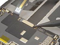
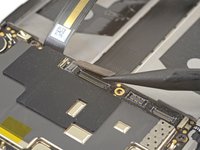
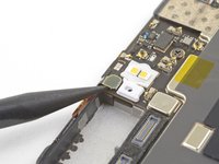
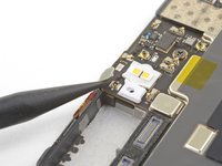
Use the point of a spudger to pry up and disconnect the interconnect flex cable from the socket.
What if you’re NOT replacing the battery?
This step is used in multiple guides, and not all of them require the cable to be bent away. You can just leave it sitting there, disconnected.
This image seems to show the daughterboard removed but there is no corresponding previous step. I see no way to remove the interconnect flex cable without removing the daughterboard. Possibly the volume switch can be removed with the cable still connected but I'm not confident enough to try this so will remove the daughterboard.
David,
Thanks for bringing this up. That's indeed a procedural error! I've added the missing steps in the affected guides.
-
-
-
-
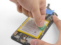
Peel the green pull tab up from the battery.
-
-
-
Brace the phone frame against the table.
-
Using a strong, steady force, pull the green pull tab upwards until the battery loosens from its recess.
-
Swing the battery completely out of its recess and pull it off of the plastic liner.
-
-
-
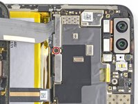
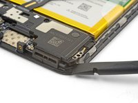
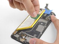
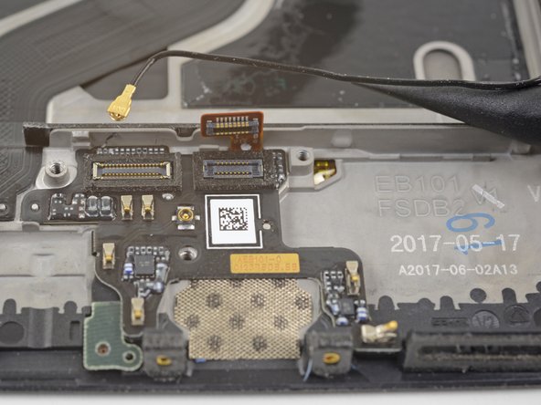
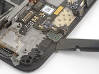
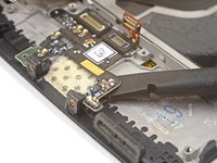
Use the point of a spudger the pry up and disconnect the fingerprint scanner connector from its socket on the daughterboard.
-
-
-
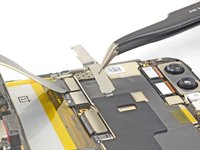
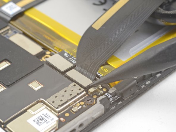
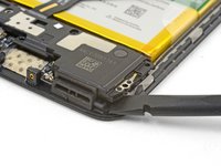
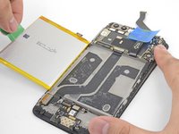
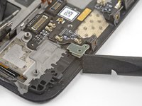
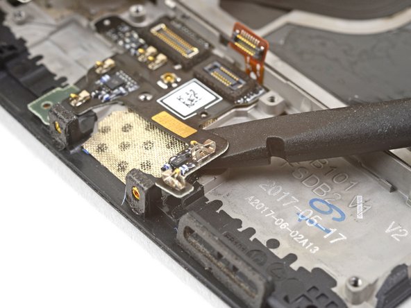
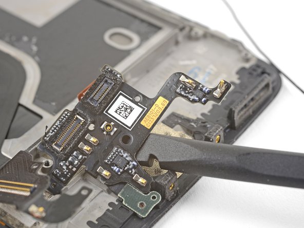
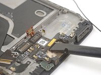
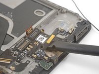
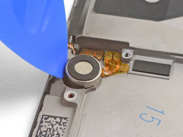
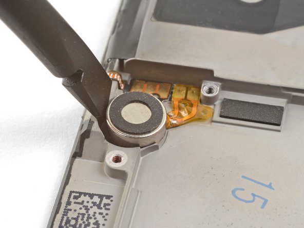
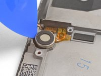
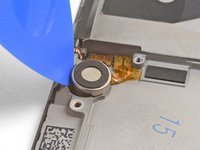
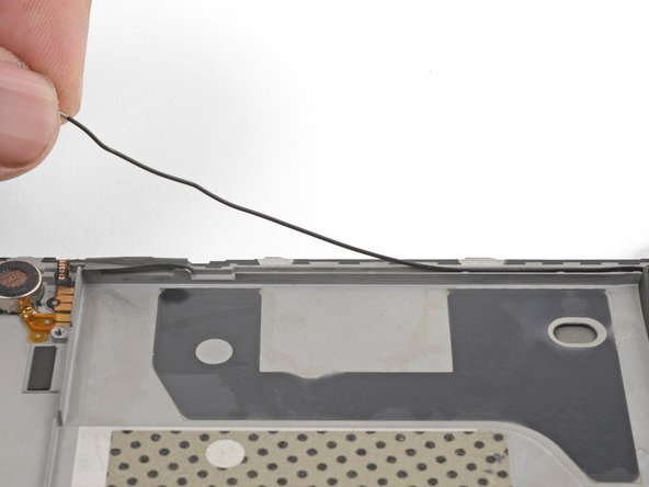
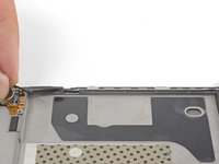
Slip the point of a spudger underneath the antenna interconnect cable and pry up to disconnect it from its socket on the daughterboard.
-
De-route the antenna interconnect cable out of the way of the daughterboard.
-
-
-
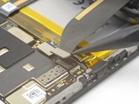
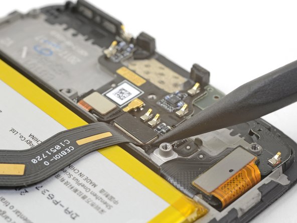
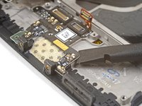
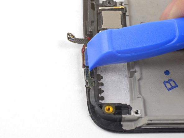
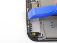
Insert the edge of a flat end of the spudger underneath the microphone board and twist slightly to release the board's adhesive.
-
-
-
Slide the flat end of a spudger or the point of an opening pick underneath the daughterboard near its right edge.
-
Gently pry to loosen the daughterboard from its recess.
-
-
-
Insert the flat end of a spudger underneath the daughterboard, this time approaching it from the bottom.
-
Twist and slide the spudger slightly to release the daughterboard from its recess.
-
-
crwdns2935267:0crwdne2935267:0Electrical Tape in 6 Assorted Colors$9.99
-
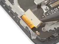
Slide the flat end of a spudger underneath the tape covering the fingerprint scanner.
-
Lift up to pry and remove the tape.
Hello! Does this silicone tape have the same thickness as the mesh that will be removed during disassembly? Do you have a mesh like that available or do you know a place to purchase it online?? Thanks
-
-
-
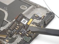
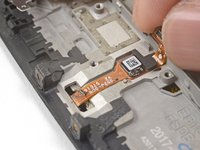
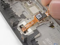
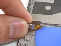
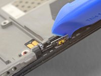
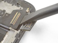
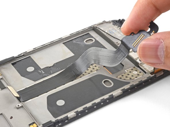
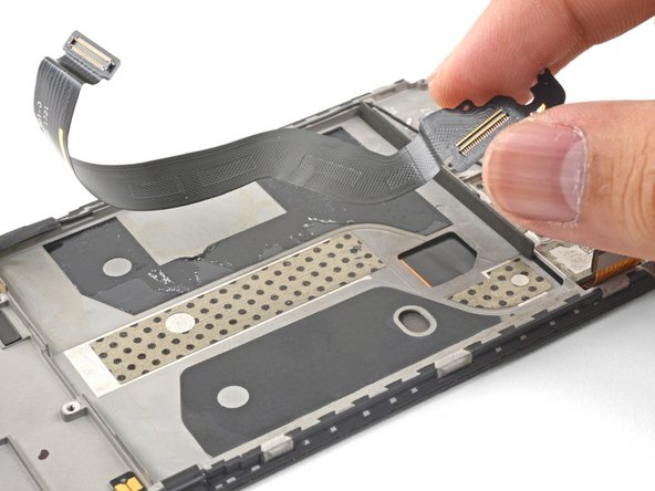
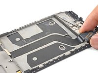
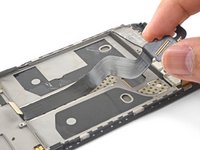
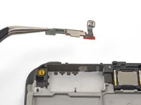
Use your finger to gently lift up the connector end of the fingerprint scanner. Pull upwards slowly. Do not pull directly away from the fingerprint scanner.
-
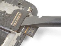
Keep pulling upwards until the fingerprint scanner cable is freed from its recess.
I couldn’t release this by pulling upwards as shown. Maybe I wasn’t brave enough & could have pulled harder. I used a fine pointed end of a scalpel blade under the left side where the QR code is & that, while pulling gently, did the trick.
-
-
-
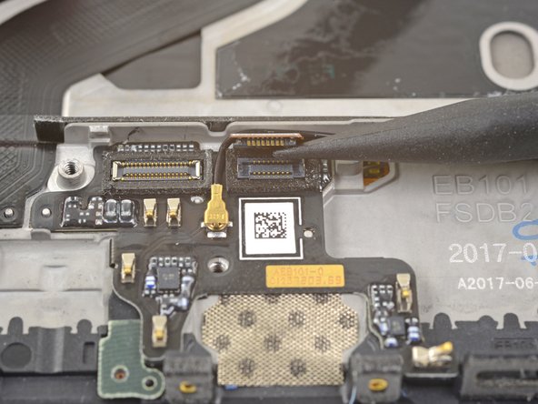
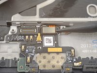
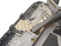
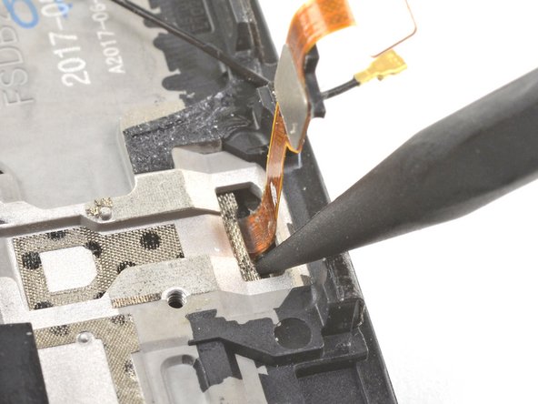
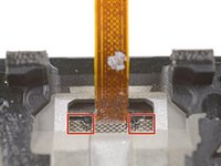
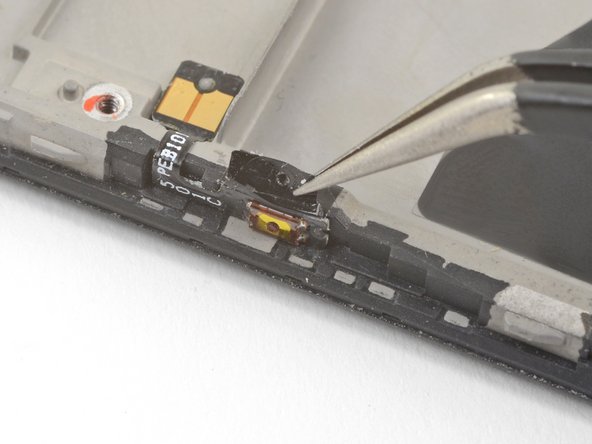
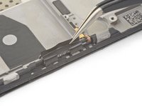
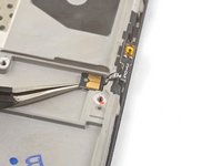
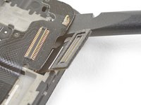
Insert the point of a spudger into the marked areas on either side of the flex cable, and push until the fingerprint scanner is loosened from its recess.
-
-
-
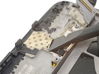
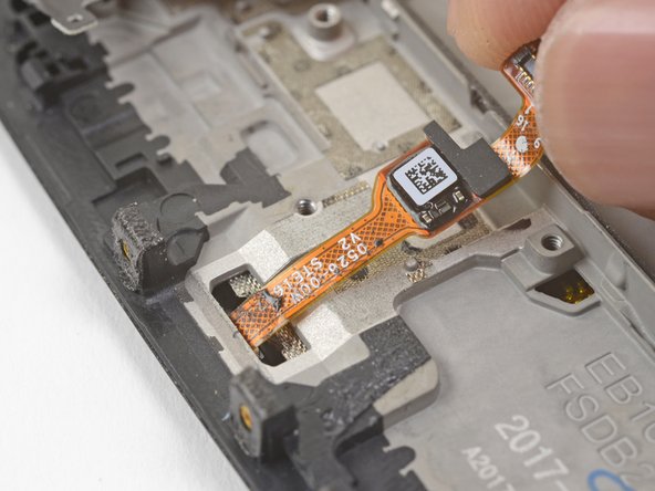
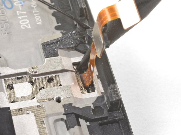
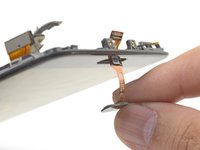
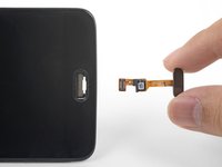
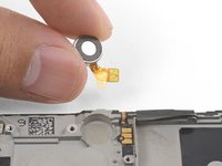
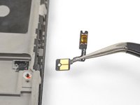
Once the fingerprint scanner is loosened from its recess, carefully thread its flex cable through the cutout, out of the front of the display.
-
Remove the fingerprint scanner.
My replacement fingerprint scanner did not come with any adhesive to hold it in place and it floated above the surface of the phone. I used a tiny amount of very carefully applied Gorilla contact adhesive which worked but will be a pain to remove next time.
-
-
-
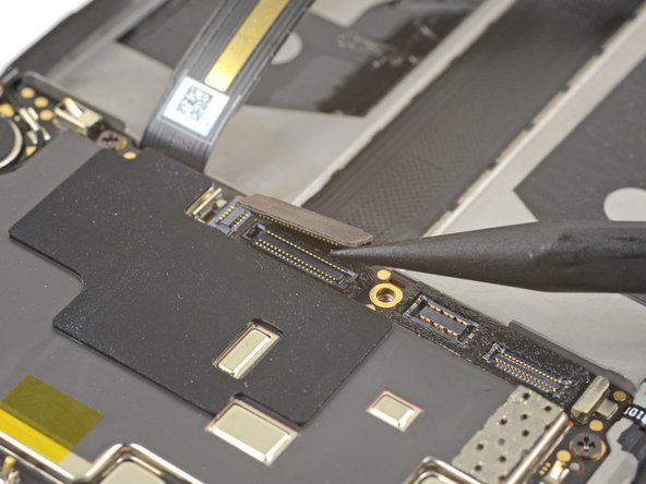
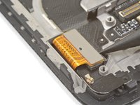
Use the point of a spudger to pry up and disconnect the display interconnect cable from its socket near the bottom edge of the motherboard.
Hallo, hier scheint der Schritt zu fehlen, in dem das Kameramodul entfernt wird.
Hello Norman,
You do not need to remove the camera module for procedure.
Hi Arthur,
You do need to remove the camera module, it’s in the photographs above, but not from step 33 onwards. It needs removing in order to remove the motherboard in steps 34 and 35.
Hi Alex! Thanks for the feedback! Can you relay which replacement guide you found the missing steps in? That would help me very much!
There are no steps 33, 34, 35 in this guide so the above comments must be from some other guide. With this phone I just lifted out the motherboard, carrying the camera with it. It went back the same way - but be careful not to trap the connector cable at the front under it.
-
-
-
Slide the point of a spudger underneath the antenna interconnect cable that is connected to the motherboard above the vibration motor.
-
Pry up to disconnect the cable from its socket.
-
De-route the cable out of its motherboard grounding clip and move it out of the way.
Be attentive when reassembling if your unit doesn’t have a tape, which keeps antenna interconnect cable in place — I’ve accidentally got it squeezed with back cover.
-
-
-
Slide the point of a spudger under the small square antenna connector connected to the motherboard near the top edge.
-
Pry up to disconnect the antenna connector from its socket.
camera step seem to be missing
The cameras should be removed in step 14.
-
-
-
Remove the following seven 2.6 mm Phillips screws securing the motherboard:
-
-
-
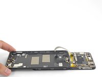
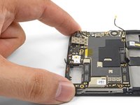
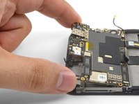
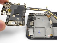
Use your fingers to lift up the top edge of the motherboard.
-
Lift the motherboard out of its recess and remove it.
The camera lens did not come up with the board.
Yup the cable with connector is glued to the frame. I removed the tape attaching the camera to the board, then removed the camera connector by gently pushing from the side. It does not seem to be glued.
Jason -
The previous steps have not removed the camera although the pictures show it has been removed. I found that I could carefully lift away the motherboard with the camera attached.
When replacing the motherboard take care not to trap the small square antenna connector under the top edge.
-
-
-
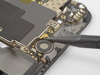
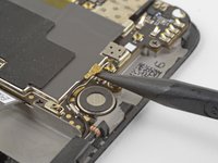
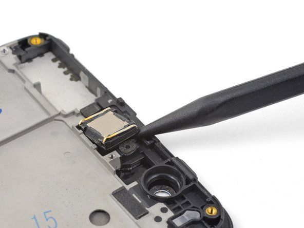
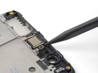
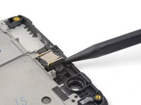
Insert the point of a spudger under the top right corner of the earpiece module and pry up, loosening the module from its recess.
-
-
-
Wedge the point of an opening pick between the vibration motor and the frame and push downward to loosen the vibration motor from its recess.
-
Once the vibration motor is slightly loosened, you can wedge the flat end of a spudger between the motor and the frame to help free it from its recess.
-
-
-
Slide the point of an opening pick underneath the vibration motor's flex pad and gently pry it off of the frame.
-
Remove the vibration motor.
The pads were stuck to the frame. The pads eventually broke off the cable. Be careful. Maybe use a heatgun or hairdryer to loosed the adhesive.
I found it easier to do the next step first. Without the volume connectors, this gave me a better angle to get the motor connectors off the adhesive.
-
-
crwdns2935267:0crwdne2935267:0Electrical Tape in 6 Assorted Colors$9.99
-
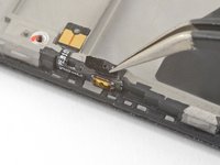
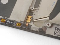
Use tweezers or the point of a spudger to pry up and remove the black tape covering the volume buttons on the right edge of the phone.
-
Repeat the process with the black tape covering the power button on the left edge of the phone.
-
-
-
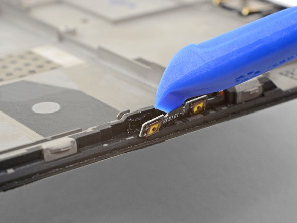
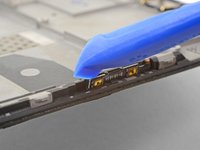
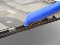
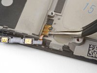
Use the edge of an opening tool to gently pry the volume button board away from the frame.
-
Continue prying until you loosen the volume button board from the frame.
-
-
crwdns2935267:0crwdne2935267:0Tesa 61395 Tape$5.99
-
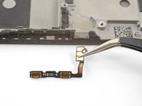
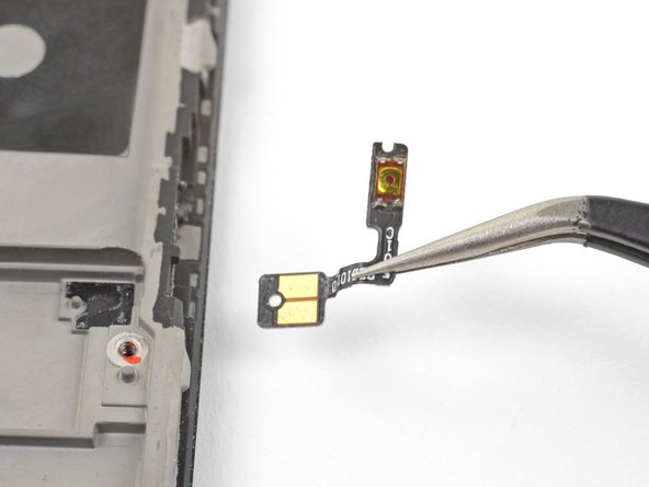
Squeeze the tweezer tips together and insert the point underneath the volume button board's contact pad near the top right edge of the frame.
-
Pry upwards to loosen the contact pad from the frame.
-
Remove the volume buttons.
Installing a vol button to a used frame I found the existing adhesive (a black sticky rubbery compound) still sticky enough to hold all in place except for the last 2mm of the outer strip with the switches which I fixed with a tiny piece of double sided tape. The tape was not at all adhesive & it's not obvious what it's for. Electric tape doesn't stick to the vol button strip so I used 2 or 3 pin prick size dots of contact adhesive to keep it in place. Fingers crossed!
This is the only step which mentions using a used board and tesa tape. Is it possible to use tape in the other places adhesive is used?
-
-
-
Repeat the previous two steps to remove the power button from the left edge of the frame.
-
-
-
Peel and remove the plastic battery liner from the frame.
-
-
-
Use the point of a spudger to pry up the display connector from its socket near the bottom left corner of the frame.
-
-
-
Insert the flat end of a spudger underneath the display interconnect cable socket, near where it connected with the display connector in the bottom left corner of the frame.
-
Pry upwards and slide the spudger underneath the cable to loosen the cable from the frame.
-
-
-
Grasp the loosened end of the display interconnect cable with your fingers and pull upwards, releasing the cable from the frame.
-
Remove the display interconnect cable.
-
-
-
Use your fingers to lift and de-route the antenna interconnect cable from its groove on the right edge of the frame.
-
Transfer the antenna interconnect cable to the new frame.
-
-
-
Use the edge of an opening tool to push the back cover antenna connector away from the frame. It is located on the top edge of the frame.
-
Remove the back cover antenna connector.
-
If you are transferring the connector onto a replacement frame, peel the blue liner on the top edge of the replacement frame before sticking the connector onto the edge.
-
-
-
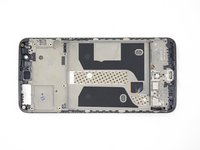
The bare screen and digitizer assembly remains.
-
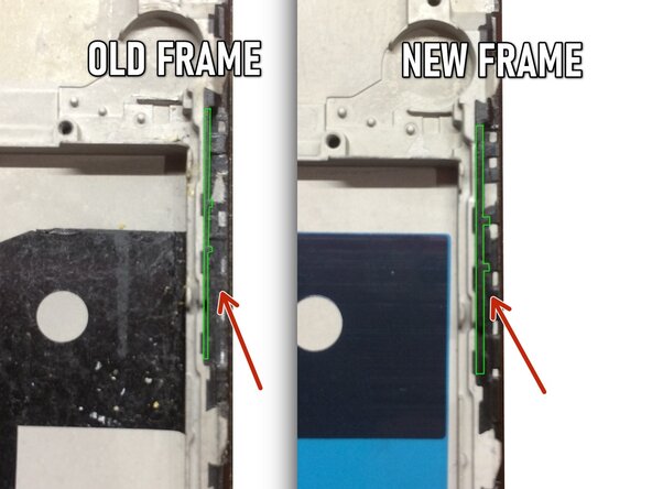
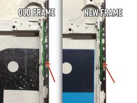
Transfer all of the parts you removed in the previous steps from the old assembly to the new one.
Pay attention to the side where the volume buttons should be located!
The thickness of the border from the battery compartment to the volume buttons may differ between the previous and new screen frame.
In my case, my previous screen frame was thinner, which is why the volume buttons were always pinched when the smartphone was fully assembled!
I had to be very careful to adjust the thickness with a clerical knife, scraping the black plastic where the two buttons are physically located (be careful, there is a risk of breaking off the clamps).
However, there is no need to scrape the side where the “Power” button is located. At least, I didn't have to do it. -


To reassemble your device, follow these instructions in reverse order.
Take your e-waste to an R2 or e-Stewards certified recycler.
Repair didn’t go as planned? Check out our OnePlus 5 Answers Community for troubleshooting help.
To reassemble your device, follow these instructions in reverse order.
Take your e-waste to an R2 or e-Stewards certified recycler.
Repair didn’t go as planned? Check out our OnePlus 5 Answers Community for troubleshooting help.
crwdns2935221:0crwdne2935221:0
crwdns2935229:033crwdne2935229:0

crwdns2947412:018crwdne2947412:0
Nice. But where do you get the replacement part from?
Dear Christos, hope it is not too late, you can check Oneplus 5 screen replacement from Witrigs
HI . Do I need to buy an original screen and digitizer for my oneplus 5?
I'm from Argentina and on EBAY I do not see ORIGINAL parts
Can someone help me?
Hi Joselo,
You do not need an original, but that is probably the best quality. The original screen is AMOLED. There are also OLED and LCD replacement screens. These will not be as bright as the original AMOLED panel.
Hi, I need to know if this screen is like the original (Amoled) or not, and approximately how long it takes to send by mail to Miami Florida. Thank you OnePlus 5 Screen
Hi Joselo, that Screen and Digitizer Assembly is indeed an AMOLED screen and digitizer.
As for the shipping question: In order to determine shipping estimates, costs, and methods, you will need to enter your shipping address at checkout as this may vary based on the specific address.
If you ever have any questions, feel free to contact our iFixit Customer Support. We are always here to assist if you need anything. :)
Wow, this repair looks hard. I’d rather buy a new phone than attempt this.
Don’t blame you; the time commitment is hard to justify. However, I had a few hours to spare and took it slow: now I have a backup device from a (my first) phone repair :)
manual is very clear, successfully replaced the screen this weekend. difficulty is not too bad
DO NOT TRY TO OPEN THE PHONE. Its a !&&* to repair this phone yourself. I opened it and could not epair this phone. Everything is glued and the buttonconnectors are not designed to be replaceble.
CAUTION and do not repair.
Thanks for the guide, made me able to change my own screen for real cheap!
U forgot the front camera :)
Otherwise great guide!
The contacts for the vibration motor were hard to get off!
I left the front camera attached to the motherboard when I removed the board, but you can remove it separately.
The vibration contacts are pretty heavily glued in! They have to—otherwise, the motor will shake loose :)
Just used this guide, managed to get all the parts off my old phone but have noticed on the new frame there is not any black sticky for the parts to stick onto, it's just bare metal where they're supposed to adhere. Can anyone enlighten me?? Can I buy this double sided black tape? Is Tesa tape a good replacement? I'm assuming things will short out if I try to stick them into the bare metal frame?
Hi Rich,
Tesa tape is a good option! Depending on what you are sticking, you may only need the Tesa adhesive card. For smaller parts such as the side buttons, double-sided tape will suffice.
Nice tutorial. Everything works now after switching the screen. Took about 3h to someone with experience, but the steps are well documented.
The screen replacement from ifixit is not the same quality as the original (particularly the glass is very fragile); still, it's very nice to have access to spare parts and avoid buying a whole new phone!
Solid guide! Pretty intensive repair; only difficulty was to get a new piece of electrical tape to cover the buttons: ended up neglecting to replace that and just using them as is (with greater sensitivity).
my phone is lcd cant touch. what the problem? but lcd is some times on and off.