crwdns2915892:0crwdne2915892:0
Use this guide to replace the charging port assembly in your Nokia G42 5G.
Note: The Nokia G42 5G's charging port assembly is a daughterboard that includes both the USB-C charging port and the headphone jack.
crwdns2942213:0crwdne2942213:0
-
-
Power down your phone and unplug any cables.
-
Insert a SIM eject tool, bit, or a straightened paper clip into the small hole on the SIM card tray on the upper left edge of the phone.
-
Press firmly to eject the tray.
-
-
-
Remove the SIM card tray.
-
-
-
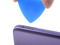
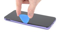
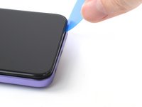
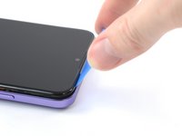
Insert an opening pick under the small notch in the SIM card tray slot.
With the phone flat, screen up, insert the pick into the slot horizontally, then rotate the pick to the upright position, as shown in the photo in step 4.
With the phone laying flat on its back, insert the pick into the slot horizontally, then flip the pick upright, as per photo in step 4.
Don't try to fully remove the back cover just yet, as it's still connected with a cable.
-
-
-
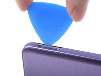
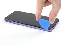
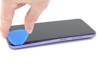
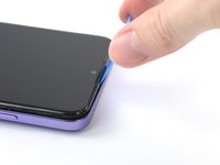
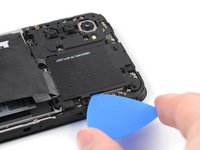
Position the opening pick at a steep downward angle between the back cover and the screen assembly.
-
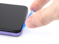
Slide the opening pick down the left edge of the phone to release the plastic clips.
-
-
-
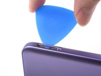
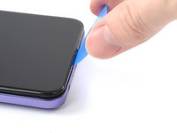
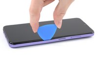
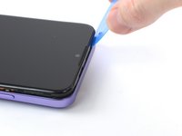
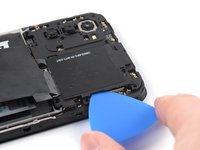
Turn the opening pick around the corner and continue to slide it along the bottom edge to release the plastic clips.
-
-
-
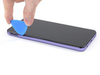
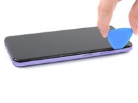
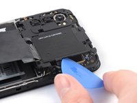
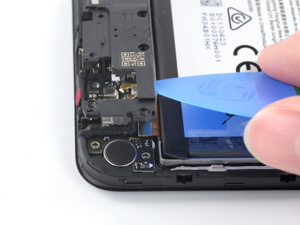
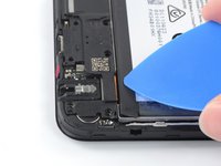
Slide the opening pick up the right edge to continue releasing the plastic clips.
Fingerprint-cable is easily broken. Careful around that button.
-
-
-
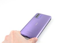
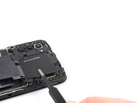
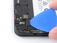
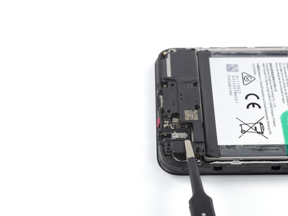
Slide the opening pick along the top edge to release the remaining plastic clips.
-
-
-
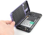
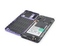
With the phone laying screen-side down, carefully lift the right edge of the back cover, opening it like a book.
-
Lay the back cover next to the phone.
Das ist nicht das Kabel für den Fingerabdrucksensor, sondern für den Ein-/Ausschalter und der Schalter hat sich bei mir gelöst und es hat mir einige Nerven gekostet das Maleur wieder zu beheben. Der Schalter ist nur sehr lose eingeclipst und muss dann zum Drehen und befestigen des Kabels am Motherboard mit dem Vorderteil gedreht werden.
-
-
-
-
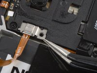
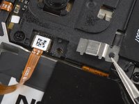
Use a Phillips screwdriver to remove the 3.8 mm‑long screw securing the fingerprint reader bracket.
-
-
crwdns2935267:0crwdne2935267:0Tweezers$4.99
-
Use a pair of tweezers or your fingers to remove the fingerprint reader bracket.
The metal fits under the black plastic near the screw shown to the left of the photo. When re-assembling, insert it back under here first, then lower the right-hand side back into place.
-
-
-
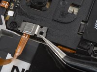
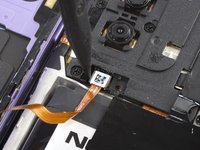
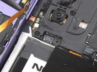
Use the pointed end of a spudger to disconnect the fingerprint reader by prying the connector straight up from its socket.
-
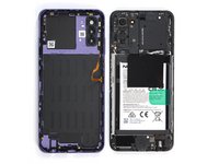
Remove the back cover.
-
-
-
Use a Phillips screwdriver to remove the ten 3.8 mm-long screws securing the motherboard cover.
There is a clip near the top left screw - when you re-assemble, pop this back into place first.
-
-
-
Insert an opening pick under the right edge of the motherboard cover.
-
Twist the opening pick to release the plastic clips.
-
-
-
Use a pair of tweezers or your fingers to remove the motherboard cover.
-
-
-
Use the flat end of a spudger to disconnect the battery cable by prying the connector straight up from its socket.
-
-
-
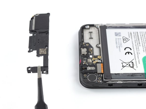
Use a Phillips screwdriver to remove the eight 3.8 mm-long screws securing the loudspeaker.
-
-
-
Insert an opening pick underneath the top right edge of the loudspeaker.
-
Twist the opening pick to release loudspeaker from the plastic clips holding it in place.
-
-
-
Use a pair of tweezers or your fingers to remove the loudspeaker.
-
-
-
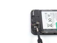
Use the flat end of a spudger to disconnect the interconnect cable by prying the connector straight up from its socket.
-
-
-
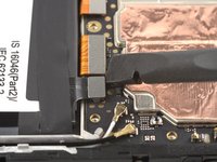
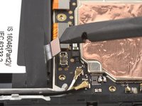
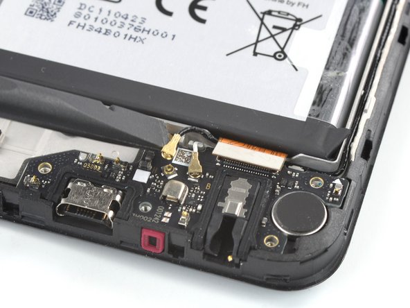
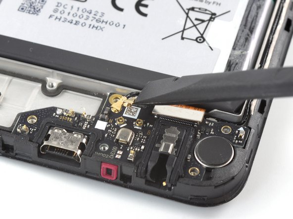
Use a spudger to disconnect the antenna cables by prying their coaxial connectors straight up from the sockets on the board.
-
-
crwdns2935267:0crwdne2935267:0Tweezers$4.99
-
Use a pair of tweezers or your fingers to grip the antenna cables near the connectors.
-
Reposition the antenna cables out of the way of the charging port assembly.
-
-
-
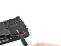
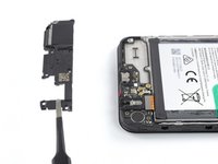
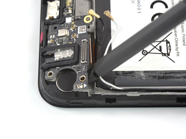
Insert the flat end of a spudger underneath the top right edge of the charging port assembly.
-
Pivot the charging port assembly up until you can grip it with your fingers.
-
-
-
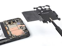
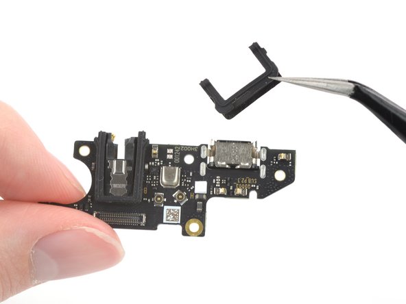
Use your fingers or a pair of tweezers to remove the charging port assembly.
-
-
-
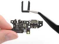
Use a pair of tweezers to remove the two black U-shaped rubber gaskets from the charging port and the headphone jack.
-
Only the charging port assembly remains.
-


To reassemble your device, follow these instructions in reverse order.
Take your e-waste to an R2 or e-Stewards certified recycler.
Repair didn’t go as planned? Try some basic troubleshooting, or ask our Answers community for help.
To reassemble your device, follow these instructions in reverse order.
Take your e-waste to an R2 or e-Stewards certified recycler.
Repair didn’t go as planned? Try some basic troubleshooting, or ask our Answers community for help.
crwdns2935221:0crwdne2935221:0
crwdns2935229:02crwdne2935229:0


crwdns2947412:02crwdne2947412:0
Success!If I can do it anyone can. How ever if I never have to reconnect antennae cables and finger print readers again it will be too soon.
Great! Took me a bit longer than expected (1h30) but I was delivered with sausages for fingers.