crwdns2915892:0crwdne2915892:0
Use this guide to replace a broken screen on your Nokia G310 5G.
This guide is written for the genuine Nokia G310 5G screen assembly. The assembly consists of the screen and midframe together as one part. Make sure you have the correct part before you begin this repair.
Note: This procedure requires transferring your phone's internals into the new assembly.
For your safety, turn on your phone and allow the battery to discharge below 25% before starting this procedure. This reduces the risk of fire if the battery is accidentally damaged during the repair. If your battery looks puffy or swollen, take extra precautions.
crwdns2942213:0crwdne2942213:0
-
-
Power down your phone and unplug any cables.
-
Insert a SIM eject tool, bit, or a straightened paper clip into the small hole on the SIM card tray on the upper left edge of the phone.
-
Press firmly to eject the tray.
-
-
-
Remove the SIM card tray.
-
-
-
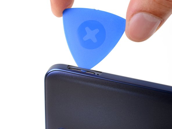
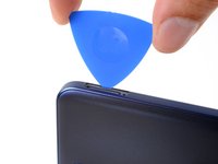
Insert an opening pick under the small notch in the SIM card tray slot.
-
-
-
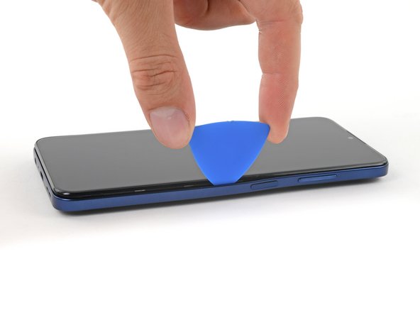
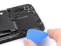
Position the opening pick at a steep downward angle between the back cover and the screen assembly.
-
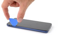
Slide the opening pick down the left edge of the phone to release the plastic clips.
-
-
-
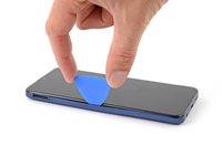
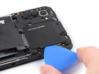
Turn the opening pick around the corner and continue to slide it along the bottom edge to release the plastic clips.
-
-
-
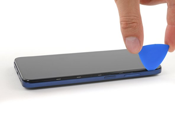
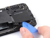
Slide the opening pick up the right edge to continue releasing the plastic clips.
-
-
-
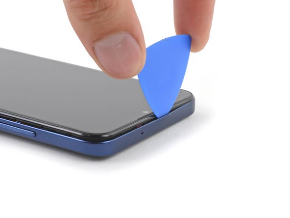
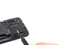
Slide the opening pick along the top edge to release the remaining plastic clips.
-
-
-
With the phone laying screen-side down, carefully lift the right edge of the back cover, opening it like a book.
-
Lay the back cover next to the phone.
-
-
-
Use a Phillips screwdriver to remove the 3.8 mm‑long screw securing the fingerprint reader bracket.
-
-
crwdns2935267:0crwdne2935267:0Tweezers$4.99
-
Use a pair of tweezers or your fingers to remove the fingerprint reader bracket.
-
-
-
Use the pointed end of a spudger to disconnect the fingerprint reader by prying the connector straight up from its socket.
-
Remove the back cover.
-
-
-
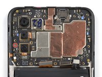
Use a Phillips screwdriver to remove the ten 3.8 mm-long screws securing the motherboard cover.
There is a clip near the top left screw - when you re-assemble, pop this back into place first.
-
-
-
Insert an opening pick under the right edge of the motherboard cover.
-
Twist the opening pick to release the plastic clips.
-
-
-
-
Use a pair of tweezers or your fingers to remove the motherboard cover.
-
-
-
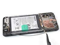
Use the flat end of a spudger to disconnect the battery cable by prying the connector straight up from its socket.
-
-
-
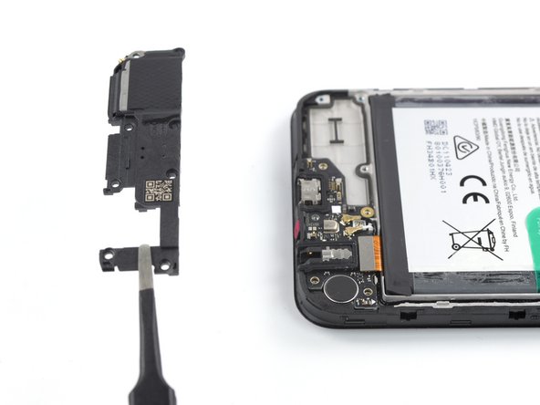
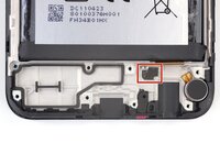
Use a Phillips screwdriver to remove the eight 3.8 mm-long screws securing the loudspeaker.
-
-
-
Insert an opening pick underneath the top right edge of the loudspeaker.
-
Twist the opening pick to release loudspeaker from the plastic clips holding it in place.
-
-
-
Use a pair of tweezers or your fingers to remove the loudspeaker.
-
-
-
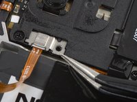
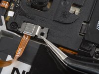
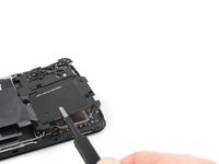
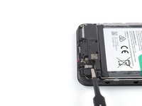
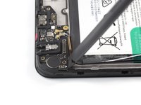
Use the flat end of a spudger to disconnect the interconnect cable by prying the connector straight up from its socket.
Hello there, I have damaged the interconnect cable during the screen replacement process, do you offer replacement cables for sale?
Hello Oliver, unfortunately we currently do not have interconnect replacement cables available in the iFixit store. In this case, please reach out to Nokia Phones support!
-
-
-
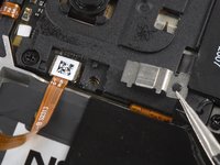
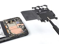
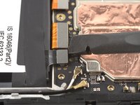
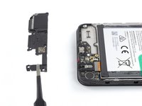
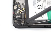
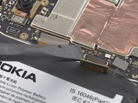
Use a spudger to disconnect both antenna cables by prying their connectors straight up from the sockets on the motherboard.
-
-
crwdns2935267:0crwdne2935267:0Tweezers$4.99
-
Use a pair of tweezers or your fingers to lift the antenna cables out of their recess in the frame.
-
-
-
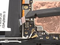
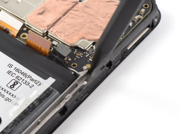
The top edge of the charging port assembly is held in place with adhesive.
-
Insert the flat end of a spudger underneath the top right edge of the charging port assembly.
-
Pivot the charging port assembly up until you can grip it with your fingers.
-
-
-
Use a pair of tweezers or your fingers to remove the charging port assembly.
Seemed to help to also pry the board up from the end by the screw hole near the antenna cables. Then it popped out.
CAUTION ther is a tiny sticky pad underneath this board that the guide does not knowledge which resulted in unexpected resistance and subsequently BROKE this board for me. PLEASE BE CAREFUL.
iTS RIGHT NEXT TO THE INTERCONNECT CABLE
Hi Adam,
I'm sorry about hearing the issue you had during your repair. The adhesive you mention is being acknowledged in the previous step, see the first bullet point: "The charging port assembly is held in place with mild adhesive". Based on your feedback, I feel like this could be pointed out even more clearly, so thank you for your input.
-
-
crwdns2935267:0crwdne2935267:0Tesa 61395 Tape$5.99
-
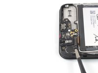
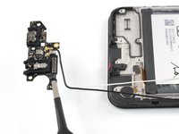
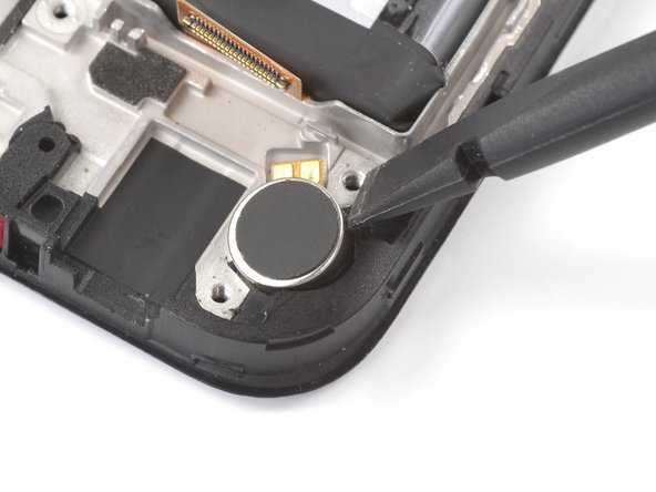
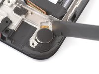
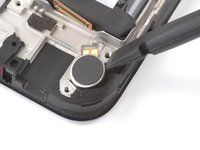
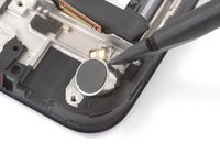
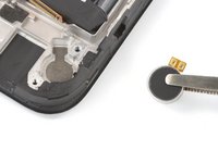
Insert the flat end of a spudger into the small recess on the upper right side of the vibration motor.
-
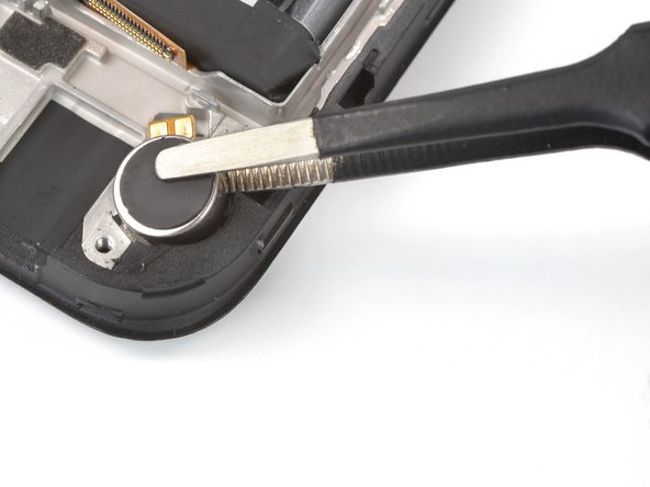
Pivot the spudger up to pry up the vibration motor off of the adhesive securing it underneath.
I could not insert the flat end of the spudger into the small recess to remove the vibration motor. In the end I used a very small flat screwdriver to lift it up.
I used some sturdy tweezers to pull it up, you could also use needle-nosed pliers. As Gijsbert said, prying does not work.
J'ai du utiliser une lame fine la spatule ne rentre pas
-
-
-
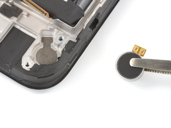
Use a pair of tweezers or your fingers to remove the vibration motor.
-
-
-
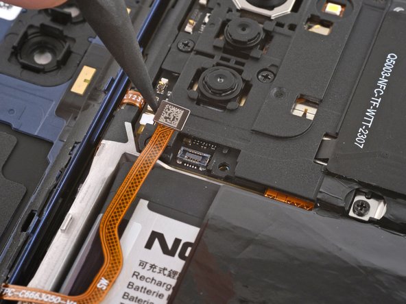
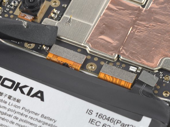
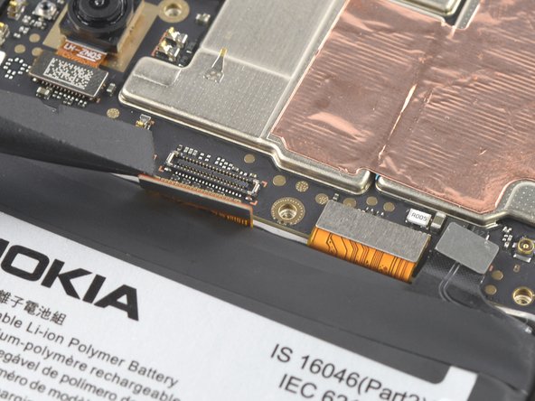
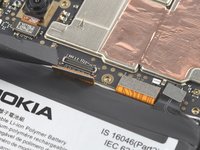
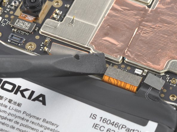
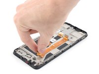
Use the flat end of a spudger to disconnect the display cable by prying the connector straight up from its socket.
Upon re-assembly the display cable of the new assembly was somewhat longer than the old assembly, I could not reconnect it because there was a little bit too much strain on the cable while bending it. I had to remove the battery again (fortunately I had not applied pressure yet to glue it in place), so I recommend to install the battery after attaching the display cable.
-
-
-
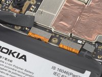
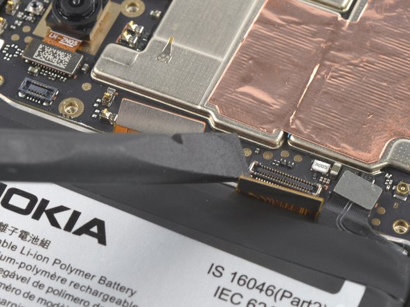
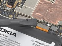
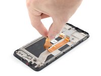
Use the flat end of a spudger to disconnect the interconnect cable by prying the connector straight up from its socket.
-
-
-
Use a Phillips screwdriver to remove the single 2.8 mm‑long screw securing the motherboard.
2.5 mm-long screw instead of 2.8 mm-long screw.
please do not use red circles when the board is green. I actually missed the screw almost.
-
-
-
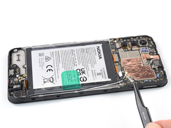
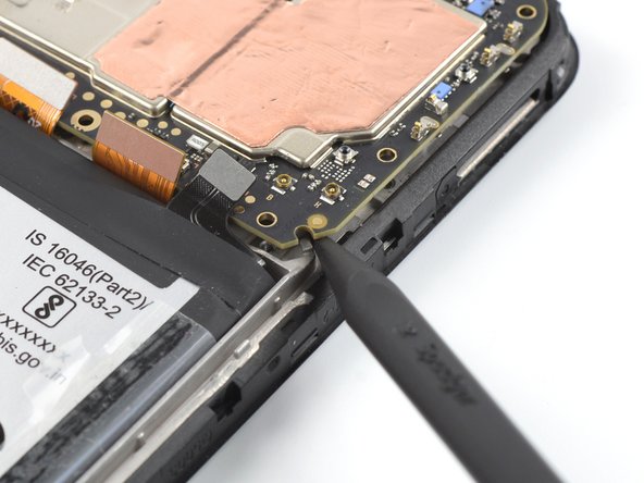
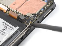
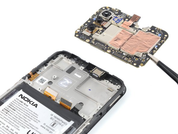
Insert the pointed end of a spudger underneath the bottom right corner of the motherboard.
-
Pry the motherboard up until you can grip it with your fingers.
There is a clip near the top right screw that the motherboard fits under. When re-assembling, make sure you fit this corner in under the clip first, or the motherboard sits on top of it and the screw ill not engage with the threads in the hole - the motherboard will sit proud by about 1mm.
-
-
-
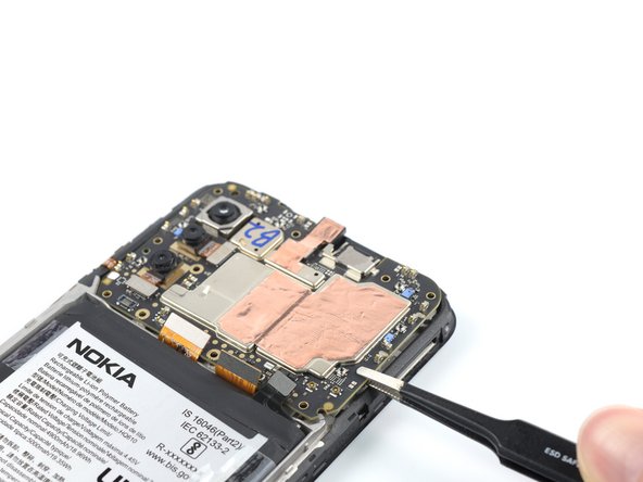
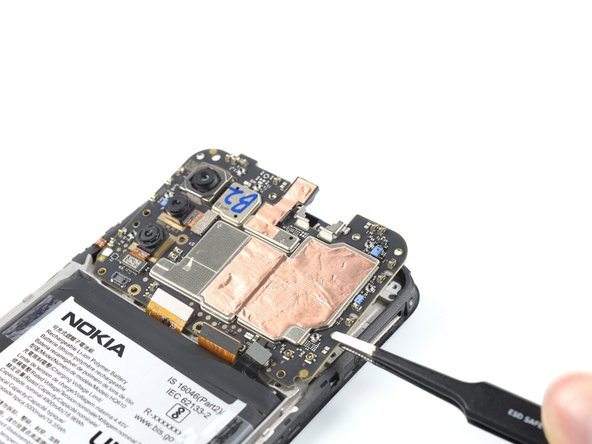
Grip the motherboard on the right edge using a pair of tweezers or your fingers.
-
Remove the motherboard.
-
-
-
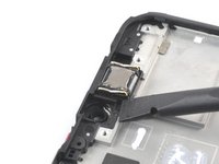
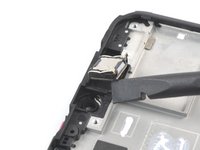
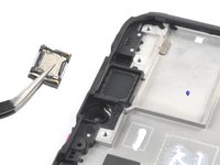
Insert the flat end of a spudger underneath the bottom left corner of the earpiece speaker and pry it out of its recess.
-
Remove the earpiece speaker.
-
-
-
Use your fingers to peel the two outer adhesive tabs off of the battery.
Please see also step 26: Upon re-assembly the display cable of the new assembly was somewhat longer than the old assembly, I could not reconnect it because there was a little bit too much strain on the cable while bending it. I had to remove the battery again (fortunately I had not applied pressure yet to glue it in place), so I recommend to re-install the battery after attaching the display cable.
-
-
-
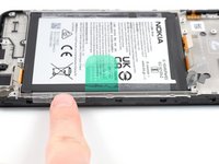
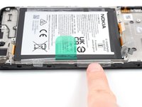
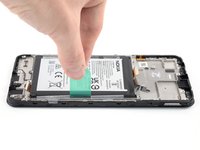
Use your fingers to peel the center green pull tab off of the battery.
-
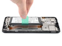
Using one hand to hold the phone steady, use your other hand to slowly and steadily lift the center green pull tab up to separate the adhesive securing the battery underneath.
-
If you have any difficulties with stubborn battery adhesive, you can contact Nokia's phones support.
-
-
-
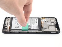
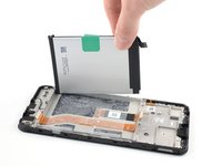
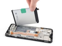
Peel the battery off of the adhesive film and remove it.
-
-
-
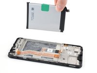
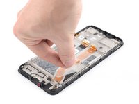
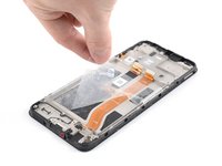
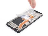
Grab the bottom right edge of the leftover adhesive film and pull it towards the top of the phone with steady force to remove it.
-
Remove the battery adhesive film from its liners and apply it to the battery.
-
Align the bottom edge of the battery (the edge without adhesive) with the bottom edge of the recess.
-
Lower the battery down and press firmly to secure it in place.
-
-
-
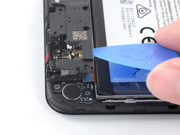
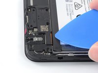
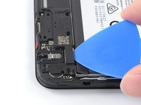
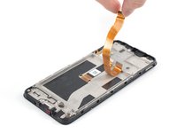
Grab the bottom of the interconnect cable and peel it up towards the top of the phone to remove it.
Please see also step 26: re-install the battery after you have reconnected the interconnect cable to the motherboard.
-
-
-
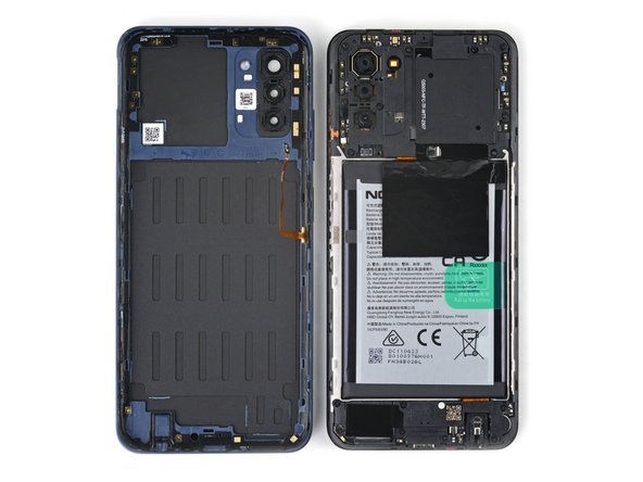
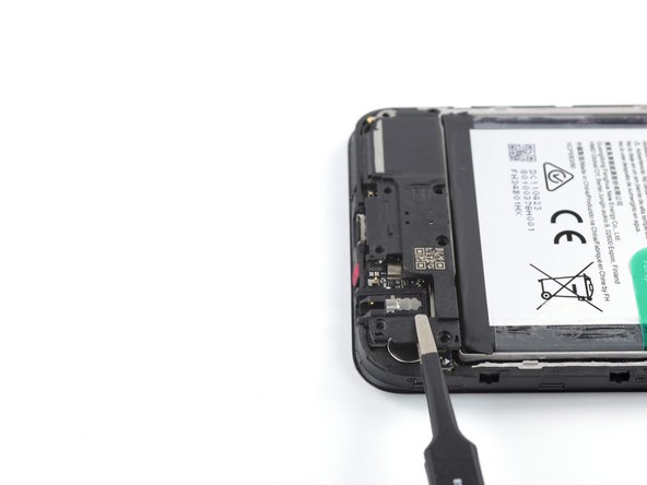
Only the screen assembly remains.
-
If your part comes with battery adhesive pre-installed, remove its plastic liners before continuing to the previous step.
-
If your part has no battery adhesive, remove the clear liner on the pre-cut battery adhesive and apply the sticky section to the battery well. Remove the opaque liner before continuing to the previous step.
After replacing the screen myself, the phone stopped receiving the network. I had to throw it away and buy a new phone. Waste of money for screen
Hello Igor, sorry to hear that you experienced issues following your repair. It sounds like the issue might have been caused by the antenna cable being damaged or disconnected. In these cases, we recommend physically reseating the connectors of the antenna cable on both motherboard and daughterboard as well as checking the cable and connectors for signs of damage. If this doesn't help, you can contact Nokia's phones support to get further support.
This worked like a charm! It wasn’t too frustrating and my phone is as good as new!
how can i remove the assemble, i broke my screen and cant find a guide on how to remove and replace the screen
Hi there! The replacement part in this case is the screen assembly, so not just the screen but the midframe and buttons. Therefore, the repair consists in moving the components to the new screen assembly without removing / replacing the screen itself. Hope this helps!
I ordered a screen + frame kit off Amazon but the new frame does not come with the power and volume buttons connector attached. Your guide does not show how to remove this part from the old frame and place it on a new one. Is this possible or should I buy a screen-only kit and attempt to attach it to the old frame?
Hi Daniel! The genuine replacement part available in the iFixit Store should include pre-installed buttons. Transferring the buttons is pretty finnicky and not generally recommended, but definitely possible. The buttons are held in place by adhesive that can potentially be reused for the new frame. Doing a screen-only repair would require a different procedure and application of heat and suction to remove the old screen.
Indeed, had the same issue. The buttons are mildly glued, so you can gently pull them off. Used a needle for it, there are small indents you can use.
jos -
Controleer of er ook een Power en volume knop flex kabel op (de zijkant) zit! Want die zit niet altijd standaard op de nieuwe schermmodule.
-


To reassemble your device, follow these instructions in reverse order.
Take your e-waste to an R2 or e-Stewards certified recycler.
Repair didn’t go as planned? Try some basic troubleshooting, or ask our Answers community for help.
To reassemble your device, follow these instructions in reverse order.
Take your e-waste to an R2 or e-Stewards certified recycler.
Repair didn’t go as planned? Try some basic troubleshooting, or ask our Answers community for help.
crwdns2935221:0crwdne2935221:0
crwdns2935229:02crwdne2935229:0

crwdns2915084:0crwdne2915084:0

Guide Team crwdns2935289:0Guide Teamcrwdne2935289:0
Staff
crwdns2931471:09crwdne2931471:0
crwdns2935297:013,054crwdne2935297:0
crwdns2947412:02crwdne2947412:0
Where does the Touchscreen electrically connect to?
This is a great how to. Assembly and tool kits had everything needed. Photos were clear with plenty of supplemental photos and materials. Replacing AA batteries in a remote is about the max tech repair I have ever done. I bought the G310 with self repair in mind because I am clumsy, but I was intimidated by the actual task. Thank you so much for making this enormously thorough and clear guide so a total tech novice could do it.