crwdns2915892:0crwdne2915892:0
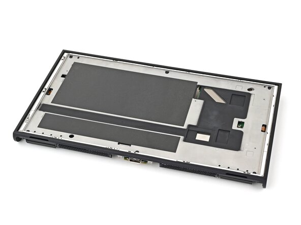
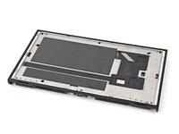
Follow this guide to replace a cracked or broken screen on a Nintendo Switch 2 game console.
The Switch 2 uses JIS screws. If you use a non-iFixit Phillips driver in JIS screws, you'll risk stripping them. iFixit's Phillips bits are designed to be compatible with JIS screws.
You’ll need new thermal putty and regular thermal paste to complete this repair.
crwdns2942213:0crwdne2942213:0
-
-
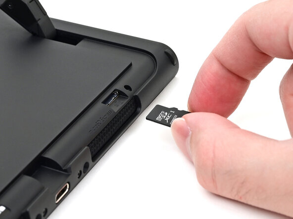
Remove any game cards and disconnect any cables, controllers, or other accessories from the console.
-
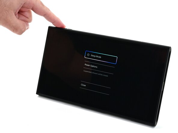
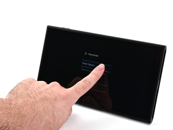
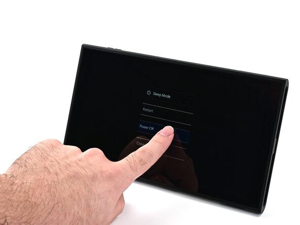
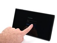
Power off the console by holding down the power button, selecting Power Options, then pressing Power Off.
-
-
-
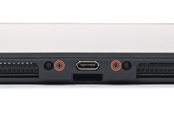
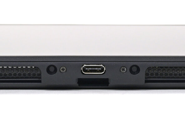
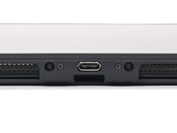
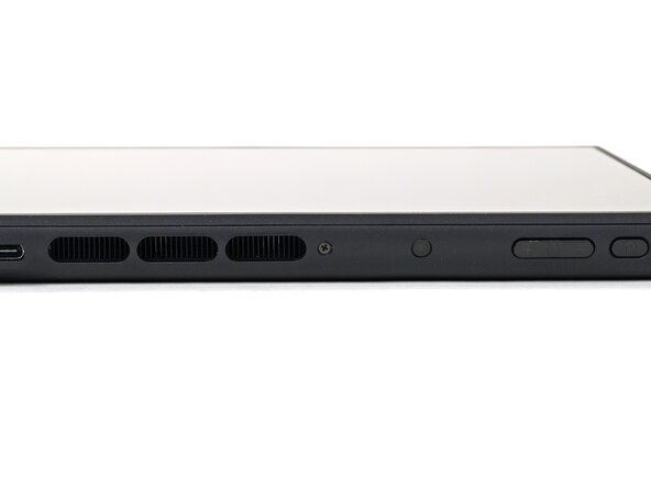
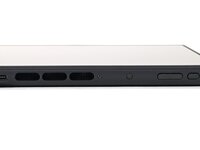
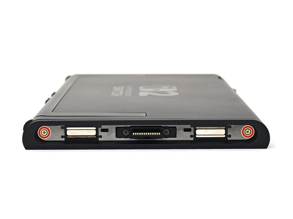
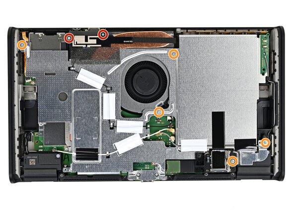
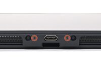
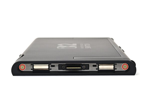
Use a JIS 00 driver to remove the two 3.1 mm‑long screws on either side of the bottom USB-C port.
-
-
-
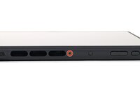
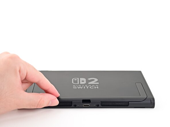
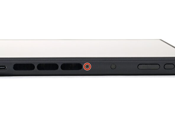
Use a JIS 00 driver to remove the 3.1 mm‑long screw on the top edge of the console (next to the ventilation cutouts).
-
-
-
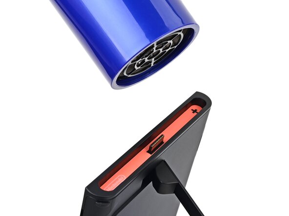
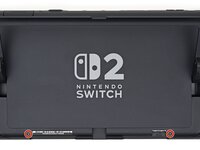
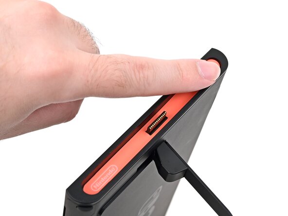
Use a hair dryer or heat gun to heat the sticker on the right side of the console, labeled with a "+" symbol, until it's hot to the touch.
-
-
-
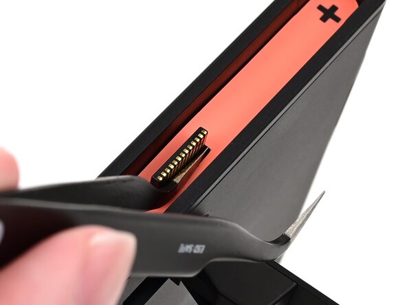
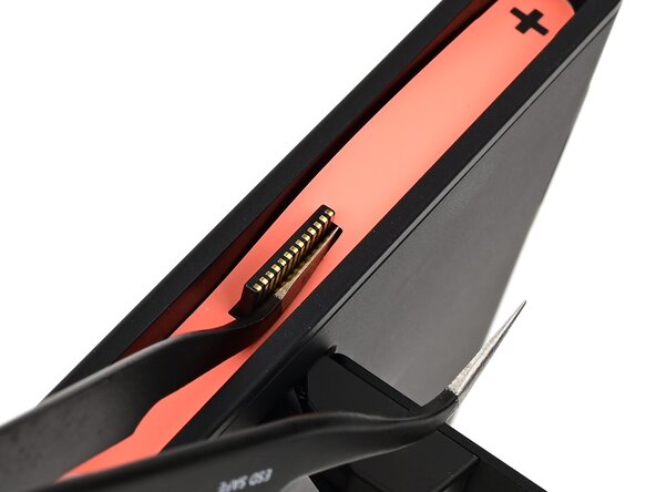
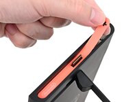
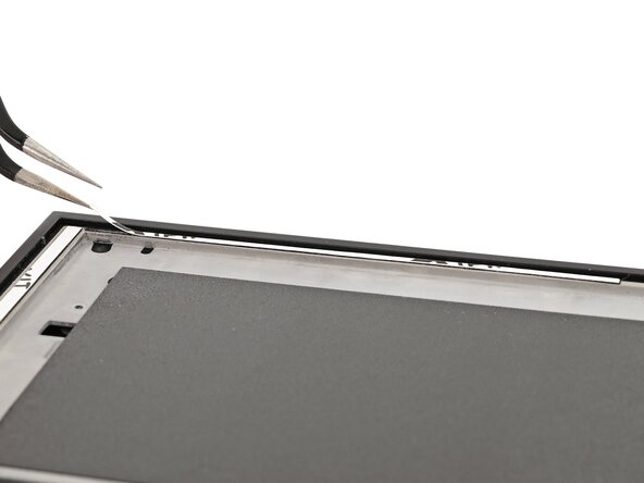
Slide one arm of angled tweezers underneath the sticker from its cutout around the right Joy‑Con 2 connector.
-
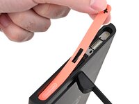
Gently pry up on the sticker until it starts to lift from the console.
-
Leave the tweezers in place to keep the sticker lifted.
-
-
crwdns2935267:0crwdne2935267:0Jimmy$7.95
-
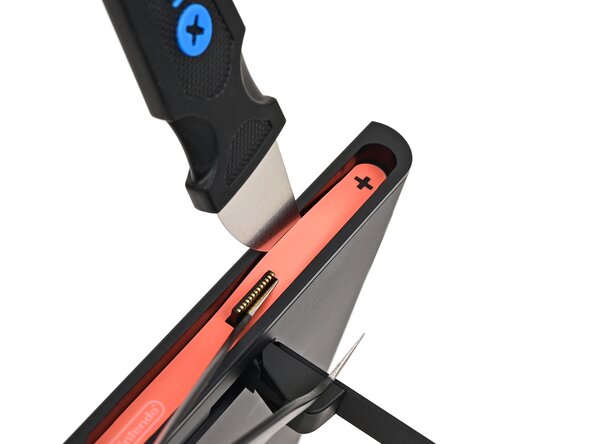
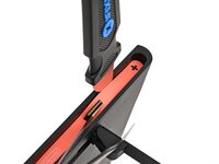
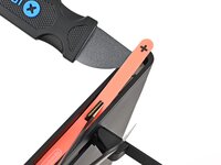
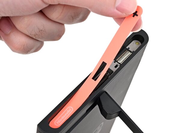
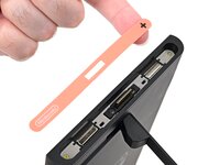
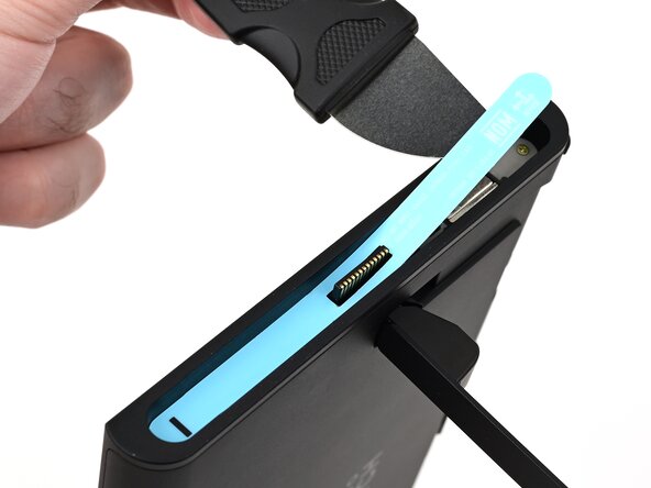
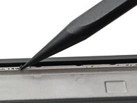
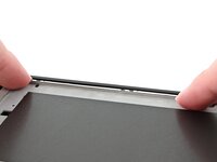
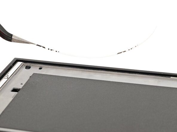
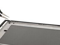
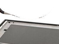
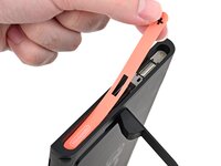
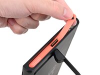
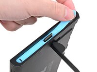
Insert the tip of a Jimmy into the gap formed between the long edge of the console and the sticker.
-
Gently pry up the sticker, working your way up the long edge until the top of the sticker is separated from the console.
-
Remove the tweezers once the sticker is lifted.
-
-
-
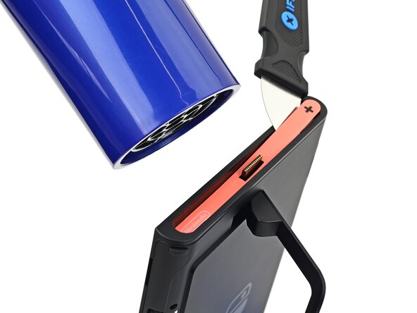
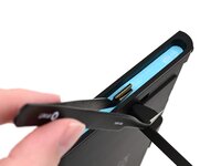
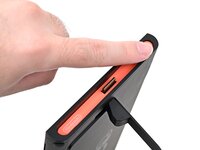
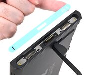
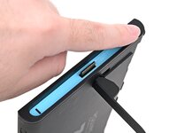
Reheat the bottom of the right side until it's hot to the touch.
-
-
-
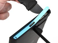
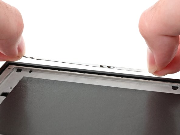
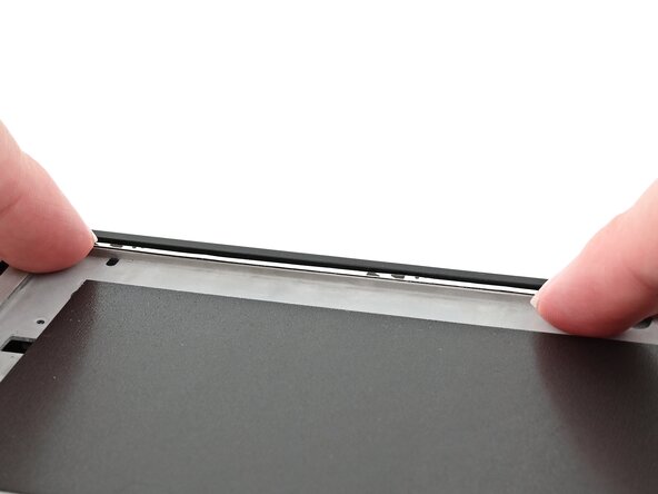
Carefully lift the sticker over the Joy‑Con 2 connector, then peel it up fully to remove it.
-
-
-
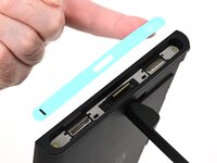
Repeat this procedure to remove the sticker along the left side of the console, labeled with a "-" symbol.
-
-
-
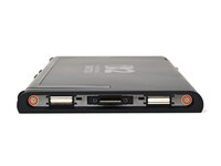
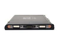
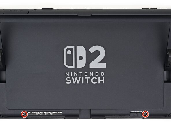
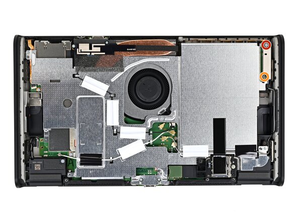
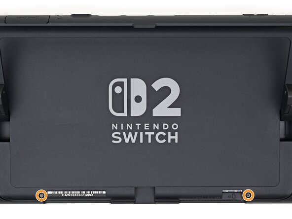
Use a JIS 00 driver to remove the two 3.6 mm‑long gold screws on each side of the console (four in total).
-
-
-
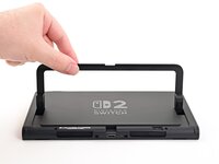
Use your fingers to flip up the kickstand on the back of the console.
-
-
-
Use a Y00 driver to remove the two 4.4 mm‑long screws in the kickstand cutout.
-
-
-
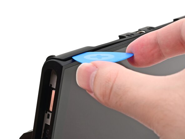
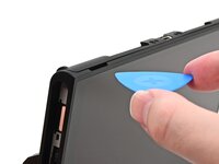
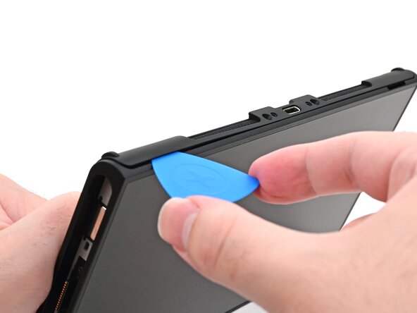
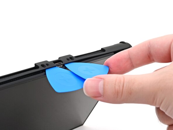
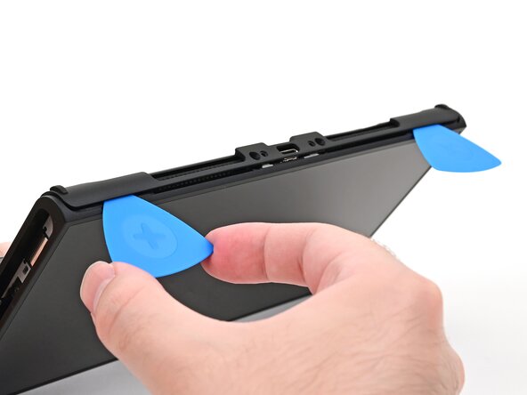
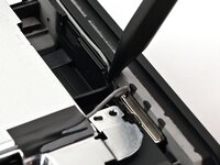
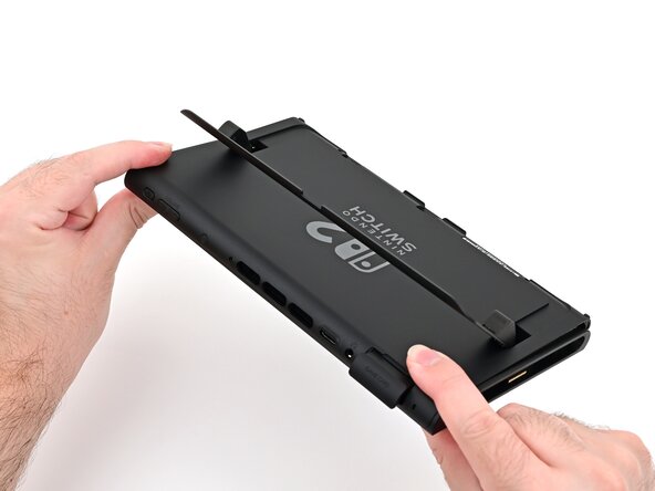
Insert an opening pick into the gap between the back cover and speaker cutout on the bottom edge of the console.
-
-
-
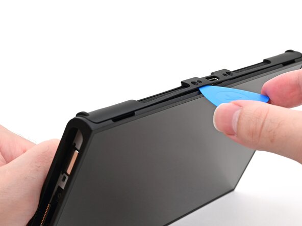
Slide the opening pick towards the USB-C port until it's underneath the screw hole next to the port.
-
-
-
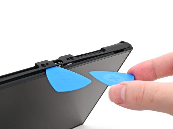
Insert a second opening pick underneath the screw hole on the opposite side of the USB-C port, and slide it to the corner of the console.
-
-
-
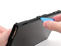
Slide the first opening pick back to where it was first inserted.
-
-
-
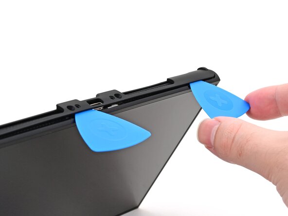
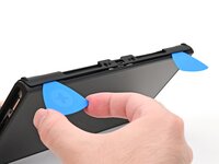
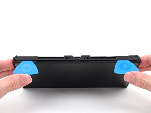
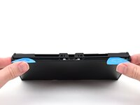
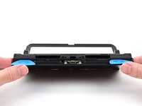
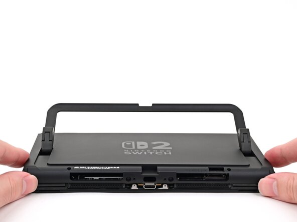
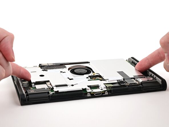
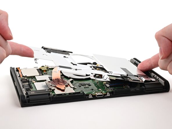
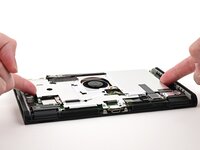
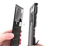
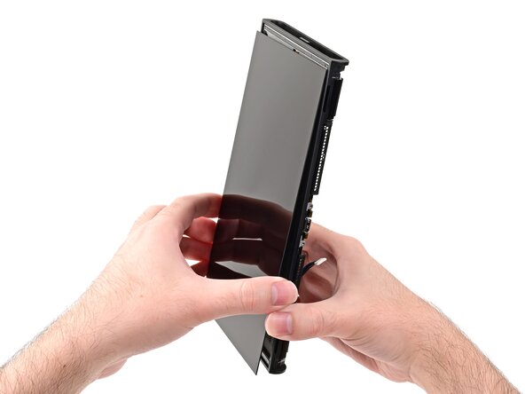
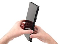
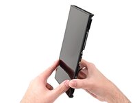
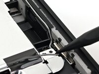
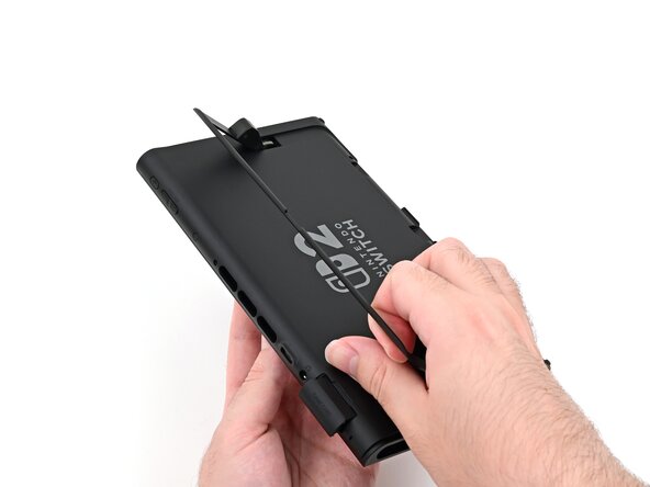
Hold the console with two hands. Rest your thumbs on the opening picks.
-
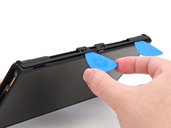
Push up on the opening picks to lift the back cover until it pops up above the USB-C port.
-
-
-
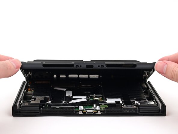
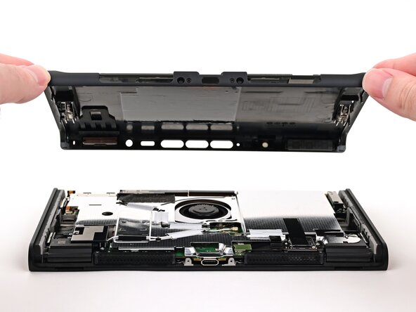
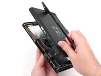
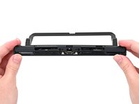
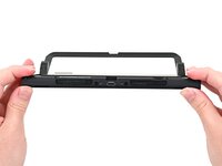
Lift the back cover up from the bottom edge and remove it.
-
-
-
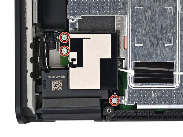
Use a JIS 00 driver to remove the three 4.4 mm‑long silver screws securing the lower antenna.
-
-
-
Use tweezers or your fingers to remove the lower antenna.
-
-
-
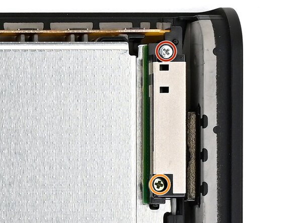
Use a JIS 00 driver to remove the two screws securing the upper antenna:
-
One 4.4 mm‑long silver screw
-
One 4.6 mm‑long green screw
-
-
-
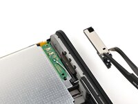
Use tweezers or your fingers to remove the upper antenna.
-
-
-
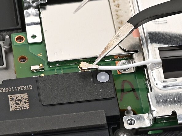
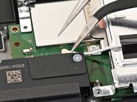
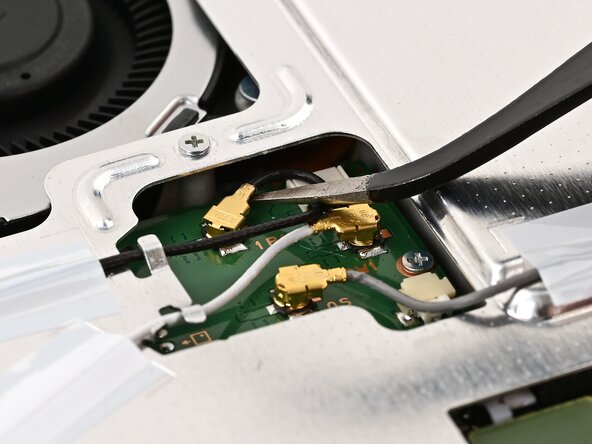
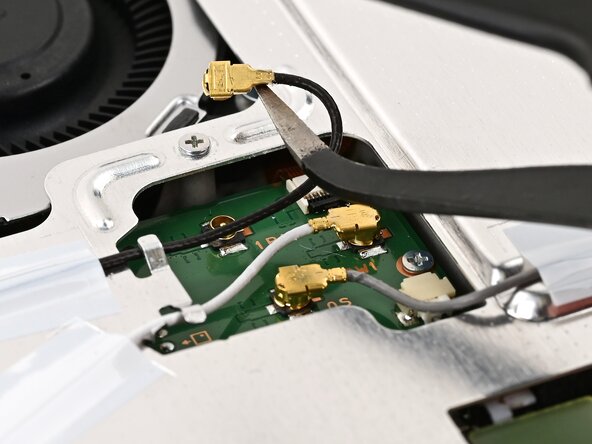
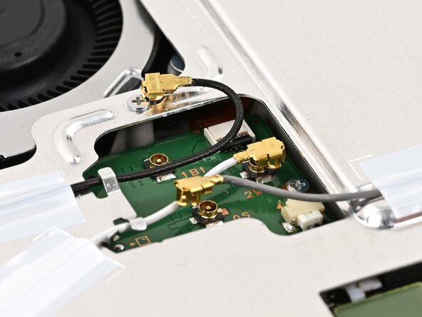
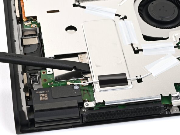
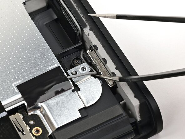
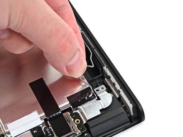
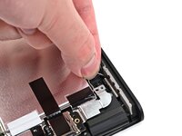
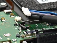
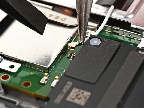
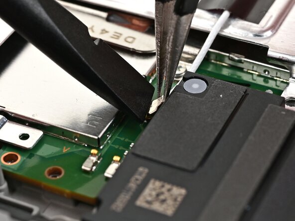
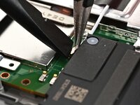
Insert an arm of angled tweezers under the metal neck of the white interconnect cable coaxial connector (located beneath the lower antenna) and lift straight up to disconnect it.
-
-
-
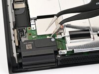
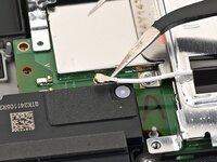
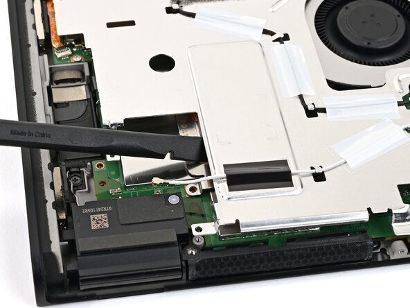
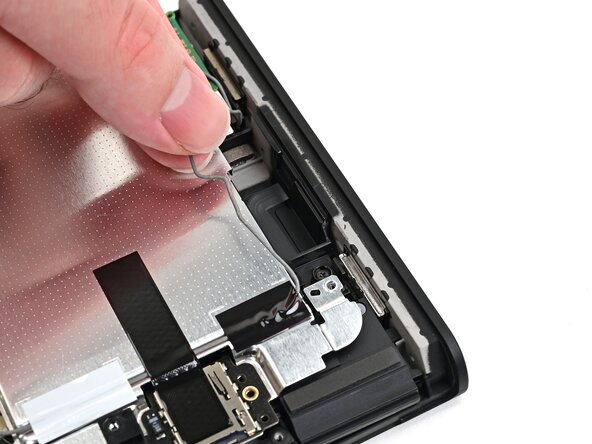
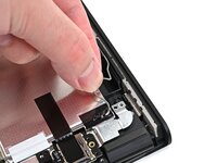
Repeat this procedure to disconnect the three central coaxial connectors from the board.
-
-
-
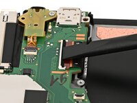
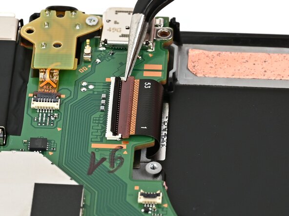
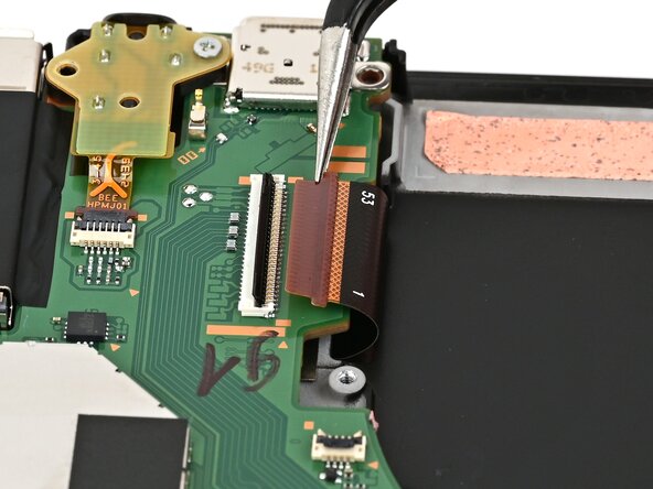
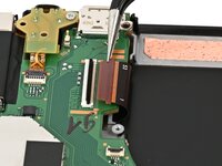
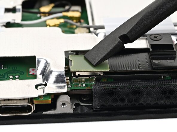
Use the flat end of a spudger to pry up and disconnect the MicroSD card reader press connector, located next to the bottom USB‑C port.
-
-
-
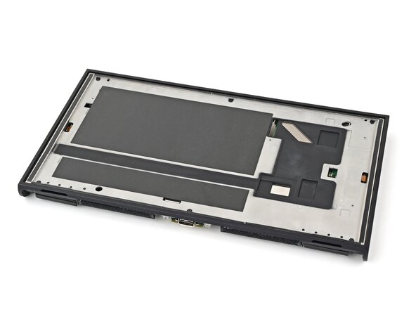
Use a JIS 00 driver to remove the seven screws securing the shield plate:
-
Two 6.2 mm‑long silver screws
-
Five 4.4 mm‑long silver screws
-
-
-
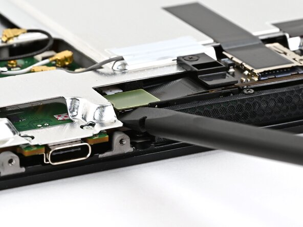
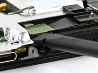
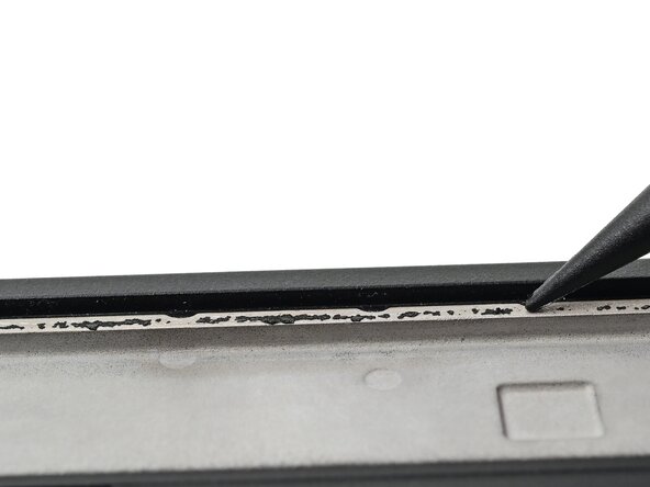
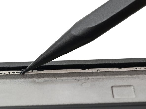
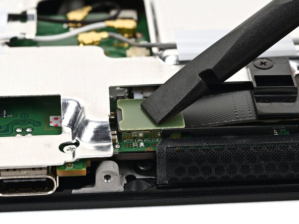
Insert the flat end of a spudger between the shield plate and the processor's heat sink, next to the square (⛶) marking on the shield plate.
-
Twist the spudger to lift the shield plate and separate the thermal putty bonded to it. Keep lifting the shield plate until you don't feel resistance.
-
-
-
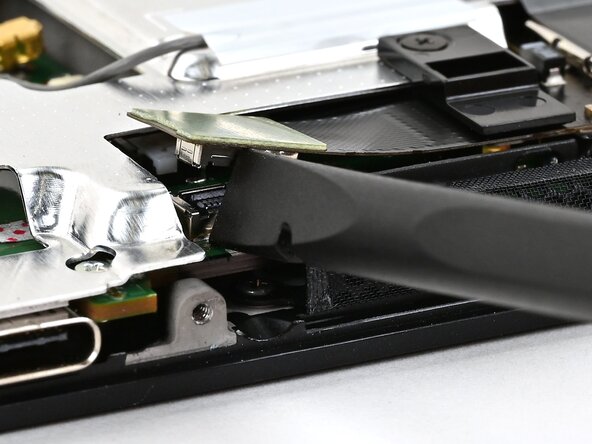
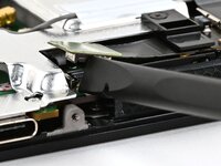
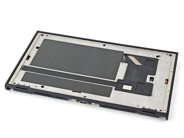
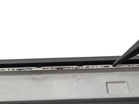
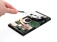
Lift the left edge of the shield plate to ensure it's fully separated from the thermal putty.
-
Gently set the shield plate back down.
-
-
-
-
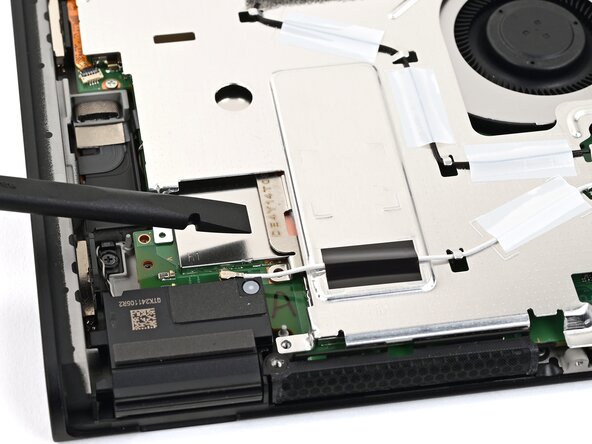
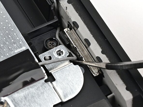
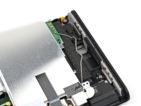
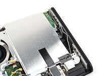
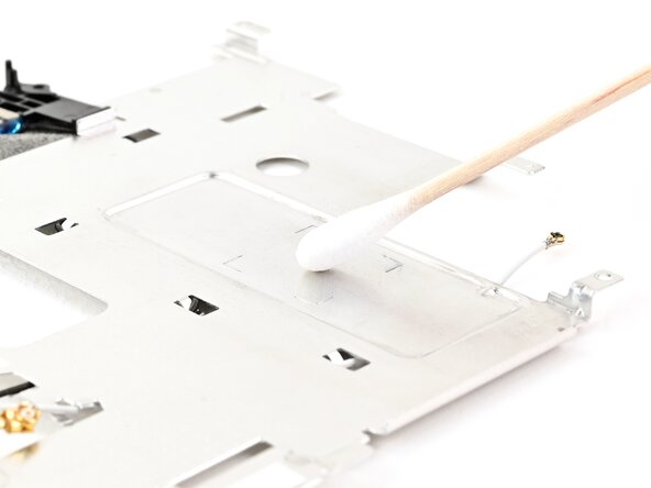
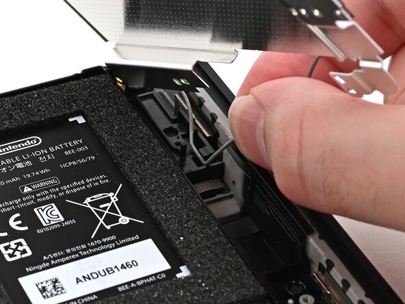
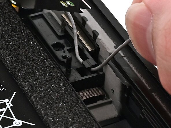
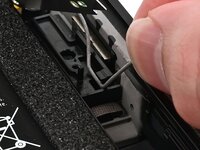
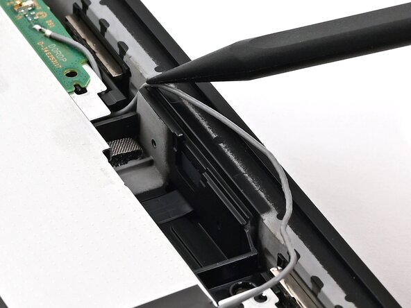
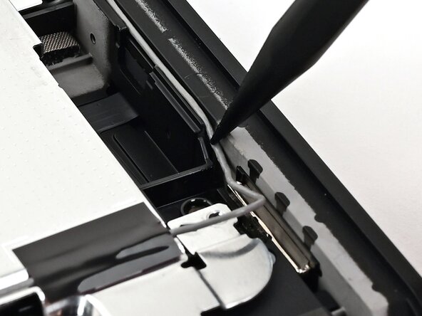
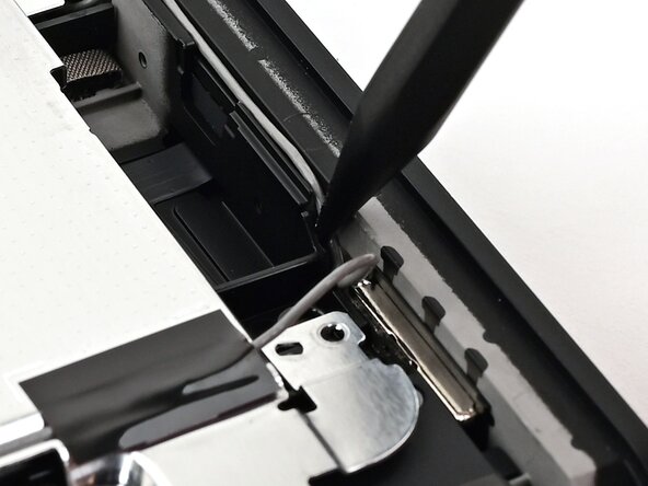
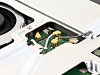
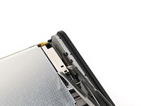
Insert one arm of angled tweezers underneath the gray antenna cable at the bottom-right corner of the console.
-
Lift the cable out of the black clip securing it to the frame.
-
-
-
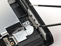
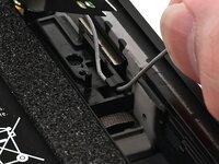
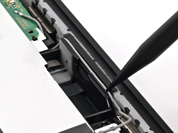
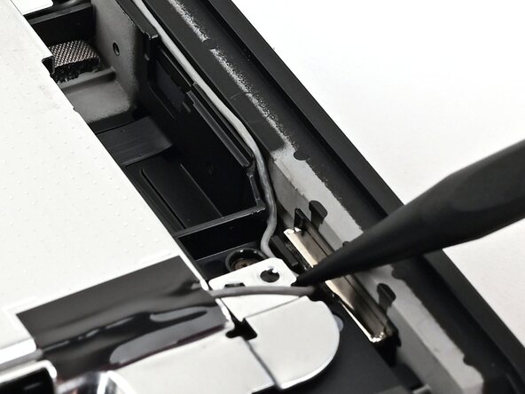
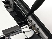
Unroute the gray antenna cable from its channel along the right edge of the console.
-
-
-
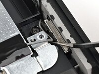
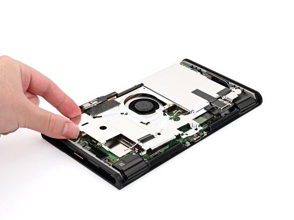
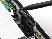
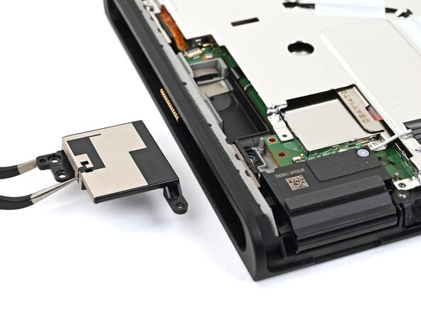
Lift and slide the shield plate away from the right edge of the console until the gray antenna cable is completely free.
-
-
-
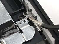
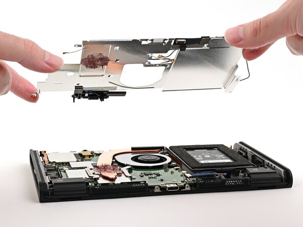
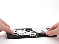
Pick up and remove the shield plate.
-
-
-
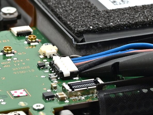
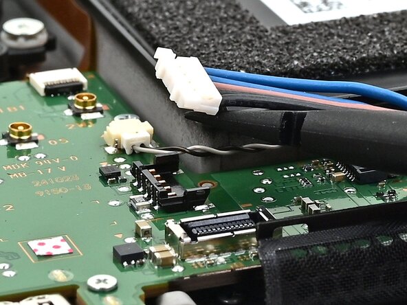
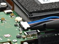
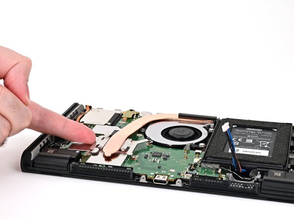
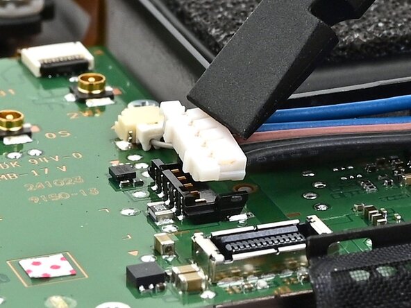
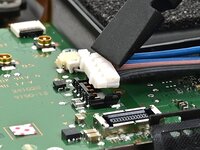
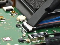
Insert the flat end of a spudger underneath the flat-topped battery connector, located next to the battery, and pry up to disconnect it.
-
-
crwdns2935267:0crwdne2935267:0Arctic Silver ArctiClean$9.99
-
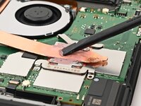
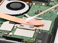
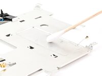
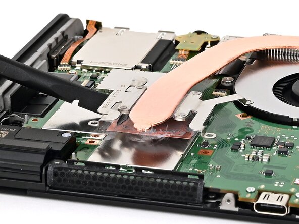
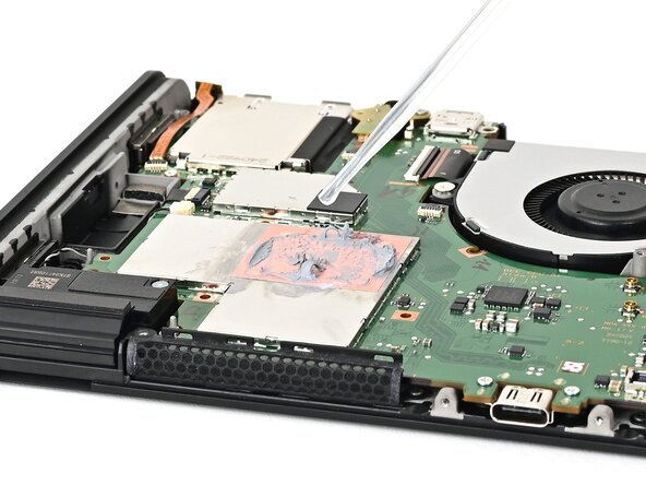
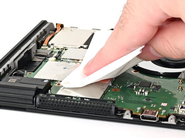
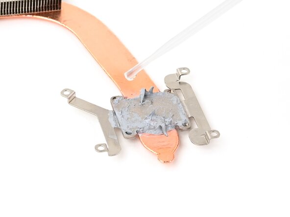
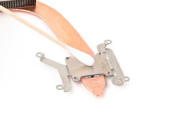
Use the flat end of a spudger to scrape off the thermal putty on top of the copper heat pipe.
-
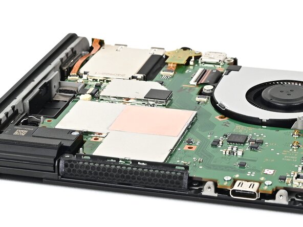
Apply high-concentration (90% or higher) isopropyl alcohol or thermal material remover to a cotton swab or lint-free cloth and wipe away any remaining thermal putty on both the heat pipe and shield plate.
-
-
-
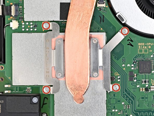
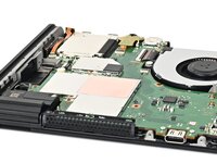
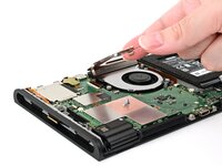
Use a JIS 00 driver to remove the four 3.4 mm‑long silver screws securing the heat sink.
-
-
-
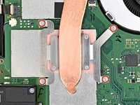
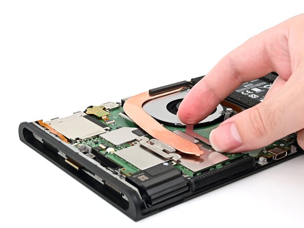
Insert the flat end of a spudger between the heat sink and the processor's heat spreader.
-
Twist the spudger to lift the heat sink and separate the thermal paste bonded to it.
-
-
-
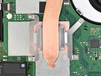
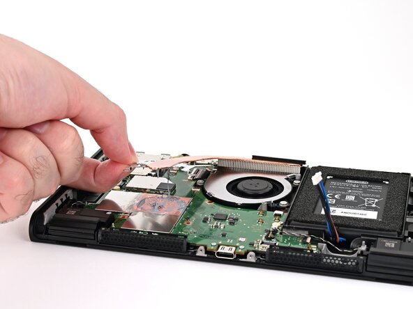
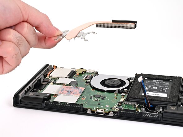
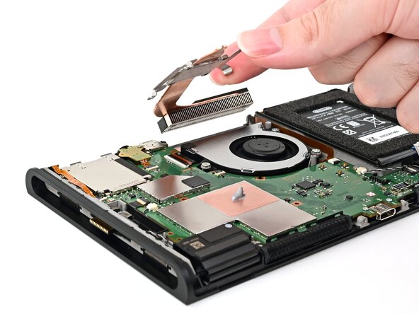
Slowly lift the heat sink from the front, until the aluminum fin stack at the back is detached from the adhesive beneath it.
-
Remove the heat sink.
-
-
crwdns2935267:0crwdne2935267:0Arctic Silver ArctiClean$9.99
-
Use high-concentration (90% or higher) isopropyl alcohol or thermal material remover to soak the thermal paste on the processor's heat spreader for one minute.
-
Use a lint-free cloth or cotton swabs to wipe away the thermal paste.
-
Repeat this process until the processor's heat spreader is clean.
-
-
-
Repeat this process to clean the thermal paste off the bottom of the heat sink.
-
-
-
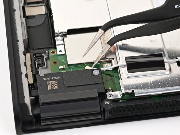
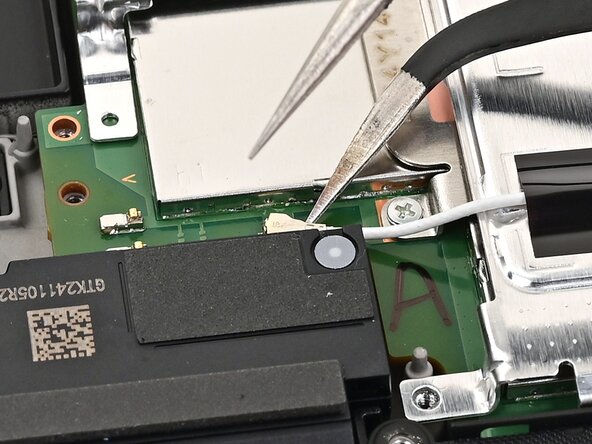
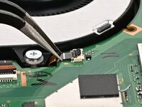
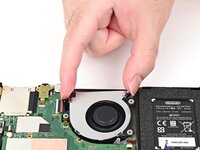
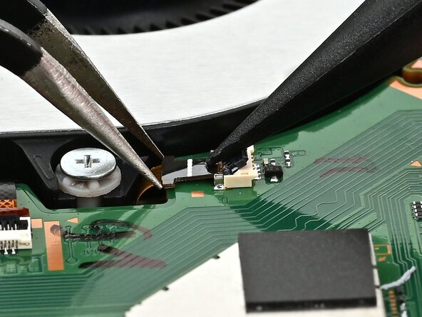
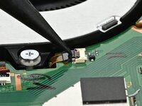
Use the point of a spudger to flip up the locking flap on the fan cable ZIF connector, located next to the fan on the console's board.
-
-
-
Use tweezers or your fingers to gently pull the cable out of its socket.
-
-
-
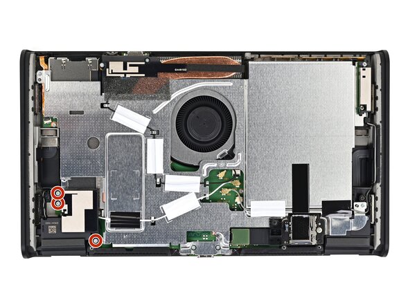
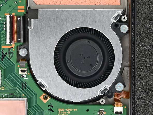
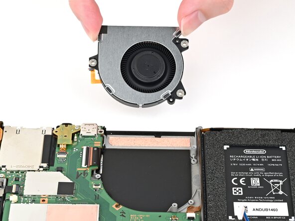
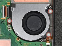
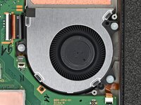
Use a JIS 00 driver to remove the three 5.2 mm‑long silver screws securing the fan.
-
-
-
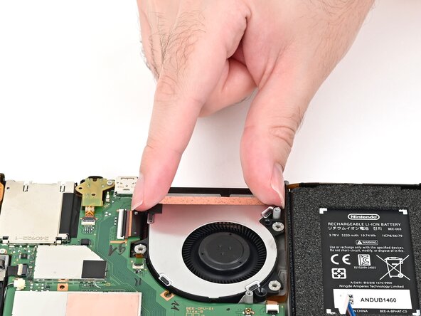
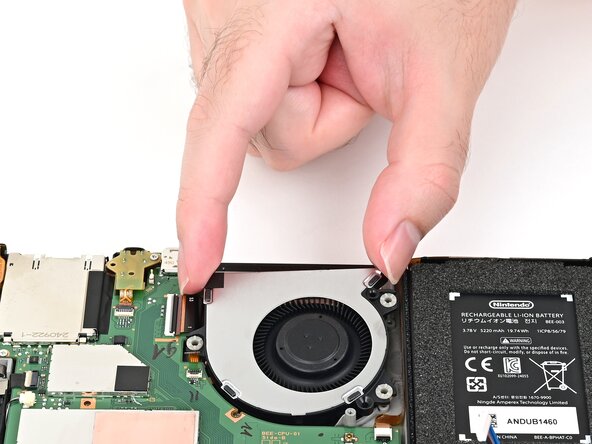
Slide the fan out of its recess to free its cable, then pick it up to remove it.
-
-
-
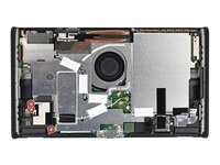
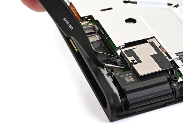
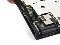
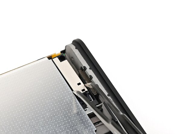
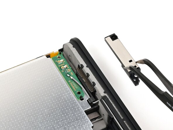
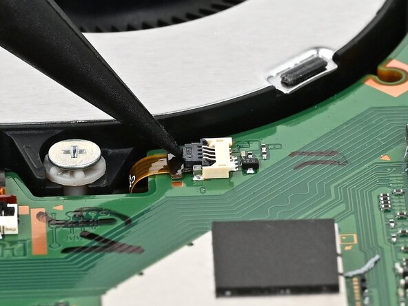
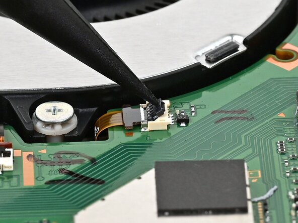
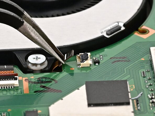
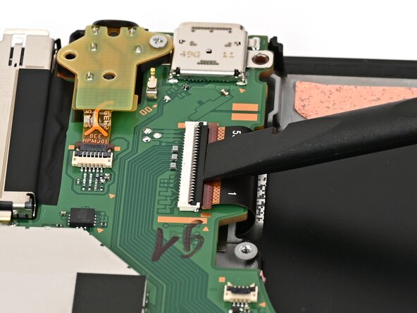
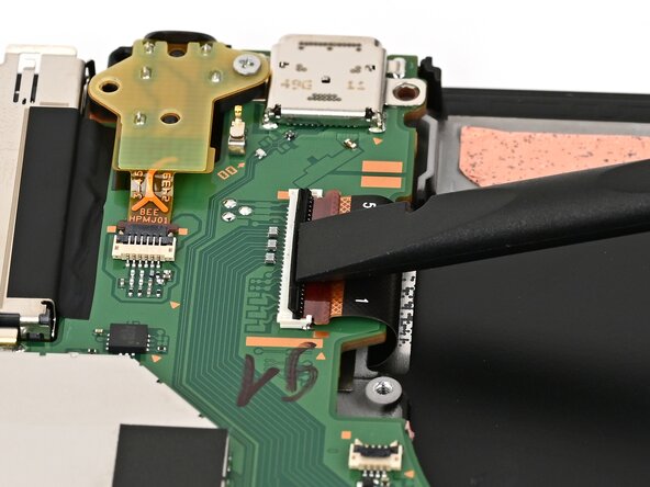
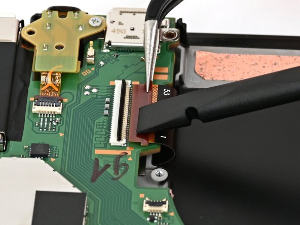
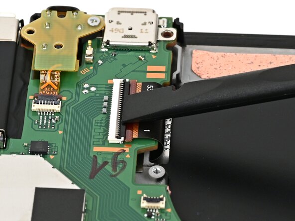
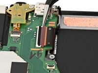
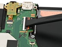
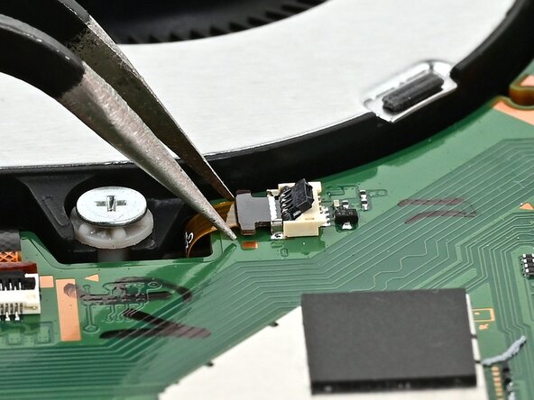
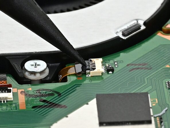
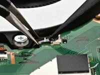
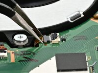
Use your finger or the flat end of a spudger to flip up the locking flap on the screen cable ZIF connector.
-
-
-
Use tweezers or your fingers to gently pull the cable out of its connector.
-
-
-
Flip the console over so the screen is facing up.
-
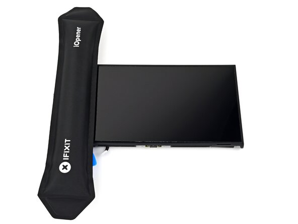
Apply a heated iOpener to the bottom edge of the screen for two minutes.
-
-
-
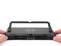
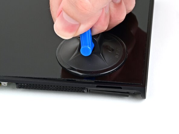
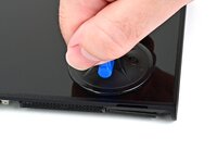
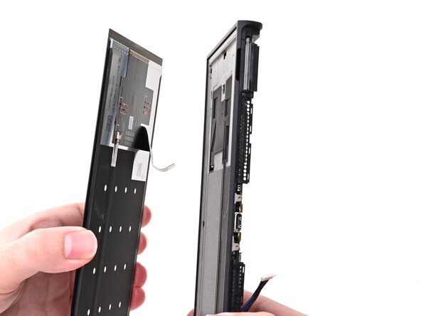
Apply a suction handle to the bottom edge of the screen, above the right speaker and ventilation cutouts.
-
Pull up on the handle with a strong, steady force to create a gap between the screen and the frame.
-
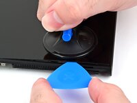
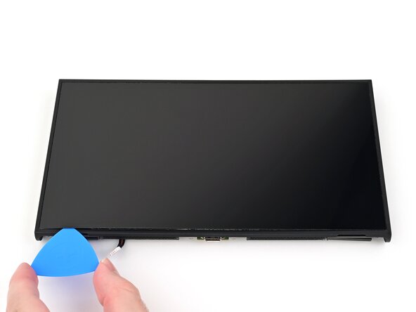
Insert the tip of an opening pick into the gap.
-
-
-
Slide your pick across the bottom edge to separate the adhesive.
-
Leave your pick inserted in the bottom left corner to prevent the adhesive from resealing.
-
-
-
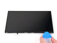
Apply a heated iOpener to the left edge of the screen for two minutes.
-
-
-
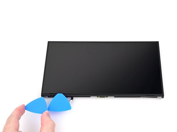
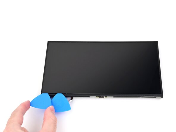
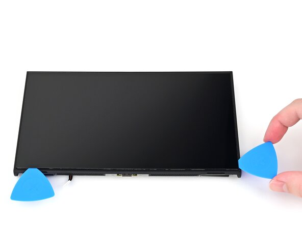
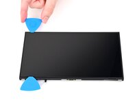
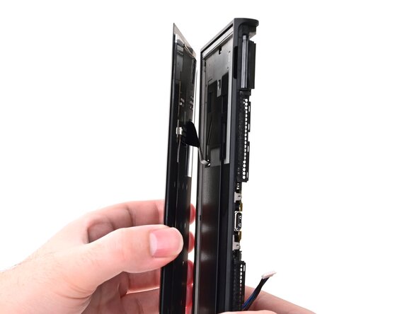
Insert a second opening pick next to the first one and slide it up the left edge of the screen.
-
-
-
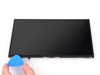
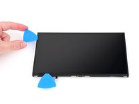
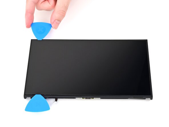
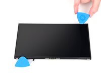
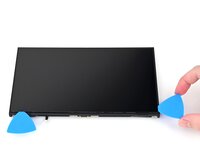
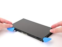
Repeat the heating and sliding procedure along the remaining screen edges.
-
-
-
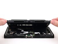
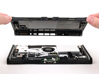
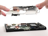
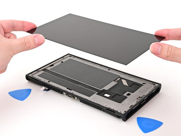
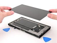
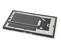
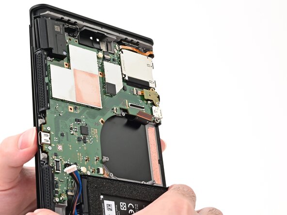
Lift the screen off the frame to remove it.
-
-
-
Congratulations on completing disassembly! The remaining steps will show how to reassemble your console.
-
-
crwdns2935267:0crwdne2935267:0Adhesive Cleanup Kit (Set of 12)$7.99
-
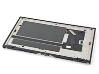
Use the point of a spudger to scrape off any adhesive left on the frame.
-
Apply a bit of isopropyl alcohol to a cotton swab or lint-free cloth and clean the frame until it's free of adhesive residue.
-
-
crwdns2935267:0crwdne2935267:0Tesa 61395 Tape$2.99
-
Use your fingers to install strips of thin, double-sided tape to the raised lip along the edges of the frame. Use 1 mm strips for the top and bottom edges and 2 mm strips for the sides.
-
-
-
Use angled tweezers to peel off all liners from the adhesive.
-
-
-
Align the screen's cable with its cutout in the frame.
-
Route the cable through its cutout, ensuring it reaches its connector on the board.
-
-
-
Align the right edge of the screen with its recess in the frame.
-
Press the right edge of the screen into place, then work your way to the left edge until the entire screen is adhered to the frame.
-
-
-
Use tweezers or your fingers to slide the screen cable into its ZIF connector until it's fully seated.
-
Flip the hinged locking flap down to secure the cable.
-
-
-
Slide the fan into its recess. Ensure its cable slides underneath the edge of the board.
-
Align the fan with its screw posts on the frame.
-
-
-
Use a JIS 00 driver to install the three 5.2 mm‑long silver screws securing the fan.
-
-
-
Use tweezers or your fingers to slide the fan cable into its ZIF connector until it's fully seated.
-
Flip the hinged locking flap down to secure the cable.
-
-
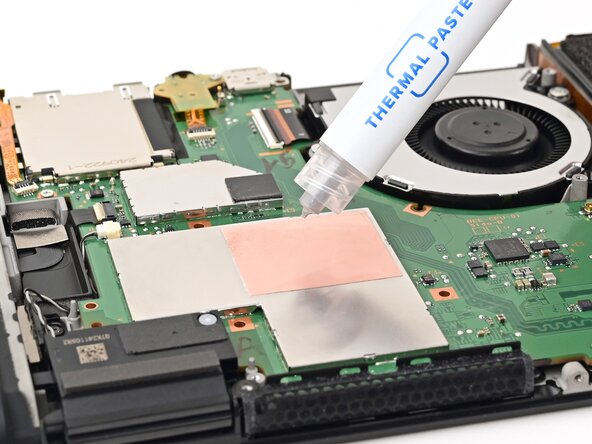
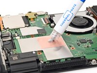
crwdns2935267:0crwdne2935267:0iFixit Thermal Paste$9.95
-
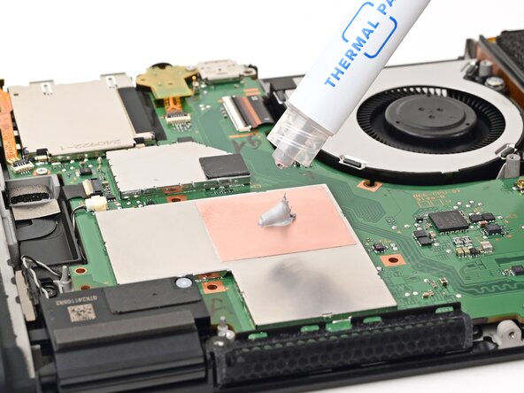
Apply a bead of new thermal paste to the center of the processor's copper heat spreader, roughly the size of a pea.
-
-
-
Set the heat sink's aluminum fins into its recess behind the fan, then lower the heat sink onto the board.
-
-
-
Use a JIS 00 driver to partially install the four 3.4 mm‑long silver screws securing the heat sink.
-
Tighten the screws in an X pattern. For example: bottom left, top right, bottom right, then top left.
-
-
-
Align the battery connector over its socket on the board.
-
Use your finger or the flat end of a spudger to press the battery connector onto its socket until it's fully seated.
-
-
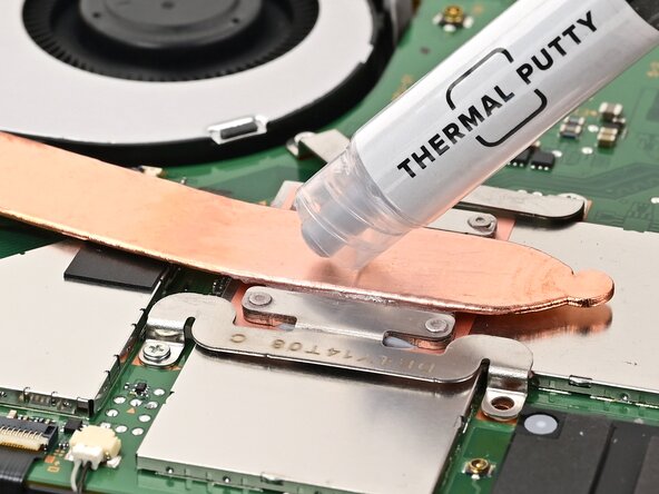
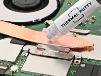
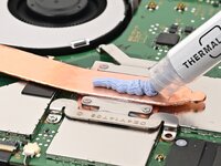
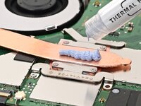
crwdns2935267:0crwdne2935267:0iFixit Thermal Putty$9.95
-
Apply a line of new thermal putty down the center of the heat pipe, roughly the thickness of a pea.
-
-
-
Hold the top‑right corner of the shield plate above the top‑right corner of the console.
-
Route the gray antenna cable underneath the black hook near the top corner of the frame.
-
-
-
Lower the shield plate into place and align it with its screw holes.
-
-
-
Route the gray antenna cable down its channel on the right edge of the frame.
-
-
-
Press the gray antenna cable into its groove at the bottom of its channel, and continue routing until it's secured to the clip at the bottom of the frame.
-
-
-
Use a JIS 00 driver to install the seven screws securing the shield plate:
-
Two 6.2 mm‑long silver screws
-
Five 4.4 mm‑long silver screws
-
-
-
Use your finger or the flat end of a spudger to press the MicroSD card reader press connector onto its socket on the board.
-
-
-
Use tweezers to hold the lower antenna coaxial connector in place over its socket and gently press down with your finger or a spudger—the connector should "snap" into place. If you're having trouble, reposition the head instead of using more force.
-
Repeat this process to connect the three central coaxial connectors to their respective sockets.
-
-
-
Use tweezers or your fingers to align the upper antenna with its screw holes and black alignment pegs and set it into place.
-
Use a JIS 00 driver to install the two screws securing the upper antenna:
-
One 4.4 mm‑long silver screw
-
One 4.6 mm‑long green screw
-
-
-
Use tweezers or your fingers to align the lower antenna with its screw holes and gray alignment pegs and set it into place.
-
Use a JIS 00 driver to install the three 4.4 mm‑long screws securing the lower antenna.
-
-
-
Fully pull out the game card tray.
-
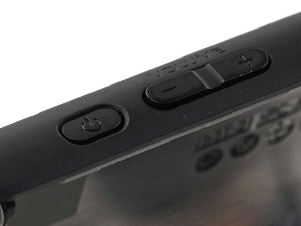
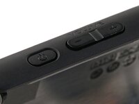
Double-check the power and volume buttons to ensure they're seated correctly. If the rubber membrane beneath the buttons is out of place, ensure it's aligned with its pegs.
-
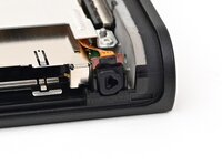
Check the microphone to ensure it's fully seated in its slot in the frame.
-
-
-
Align the top of the back cover with the top of the console.
-
Set the top edge of the back cover into place, checking the buttons and ports to ensure they're aligned properly. If they aren't, lift the back cover and try again.
-
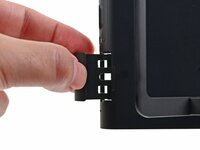
Press along the top edge to fasten the clips securing the back cover to the console.
-
-
-
Squeeze the rest of the back cover and console together to fasten the clips.
-
-
-
Use a JIS 00 driver to install the three 3.1 mm‑long screws securing the back cover: one on the top edge of the console, and two on either side of the bottom USB-C port.
-
Use a Y00 driver to install the two 4.4 mm‑long screws in the kickstand cutout.
-
-
-
Install the two 3.6 mm‑long gold screws on each side of the console (four in total).
-
-
-
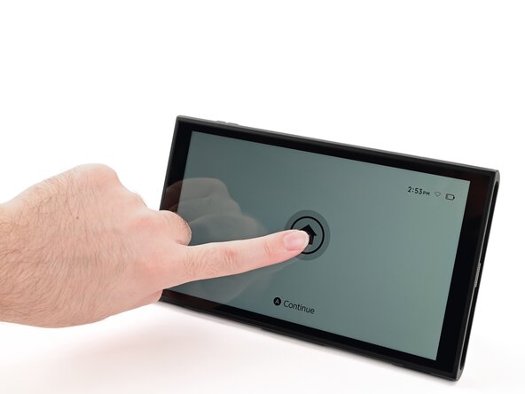
Power on the console and test functionality to ensure it's working as expected.
-
-
-
Align the right side sticker with its recess. Ensure the cutout in the sticker is aligned with the Joy-Con connector.
-
Set the sticker into its recess, first on one side, then the other.
-
Use your finger or the flat end of a spudger to press the sticker into place.
-
-
-
Repeat this procedure to install the left side sticker.
-


You finished fixing your Switch 2!
Take your e-waste to an R2 or e-Stewards certified recycler.
Repair didn’t go as planned? Try some basic troubleshooting, or ask our Nintendo Switch 2 Answers Community for help.

crwdns2947412:02crwdne2947412:0
Where can I find replacement screen?
They're not available yet! We'll update the guide once we have the part.