crwdns2915892:0crwdne2915892:0
Follow this guide to replace the rear camera in your Microsoft Surface Pro 11.
If the images from your rear camera are blurry and grainy or the camera isn't taking photos at all, it may be time to replace the rear camera.
You'll need replacement screen adhesive to complete this repair.
Note: Surface Pro 11 replacement parts differ depending on whether your device has an LCD or OLED screen. Before purchasing parts and consumables, make sure you know which type of screen your device has so you can select the correct parts for your repair.
crwdns2942213:0crwdne2942213:0
-
-
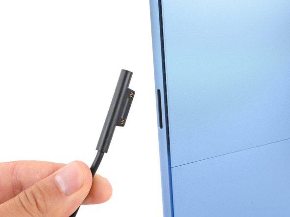
Unplug all cables and fully shut down your laptop.
-
-
-
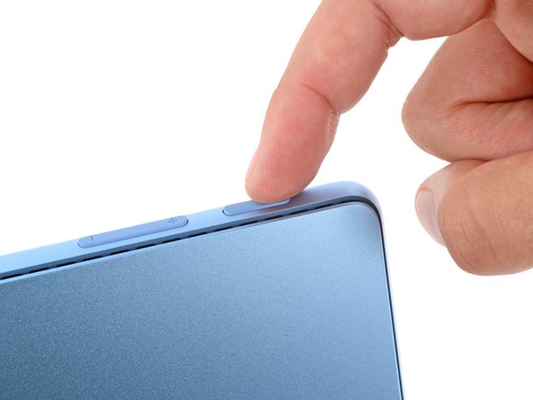
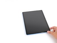
Lay your Surface Pro screen side down and open the kickstand to about a 90‑degree angle.
-
-
-
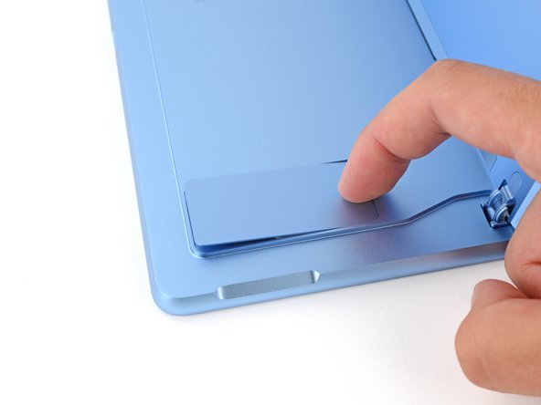
Use your finger to firmly press down on the SSD door indent until the door pops up.
-
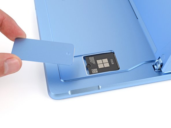
Remove the SSD door.
-
-
-
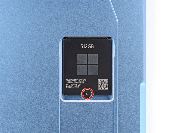
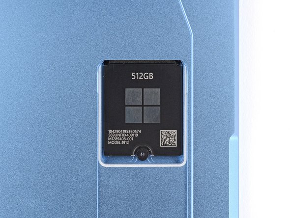
Use a Torx Plus 3IP screwdriver to remove the 2.4 mm‑long screw securing the SSD.
-
-
-
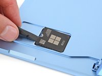
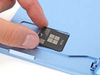
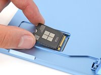
Use the flat end of a spudger to gently lift the notched edge of the SSD enough that you can grip the bottom corners with your fingers.
-
Use your fingers or tweezers to pull the SSD straight out of its socket and remove it.
-
-
-
2 mm on the left, right, and bottom edges
-
Don't insert your tool at all near the front facing camera on the top edge
-
8 mm along the top edge (everywhere besides the front facing camera area)
-
-
-
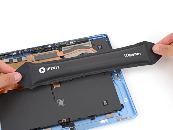
Heat an iOpener and lay it on the right edge of the screen for two minutes to soften the adhesive.
-
-
-
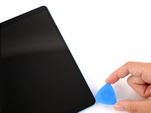
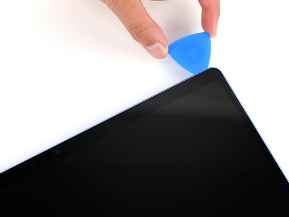
Insert the tip of an opening pick under the screen near the bottom of the right speaker cutout.
-
Slide your pick towards the bottom edge and slightly rotate it so the tip goes under the notch in the screen.
-
-
-
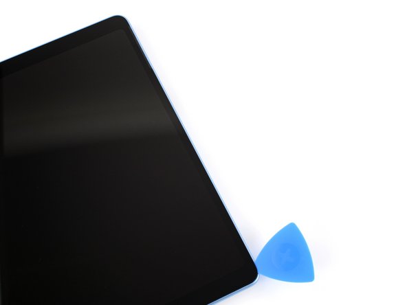
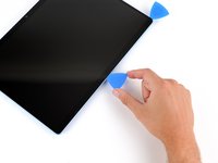
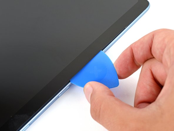
Slide your pick down the right edge to separate the adhesive securing it.
-
Leave your pick inserted under the bottom right corner to prevent the adhesive from re‑sealing.
-
-
-
Heat the bottom edge of the screen with an iOpener, hair dryer, or heat gun to soften the adhesive.
-
-
-
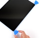
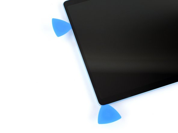
Insert a second pick under the bottom right corner of the screen and slide it along the bottom edge to separate the adhesive.
-
Leave your second pick inserted under the bottom left corner to prevent the adhesive from re‑sealing.
-
-
-
Heat the left edge of the screen with an iOpener, hair dryer, or heat gun to soften the adhesive.
-
-
-
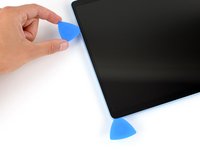
Insert a third pick under the bottom left corner of the screen and slide it up the left edge, stopping when you get to the bottom of the left speaker cutout.
-
Leave the pick inserted under the screen to prevent the adhesive from re-sealing.
-
-
-
Heat the top edge of the screen with an iOpener, hair dryer, or heat gun to soften the adhesive.
-
-
-
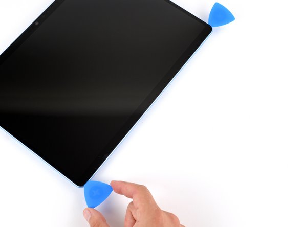
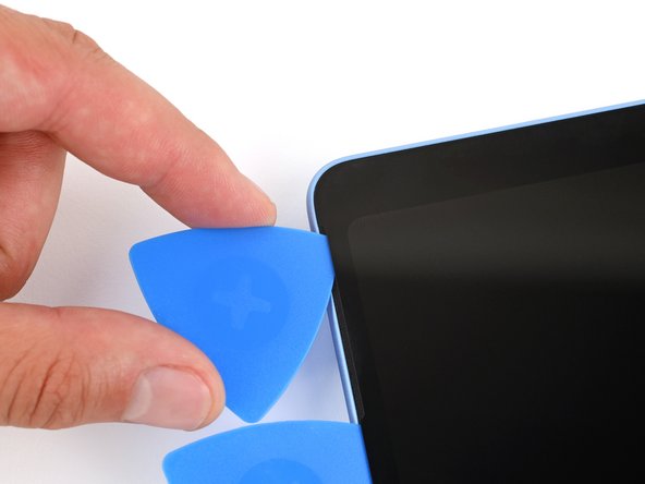
Insert a fourth pick under the screen near the top of the left speaker cutout.
-
Slide your pick towards the top edge and slightly rotate it so the tip goes under the notch in the screen.
-
-
-
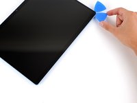
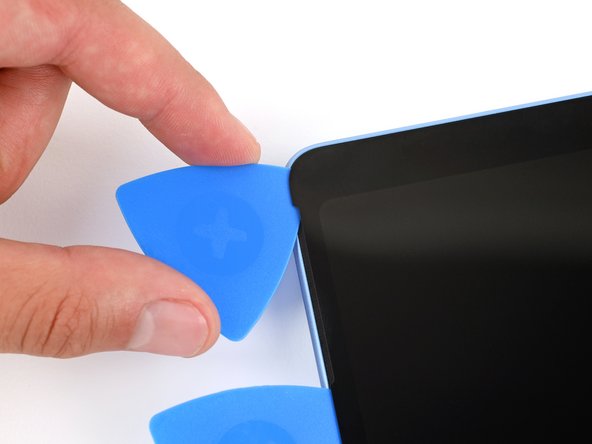
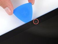
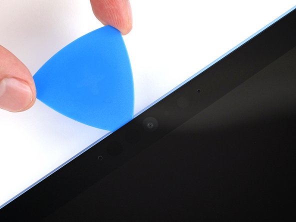
Slide the pick along the top edge and stop before you get to the front facing camera.
-
-
-
-
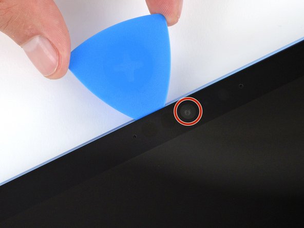
Remove the pick enough that it can pass above the front facing camera.
-
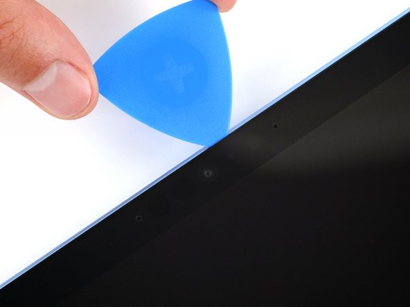
Slide the pick along the top edge until it's past the camera.
-
-
-
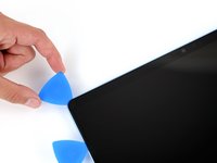
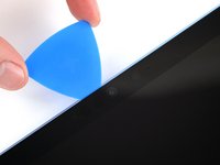
Insert your pick 8 mm under the screen and slide it to the top right corner to separate the remaining adhesive.
-
-
-
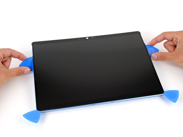
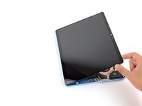
Insert the flat edge of two picks under the screen, below the two speaker cutouts.
-
Use the picks to gently pry up the screen, fully separating it from the frame.
-
If the screen feels stuck anywhere, use your pick to separate the adhesive in that area. Remember not to insert your pick too far under the screen.
-
-
-
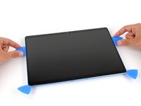
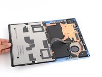
Once the screen is fully separated, flip the top edge over the bottom edge and lay the screen down flat, being careful not to strain the ribbon cable.
-
-
-
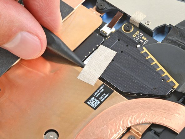
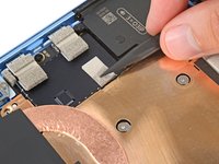
Use the tip of a spudger to lift the conductive tape off the copper shield, near the center of your device.
-
-
-
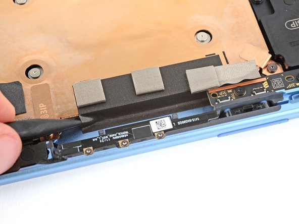
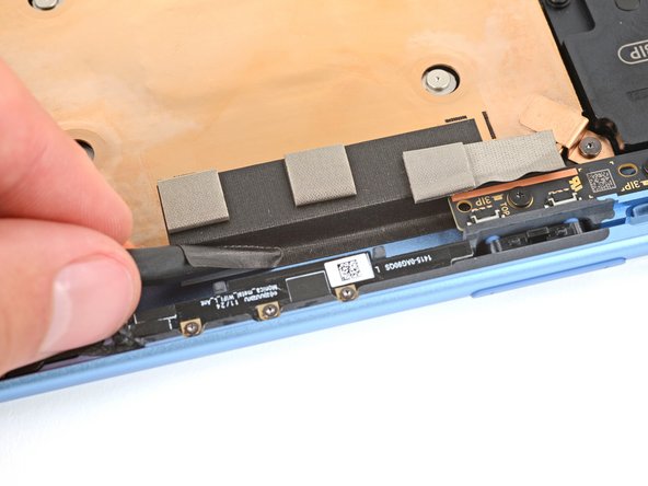
Insert an arm of a pair of angled tweezers in one of the gaps on the edge of the screen cable shield.
-
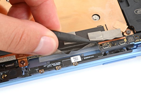
Use your tweezers to gently pry up and remove the shield.
-
-
-
Insert the flat end of a spudger under the notched corner of the screen cable press connector and pry up to disconnect it.
-
-
-
Grip the screen with both hands and remove it.
-
-
crwdns2931653:025crwdne2931653:0 Disconnect the Surface Connect port
crwdns2944590:025crwdnd2944590:030crwdnd2944590:0crwdnd2944590:0crwdne2944590:0
-
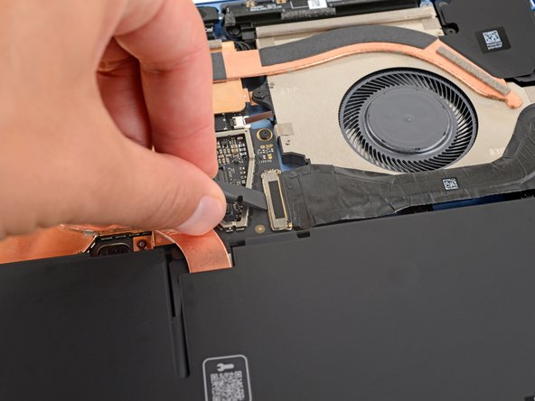
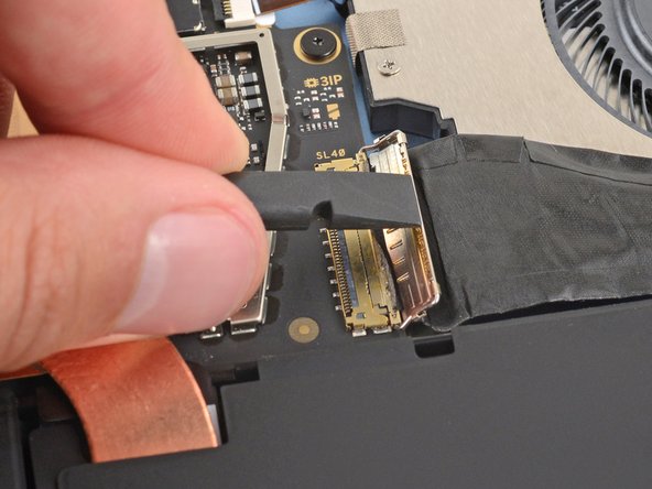
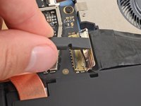
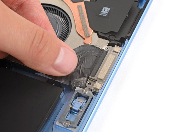
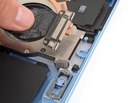
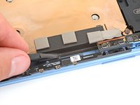
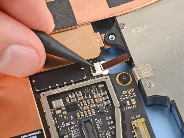
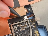
Use the flat end of a spudger or a clean fingernail to flip up the metal buckle on the Surface Connect port cable.
-
-
-
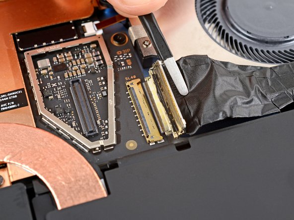
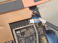
Use tweezers or your fingers to firmly grip the Surface Connect port cable close to the connector head and pull it straight out of the socket.
-
Remove any adhesive liners from the Surface Connect port cable or bottom edge of the fan.
-
Use tweezers or your fingers to insert the cable's connector into its socket.
-
Flip the metal buckle over the connector and firmly press around its perimeter until it snaps into place.
-
Firmly press the cable into place on the fan to secure it with the adhesive.
-
-
-
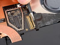
Use a Torx Plus 3IP screwdriver to remove the two 3.6 mm‑long screws securing the Surface Connect port to the frame.
-
-
-
Heat an iOpener and lay it on the Surface Connect port cable for two minutes to soften the adhesive.
-
-
crwdns2935267:0crwdne2935267:0Tesa 61395 Tape$2.99
-
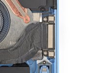
Grip the Surface Connect cable by the end with the motherboard connector and peel the cable from the fan.
-
If you're reinstalling the original port, the adhesive should be sticky enough to reuse.
-
-
-
Lift the Surface Connect port out of its recess in the frame and remove it.
-
Put the Surface Connect port into place so its cutouts go over their frame posts. Make sure the port is fully in its cutout—the outer edge should be flush with the frame.
-
Install the two screws that secure the port.
-
-
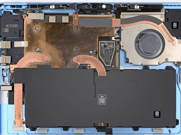
crwdns2931653:031crwdne2931653:0 Detach the thermal module tape
crwdns2944590:031crwdnd2944590:037crwdnd2944590:0crwdnd2944590:0crwdne2944590:0
-
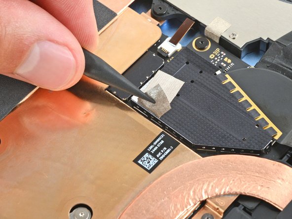
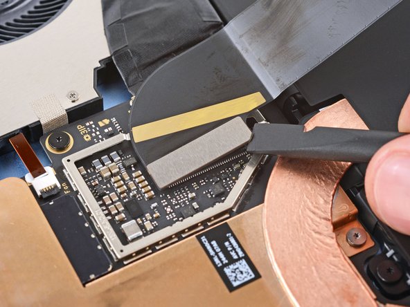
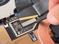
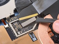
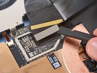
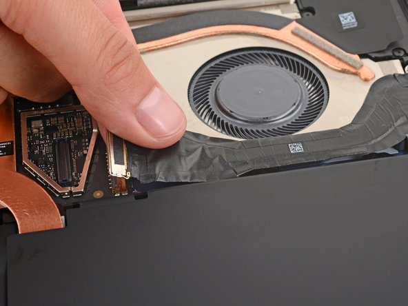
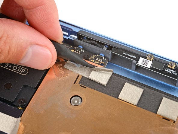
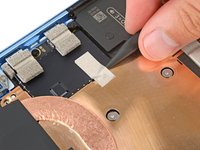
Use the point of a spudger to lift the two pieces of silver conductive tape from the top left corner of the thermal module.
-
-
-
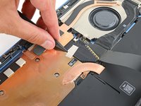
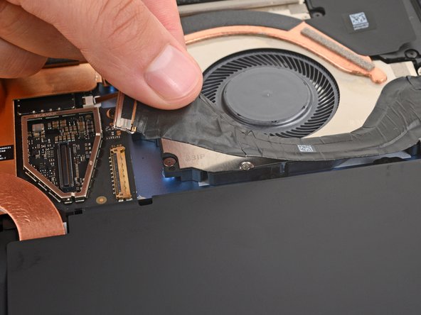
Use the point of a spudger to lift the black conductive tape on the thermal module's top edge, detaching it from the frame.
-
-
-
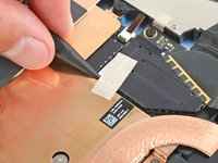
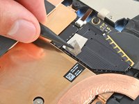
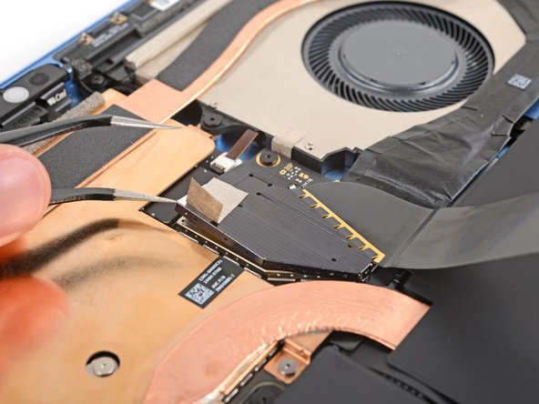
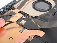
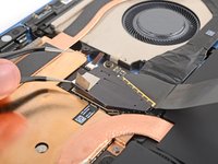
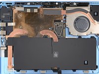
Use the point of a spudger to lift the black locking flap on the fan cable ZIF connector, near the center of the fan's left edge.
-
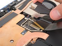
Use tweezers to grip the cable's plastic pull tab and gently slide the cable out of its socket.
-
-
-
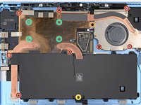
Use a Torx Plus 3IP screwdriver to remove the 14 screws securing the thermal module and fan assembly:
-
Eight 2.6 mm‑long screws
-
One 2.8 mm‑long screw near the top of the fan's left edge
-
One 3.7 mm‑long screw near the center of the battery's bottom edge
-
Four 2.4 mm‑long CPU tension screws in the center of the thermal module
-
-
-
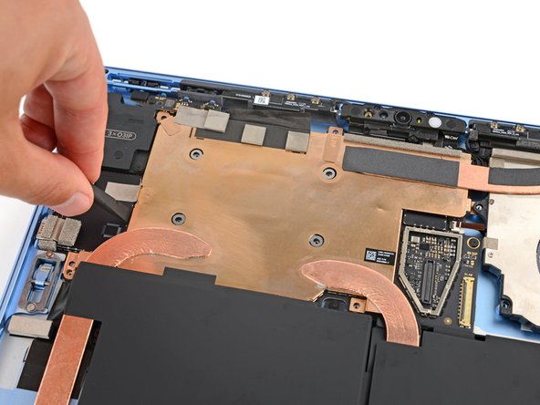
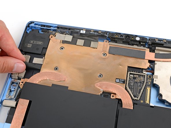
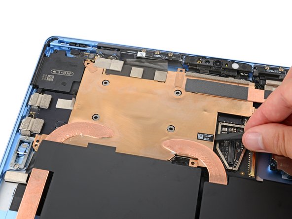
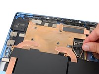
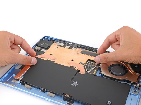
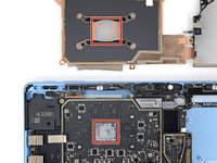
Use the flat end of a spudger to pry up the left and right edges of the thermal module, near where the copper heat pipes bend.
-
-
-
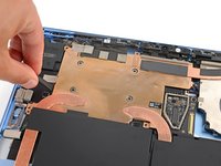
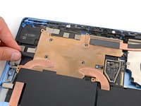
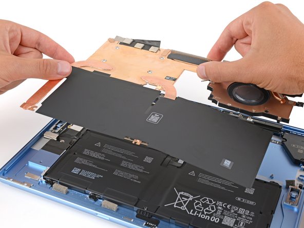
Use two hands to lift the thermal module straight up and remove it.
-
-
crwdns2935267:0crwdne2935267:0iFixit Thermal Paste$9.95
-
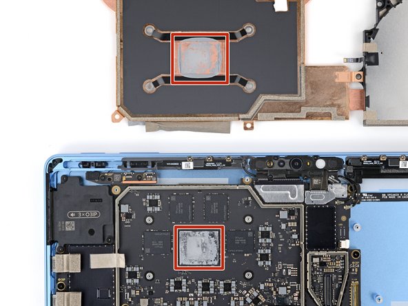
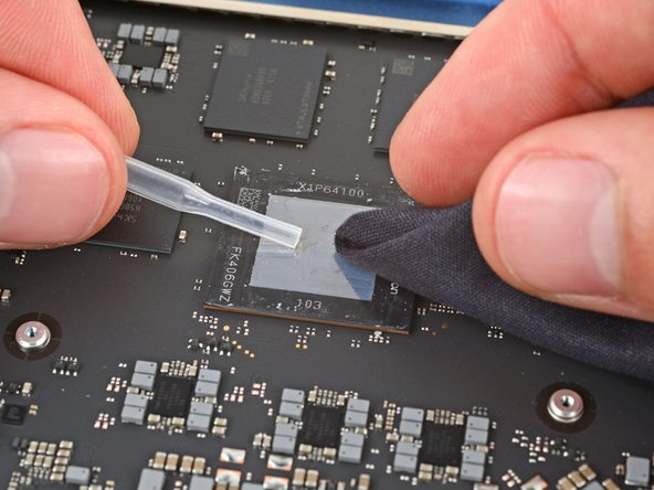
If you're installing a new thermal module, check if the bottom has thermal paste pre‑installed. If it does, do not apply thermal paste—you only need to clean the CPU.
-
Follow this guide to clean the thermal module and CPU and apply thermal paste.
-
-
-
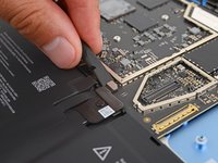
Use the flat end of a spudger to pry up the battery press connector from a short edge and disconnect it.
-
-
-
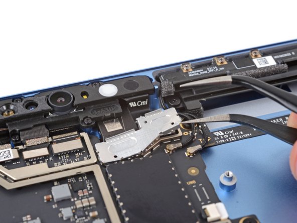
Insert an arm of a pair of angled tweezers in one of the gaps on the front sensor assembly metal cover, just below the front camera.
-
Use your tweezers to gently pry up and remove the cover.
-
-
-
Repeat the previous step to remove the metal shield just to the right of the previous one.
-
-
-
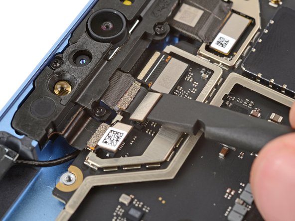
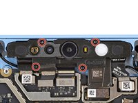
Use the point of a spudger to pry up and disconnect the left microphone press connector (the farthest left one below the front camera).
-
-
-
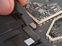
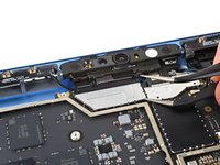
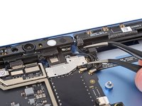
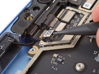
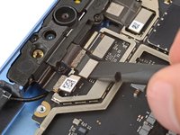
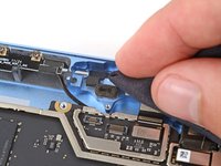
Use the flat end of a spudger to pry up and disconnect the Windows Hello sensor and rear camera press connectors.
-
-
-
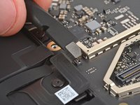
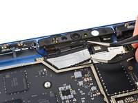
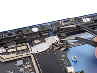
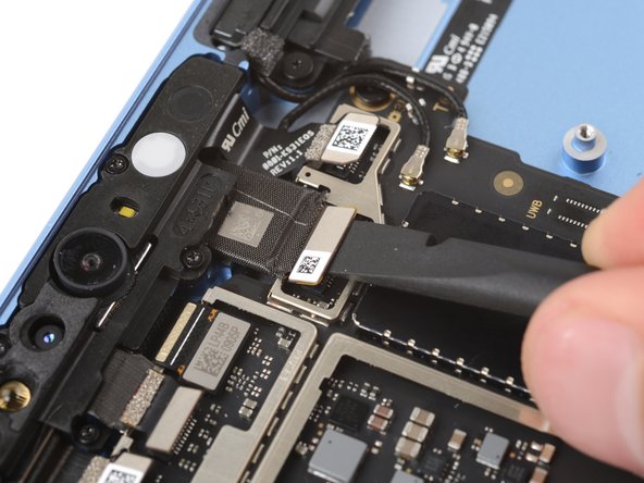
Use the point of a spudger to pry up the right microphone press connector (the farthest right one below the front camera) by its notched edge and disconnect it.
-
-
-
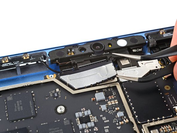
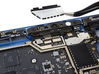
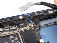
Use a Torx Plus 3IP screwdriver to remove the four 3.3 mm‑long screws securing the front sensor assembly.
-
-
-
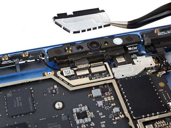
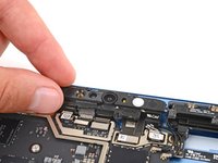
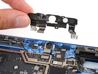
Lift the front sensor assembly straight up and remove it.
-
-
-
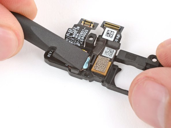
Check for any thermal paste on the frame (to the left of the front facing camera) and the corresponding spot on the back of the front sensor assembly.
-
Use the flat end of a spudger to scrape up any large chunks of paste.
-
Apply a few drops of isopropyl alcohol to a lint‑free cloth (or coffee filter) to clean up the area.
-
Allow the isopropyl alcohol to dry completely before continuing.
-
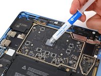
Apply a very small amount of thermal putty or viscous thermal paste where the old paste was on the frame.
-
-
-
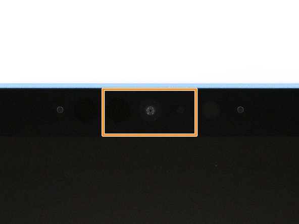
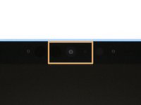
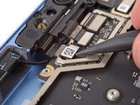
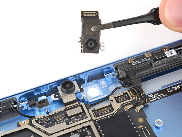
Use a Torx Plus 3IP screwdriver to remove the two 2 mm‑long screws securing the rear camera.
-
-
-
Lift and remove the rear camera.
-
Check your replacement camera for any liners or lens caps. If there are any, remove them.
-
Insert the camera lens down into its recess so the cutouts on its edges go over their posts on the frame.
-


To reassemble your device, follow these instructions in reverse order.
Take your e-waste to an R2 or e-Stewards certified recycler.
Repair didn’t go as planned? Try some basic troubleshooting, or ask our Answers community for help.
To reassemble your device, follow these instructions in reverse order.
Take your e-waste to an R2 or e-Stewards certified recycler.
Repair didn’t go as planned? Try some basic troubleshooting, or ask our Answers community for help.

