crwdns2915892:0crwdne2915892:0
When "Ink Absorber Full" or "Ink Absorber Near Full" appears on your printer screen, it's time to replace the Flushing Box (and/or the Ink Absorber Box).
Given the difficulty of this repair, it might be advisable to replace the Ink Absorber Box first, see if that solves the problem, and then replace the Flushing Box if that doesn't work, even though it will save time to do both at once.
crwdns2942213:0crwdne2942213:0
-
-
Open the front access door and remove any cards or cables present. Close the access door.
-
Remove the paper tray.
-
Remove the ink cartridges.
-
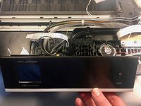
Open the printer cover using the finger holds on the sides.
-
Unplug and remove any cords present under the cover.
-
Remove the LAN port and EXT port caps (if present).
-
-
-
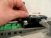
While holding the cover with one hand, pull the hook on the back of the support damper, then remove the damper from the cover.
-
Remove the damper from the support.
-
Turn the support upright and pull it straight out of the printer.
-
-
-
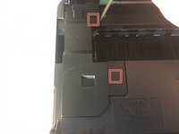
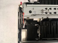
Use your finger or a spudger to unhook the two tabs on the right side of the harness cover by levering it up.
-
Remove the harness cover. There are two tabs on the left side that you have to wiggle free, and one on the front.
-
-
-
Remove the 6 mm Phillips #2 screw from the grounding wire of the ADF motor harness.
-
-
-
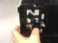
In the proceeding steps, you will disconnect the following cables:
-
CIS flat cable
-
Scanner motor harness
-
ADF motor harness
-
Document detection/document scanning position sensor harness
-
-
-
Pull the CIS flat cable out of its socket.
-
-
-
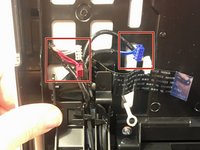
Pull the scanner motor harness out of its socket.
-
-
-
Pull the ADF motor harness out of its socket.
-
-
-
Pull the document detection/document scanning position sensor harness out of its sockets.
-
-
-
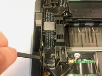
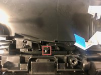
Insert a spudger between the scanner harness holder and frame to release the tab. There is a second tab on the opposite side.
-
Lift the scanner harness holder out of its frame.
-
-
-
Push on the tab to secure the scanner harness holder to the scanner cover.
-
De-route the document detection/document scanning position sensor harness and the ADF motor harness from the scanner harness holder.
-
-
-
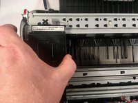
Using both hands, pull the scanner cover to the rear while holding it vertically, then lift it off of the printer.
-
-
-
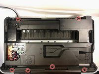
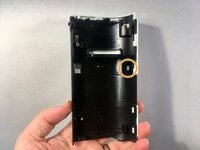
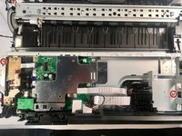
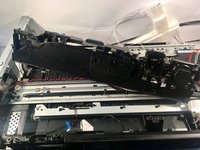
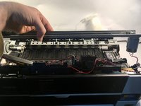
Remove the six 12 mm Phillips #2 screws securing the upper cover to the printer.
-
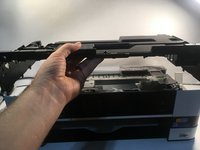
Pull off the upper cover.
-
-
-
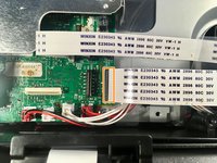
Remove the ink absorber full sensor from its socket.
-
De-route the wiring from its harness.
-
-
-
-
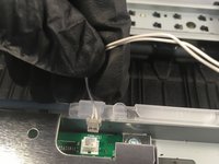
Unclip the ink absorber from the harness by pulling it up and to the right.
-
-
-
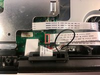
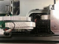
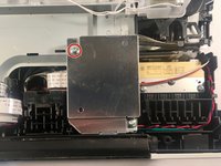
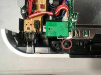
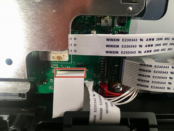
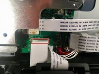
Remove the MJ PCB flat cable.
-
De-route the MJ PCB flat cable.
-
-
-
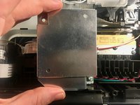
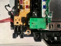
Remove the 6 mm Phillips #2 screw securing the MJ shield.
-
Remove the MJ shield.
-
-
-
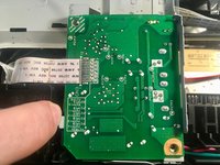
Remove the 6 mm Phillips #2 screw securing the MJ PCB assembly.
-
-
-
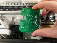
Pull back on the MJ PCB assembly release tab.
-
Remove the MJ PCB assembly.
-
-
-
Release the upper hook on the front cover.
-
Pry the front cover off. Note the tab on the left side of the cover.
-
-
-
Open the media module cover.
-
Release the two hooks holding the inner media module cover to the printer.
-
Remove the inner media module cover.
-
-
-
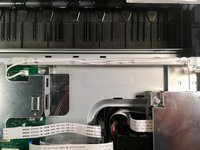
Remove the power supply PCB harness from the main PCB assembly and de-route it from the main PCB frame.
-
-
-
Remove the following wiring harnesses from the sensor relay PCB assembly, and de-route them from the main PCB frame:
-
Paper feed encoder sensor harness
-
Switchback sensor harness
-
-
-
Remove the following wiring harnesses from the main PCB assembly and de-route them from the main PCB frame:
-
Paper feed motor harness
-
Carriage motor harness
-
-
-
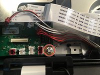
Remove the control panel flat cable.
-
Remove the ink refill sensor flat cable.
-
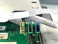
Remove the following cables:
-
Carriage PCB flat cable 1
-
Carriage PCB flat cable 2
-
Carriage PCB flat cable 3
-
-
-
Remove the following wiring harnesses attached to the main PCB frame:
-
Speaker harness
-
Ink cover sensor harness
-
Purge cam sensor harness
-
Registration sensor harness
-
-
-
Remove the 6 mm Phillips #2 screw securing the control panel grounding wire.
-
-
-
Remove two 10 mm Phillips #2 screws securing the main PCB frame.
-
Remove the final 6 mm Phillips #2 screw securing the main PCB frame.
-
-
-
Remove the 6 mm Phillips #2 screw securing the FG wire.
-
Unhook the tab of the clear plastic wiring holder.
-
Remove the main PCB frame.
Beim Zusammenbau ist das grüne Massekabel etwas zu kurz, um es mit den anderen, dünneren Leitungen in die Lasche der Kunststofffolie zu legen
-
-
-
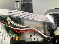
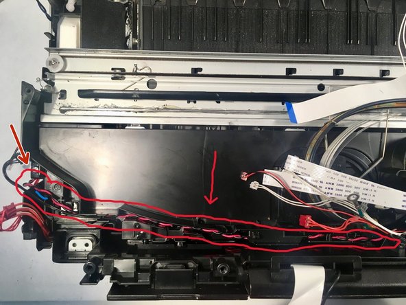
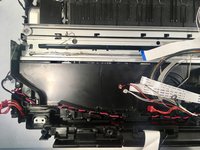
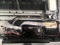
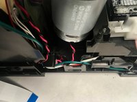
De-route the switchback sensor harness (black) and the paper feed motor harness (red and black) from the left side of the tube support plate.
-
De-route the speaker harness (red and black), purge cam sensor harness (white, three-wire), registration sensor harness (orange), ink cover sensor harness (white, two-wire), carriage motor harness (red and black), and FG wire (green) from the right side of the tube support plate.
-
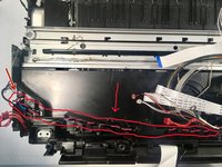
De-route the ink refill sensor flat cable from the tube support plate.
-
-
-
Remove the left 10 mm Phillips #2 screw holding down the tube support plate.
-
Remove the center 10 mm Phillips #2 screw holding down the tube support plate.
-
Remove the right 10 mm Phillips #2 screw holding down the tube support plate.
-
-
-
Tilt open the control panel to release the tilt hook stopper.
-
Release the retaining tab with your finger or a metal spudger.
-
Remove the tube support plate.
-
-
-
Open the jam clear cover.
-
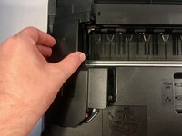
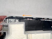
Push the lower right side cover in the direction of the arrow to release its hooks from the printer. A metal spudger may be of use here.
-
Pull the lower right side cover to the rear to release its hooks and remove it from the printer. Again, using a metal spudger to pry it to the rear may be useful.
-
-
-
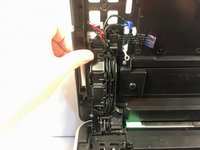
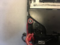
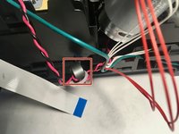
De-route the FG wire (green), the purge cam sensor harness (white), and the registration sensor harness (orange) from the right side of the machine.
-
Remove the magnet attached to the carriage motor harness (red and black) from its slot.
-
-
-
Remove the left carriage frame spring by pulling back on the tab on the bottom.
-
-
-
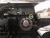
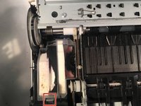
Turn the paper feed roller gear in the direction of the arrow until the head stopper of the maintenance unit clicks.
-
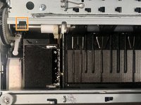
Slide the head/carriage unit to the removal slot position at the far left. Don't remove it yet.
-
This is the removal slot.
-
-
-
Remove the right carriage frame spring.
-
-
-
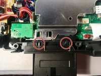
Remove the two 10 mm Phillips #2 screws holding down the carriage frame assembly.
-
-
-
Lift the carriage frame assembly out of the printer, making sure to keep the head/carriage unit over its release slots.
-
-
-
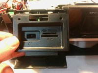
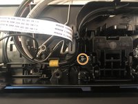
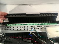
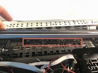
Remove the flushing base by lifting it straight upwards.
-
The flushing base, removed.
Kann man die base Flush nachkaufen? Also das schwarze teil/ schaumstoff??
-
-
-
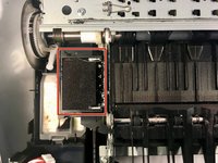
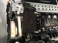
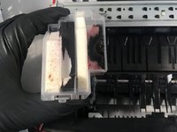
Remove the flushing box by disengaging the front hook, then tilting it up to disengage the rear hook.
-
The flushing box, removed.
Bonsoir j'ai fait la manip pour rebooter l'imprimante mais mon message fermez le capot du scanner reste allumé grrr j'ai changé les tampons d'Encre absorbeur ce serait dommage que jabandonne cette imprimante juste pour ce message erreur si quelqu'un a une piste
-


To reassemble your device, follow these instructions in reverse order. If you haven’t already, it’s recommended that you also replace the ink absorber box during reassembly.
Screw torques from the service manual have been included if you happen to have a torque screwdriver, but don’t worry about them if you don’t.
After reassembly, follow the following steps to reset the purge count in order to clear the “Ink Absorber Full” error:
- Plug the printer in and turn it on.
- Press the Home button (the house icon) on the front of the printer until the Maintenance Mode screen appears (approximately five seconds).
- Hold down the blank button at the bottom of the screen until a number keypad appears on the screen (approximately two seconds).
- Press *, 2, 8, 6 and 4 (you can use the onscreen keypad or the printer’s built-in keypad for this). The printer will beep and MAINTENANCE will appear on the screen.
- Press 8 and 0.
- Press the down arrow repeatedly until PURGE: (or FLUSHING:) appears on the screen.
- Press 2, 7, 8 and 3. The printer will beep and MAINTENANCE will again appear on the screen.
- Press 9 twice to exit maintenance mode and reboot the printer. You can also use this to start over if you make an error.
crwdns2935221:0crwdne2935221:0
crwdns2935229:020crwdne2935229:0
crwdns2915084:0crwdne2915084:0

Syler Solutions crwdns2935289:0Syler Solutionscrwdne2935289:0
Business
crwdns2934841:01crwdne2934841:0
crwdns2935297:012crwdne2935297:0
crwdns2947412:014crwdne2947412:0
Hi there.
Great guide - although some pics of re-assembly and re-routing of the cables that were de-routed would have been very helpful. I am a complete novice and I followed this guide to the letter. I was successful in installing both boxes and re-assembling the printer so that on my initial power up it showed a fully usable touchscreen. However I then had a problem where it would not detect (any of) the ink cartridges.
I thought it might have been a loose connection and went as far back as re-seating the connections on the main PCB frame. After that the touchscreen display just remained blank.
I can’t think what I could have screwed up in re-seating things. One step forward - two steps back !
If anyone reads this and has some idea I would appreciate any assistance.
Cheers
S
When fixing the tube support plate be careful to have the blck cables of the switchback sensor harness pulled out as far as possible, it will be stuck under the plate and too short to plug it in again.
Bernd
bonjour.
Excellent guide -j’ai le MFC-J6520dw il est tout a fait compatible.mais j’ai un autre probleme “please dl rom” j’ai meme mis a jour le firmware.bonne journée et merci
Mokhtaaar j
m
Désolé, je ne peux pas vous aider avec le problème "dl rom". Peut-être demander dans les forums? (Ceci provient de Google Translate; j'espère que cela a du sens.)
Calion -
Great guide.
Take care when replacing the 'carriage frame assembly' as I had continual paper jams on initial reassembly. I completed another tear down to get at this part and re-seat it properly (just more jiggling until satisfied that it was well seated). All good then. Also, I don't believe I had to carry out the second part of point no. 11.
Valuable guideline.
I have replaced the ink absorber and the „Spülkammer“. After the re-assembling and the initial power-on, I get the error message „paper cartridge noot detected. Replaced the paper cartridge in the device, again.“ I dis-assembled step-by-step the printer again to double-check all the cables and their connectors. Without success.
Any hints, where I can find the root cause?
Within the chapters of this guideline I don‘t find the right advice, unfortunately.
Linked in the main page for this device is the service manual. It may help.
Calion -
Worked great for my MFC-J$%10DW - thank you. My after-thoughts:
1. I agree with the comment above: "When fixing the tube support plate be careful to have the blck cables of the switchback sensor harness pulled out as far as possible, it will be stuck under the plate and too short to plug it in again."
2. I also agree that the second part of step 11 (cable derouting) is not required.
3. When re-assembling and re-routing the cables, I studied the author's photos to supplement my memory. Afterwards I discovered that the service manual (linked from MFC-J4410DW ) contains detailed diagrams of how to route the cables.
(Continued as I am about to run out of character count.)
Please feel free to edit the Guide.
Calion -
(continued from above)
4. "Conclusion" step 4: My printer was in "ink absorber full" error mode before I replaced the ink absorber and flushing box, and instead of "MAINTENANCE" it showed "Machine Error 46". I needed a bit of extra help from the service manual at this point. After entering "80", the printer is in a mode where it displays individual items from the "Equipment log" at the top of the screen. To see the "down arrow" on the screen you have to press ">>" button twice. The down arrow then appears as the top left button on the display. You then press this about 35 or so times. Each time the display shows a new item from the log. When the display shows PURGE:[number] you then enter 2783 to reset that counter to zero. You are now at the beginning of conclusion step 5, so you enter 80 again, press the down arrow a few more times than before until the display shows FLSBK:[number] and then enter 2783 to reset the black flush count. This seemed to reset the colour flush count too.
Hallo,
Danke für die Super Anleitung.
Oben in der Beschreibung steht, dass es nicht unbedingt notwendig sein muss, die Spülkammer auch auszutauschen.
Woher weiß ich denn, ob die Spülkammer getauscht werden muss? Oder ist es empfehlenswert immer beides zu tauschen?
Die Fehlermeldung bezieht sich ja eigentlich auf den Absorber.
Und: die Links zu den Ersatzteilen funktionieren zumindest bei mir nicht.
The only help I can offer is that the service manual is on the main page for this product.
Calion -
Klasse Anleitung.
Wird es in absehbarer Zeit auch Ersatzteile und eine Anleitung für den Brother MFC-J4340 geben?
Wann wird eigentlich Tinte in die Spülkammer und wann in die Absorberbox geleitet?
The manual for this model is on the product page.
Calion -
Ersatzteil findest Du hier:
https://www.druckerpatronen-und-toner.de...
Thomas Baumann - crwdns2934203:0crwdne2934203:0
Thanks! Added to Ink absorber box.
Calion -