crwdns2915892:0crwdne2915892:0
Use this guide to replace the vibration motor in your LG V20.
crwdns2942213:0crwdne2942213:0
-
-
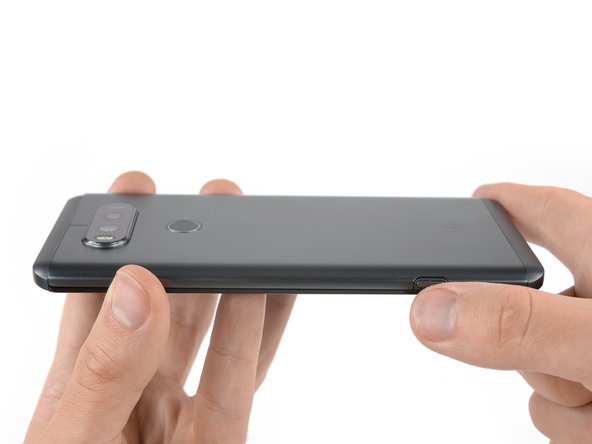
Press the button on the lower right side of the LG V20 to open the clamp that holds the back cover on the back side of the phone.
-
Remove the back cover.
-
-
-
Insert a spudger or your fingernail under the battery at the small recess on the lower edge.
-
Be careful not to deform or puncture the battery.
-
Pry up and remove the battery.
-
-
-
Remove the sixteen 4mm Phillips #00 screws attaching the back cover to the motherboard.
-
-
-
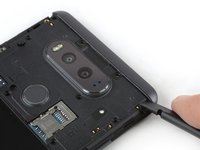
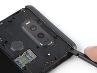
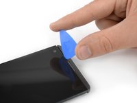
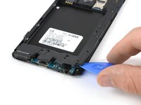
Use the flat end of a spudger and apply pressure to one of the corners of the frame section until you create a small gap.
-
-
-
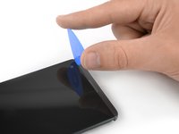
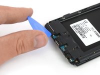
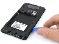
Flip the phone and insert an opening pick in the gap you created.
-
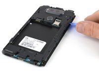
Slide the opening pick along the gap until the frame section pops out of its plastic clamps.
People on Reddit are reporting that the V20's antennas are contained in this top piece, and removing it too forcefully can damage the 2G antenna's contacts, resulting in a loss of ability to make calls. Details and a suggested fix if this happens to you:
-
-
-
-
Remove the frame section.
-
Repeat this procedure with the frame section on the other end of the phone.
-
-
-
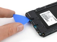
The loudspeaker is attached to the cover of the motherboard. Use an opening pick to pry it up.
Be very careful with prying up the speaker or else it will break the connection to the cover.
-
-
-
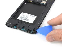
Use an opening pick to pry up the motherboard cover at the right corner at the bottom of your phone until it pops out of the plastic clamp.
Bonjour, en placant le médiator à l’intérieur de l’emplacement de la batterie le démontage est plus facile de l’intérieur vers l’extérieur…
Merci pour l’info!
In English: it is easier work your way around the inside of the battery compartment rather than around the outside. Also, the clip below the power button (i.e., top of the battery compartment) will release the whole top edge.
-
-
-
Slide the opening pick along the mid frame and flip it sideways to open the plastic clamps holding the motherboard cover in its place.
-
-
crwdns2935267:0crwdne2935267:0Tweezers$4.99
-
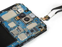
Use the flat end of a spudger to disconnect the front camera flex cable.
-
Use a pair of tweezers to carefully remove the front facing camera. Be careful to only grip the body of the camera, as the top is the sensor pcb and is only held on with glue (removal will ruin the sensor).
-
-
crwdns2935267:0crwdne2935267:0Tweezers$4.99
-
Use the flat end of a spudger to disconnect the flex cable of the left rear camera.
-
The second rear camera will come out with the motherboard since it is connected on the other side.
-
You can leave the front facing camera in its place as long as you're careful while removing the motherboard assembly. However if you feel uncertain, carefully remove it with a pair of tweezers.
Anyone have a picture of the back of the board by the charge port
-
-
-
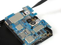
Disconnect the display flex cable with the flat end of a spudger.
-
-
-
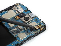
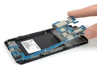
Use the pointed end of a spudger to lift up the motherboard assembly until you can get a good grip.
-
Carefully lift up the motherboard assembly and remove it.
Be very careful handling motherboard. The numerous spring-type contact points can be easily bent.
-
-
crwdns2935267:0crwdne2935267:0Tweezers$4.99
-
Use a pair of tweezers to remove the vibration motor.
Does the adhesive holding the motor need to be replaced? What kind is needed?
Hi databasebloat,
usually the adhesive can be reused. In case you want to replace it anyway, you can use thin double sided tape and cut it into small pieces or a shape similar to the old adhesive.
-


To reassemble your device, follow these instructions in reverse order.
To reassemble your device, follow these instructions in reverse order.
crwdns2935221:0crwdne2935221:0
crwdns2935229:04crwdne2935229:0


crwdns2947412:02crwdne2947412:0
When I dug down to the motor, I found it wasn’t going to be that easy to pull it out.
Instead, I checked that it actually worked by touching its contacts carefully to a 1.5v AA battery. It turns out that the spring contacts on the motor were a little too compressed, so I stretched them with tweezers, and didn’t need to replace the motor: all works.
my motor also stopped working. after taking it apart i noticed the gold contacts on the PCB were hardly rubbed. connected a 2.5 v PSU to the motor. works! also just ended up stretching the spring. Also added some NT-H1 thermal paste to the area with the thermal pad and the other can beside it. Thermal throttling was reduced significantly.