crwdns2915892:0crwdne2915892:0
This guide shows how to use your multimeter to measure beyond voltage, resistance, and continuity. If you've mastered the basics and you're ready to learn more, this guide is for you!
This guide is written with the iFixit multimeter in mind. If you have a different multimeter, you may not have the same functionality and there may be slight operational differences. The fundamental concepts, however, will still be applicable.
-
 crwdns2952109:0crwdne2952109:0
-
-
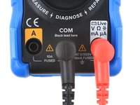
Plug the black lead into the COM port. Plug the red lead into the A port (the left port on the iFixit multimeter).
-
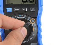
Turn the function dial to the amp A mode. If you're measuring Alternating Current (AC), press the blue select button to switch to AC mode.
-
-
-
Power down the circuit you're measuring.
-
Choose the point where you want to measure the current. You'll need to break the circuit at that point. This may mean snipping a wire, disconnecting a connector, or removing a jumper wire.
-
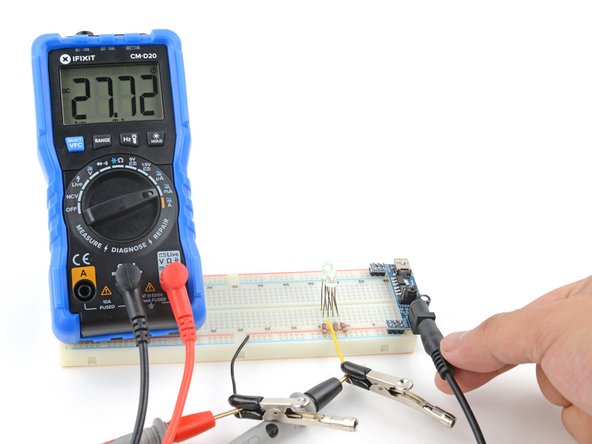
Connect the multimeter in-line with the circuit by touching the probes to the ends of the broken circuit. If possible, use alligator clips to hold the probes to the ends.
-
Power on the circuit and make your measurement.
-
-
-
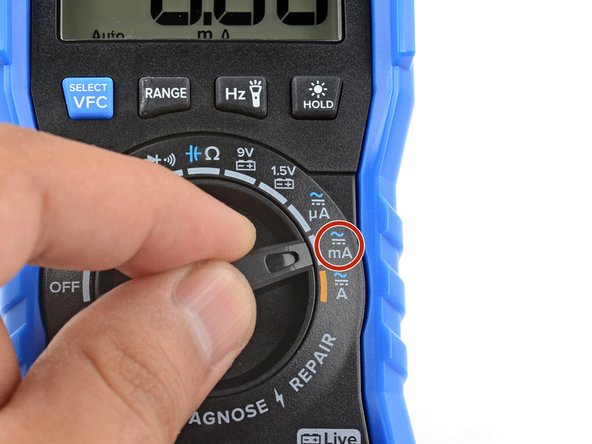
Plug the black lead into the COM port. Plug the red lead into the mA port (the right port on the iFixit multimeter).
-
Turn the function dial to the milliamp mA mode. If you're measuring Alternating Current (AC), press the blue select button to switch to AC mode.
-
You can also measure in the microamp μA mode if you know you're measuring minute amounts of current. This changes the measurement range and gives you more precision at the μA range. Even if you exceed that range, it won't damage your multimeter—as long as you don't exceed the port limit (600mA).
-
-
-
Power down the circuit you're measuring.
-
Choose the point where you want to measure the current. You'll need to break the circuit at that point. This may mean snipping a wire, disconnecting a connector, or removing a connecting jumper wire.
-
Connect the multimeter in-line with the circuit by touching the probes to the ends of the broken circuit. If possible, use alligator clips to hold the probes to the ends.
-
Power on the circuit and make your measurement.
-
-
-
-
Plug the black lead into the COM port. Plug the red lead into the right port.
-
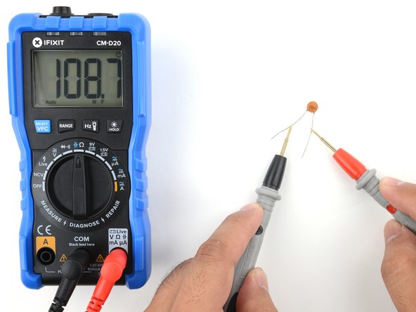
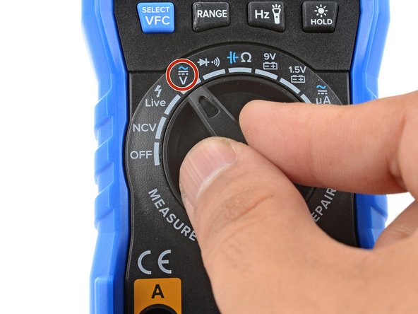
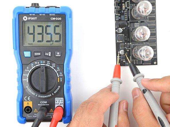
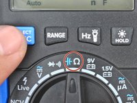
Turn the function dial to the resistance/capacitance mode and press the blue select button to toggle on the capacitance mode.
-
Power down the circuit you're measuring, if you're measuring the capacitor while it's still connected to the circuit.
-
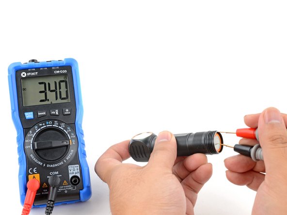
Touch the probes to each end of the capacitor to make a measurement.
-
-
-
Plug the black lead into the COM port. Plug the red lead into the right port.
-
Power down the circuit you're measuring, if you're measuring the capacitor while it's still connected to the circuit.
-
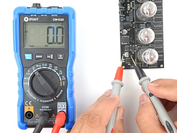
Turn the function dial to the DC volt mode.
-
Carefully touch the probes to the capacitor's leads/pads to measure voltage. Treat the circuit as a live circuit and be careful not to touch anything else with your probes.
-
-
-
Turn the function dial to the resistance/capacitance mode and press the blue select button to toggle on the capacitance mode.
-
Touch the probes to each end of the capacitor to make a measurement.
-
-
-
Plug the black lead into the COM port. Plug the red lead into the right port.
-
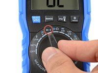
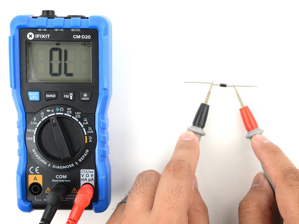
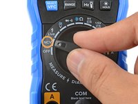
Turn the function dial to the diode/continuity mode.
-
-
-
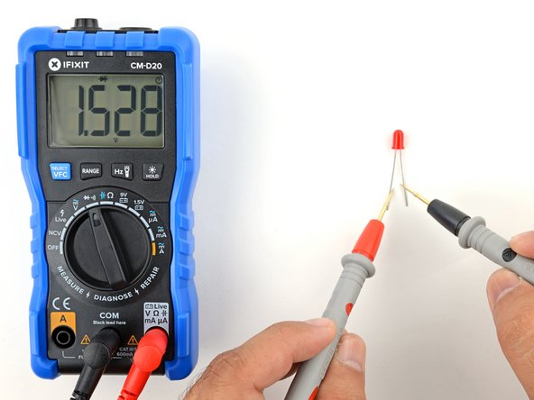
Touch the red probe to the anode, "input", or unmarked end of the diode. If you're testing an LED, touch the longer lead.
-
Touch the black probe to the cathode, "output", or marked end of the diode. If you're testing an LED, touch the shorter lead (or the lead next to the flat side of the LED).
-
Reverse the probes so they touch the opposite ends of the diode.
-
-
-
Plug the black lead into the COM port. Plug the red lead into the right port.
-
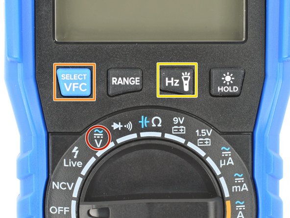
Switch the multimeter to the AC Hz mode:
-
Turn the function dial to the Volts mode.
-
Press the blue Select button to switch to AC volts.
-
Press the Hz button to toggle the frequency measurement mode.
-
-
-
Touch the probes across the AC source and make a measurement.
-
To toggle the VCF mode on/off while you're measuring AC frequency, hold the blue Select/VFC button for two seconds.
-
-
-
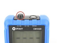
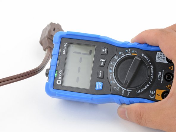
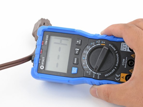
The NCV sensor sits inside the plastic nub at the top of the iFixit multimeter. The metal strip inside acts as an "antenna" that detects the electromagnetic field generated by an AC source. This field gets stronger the closer it is to the source.
-
To use the NCV function, turn the function dial to the NCV mode.
-
-
-
Move the NCV sensor so that it's close to the wire or circuit. If there's live AC, the multimeter will begin beeping and the top indicator LEDs will light up.
-
-
-
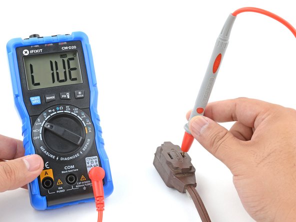
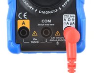
Plug a probe into the right-most port of the multimeter.
-
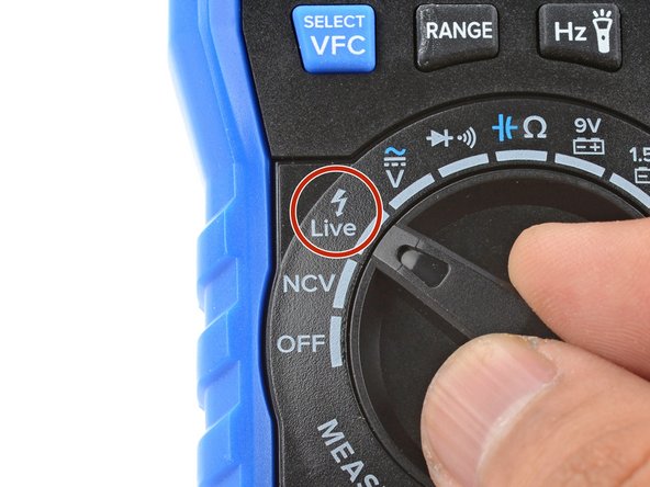
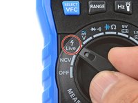
Turn the function dial to the Live mode.
-
Touch the probe to the wire you want to test.
-


For more electronics skills guides, click here.
crwdns2935221:0crwdne2935221:0
crwdns2935229:022crwdne2935229:0


crwdns2947410:01crwdne2947410:0
Good basic meter use guide for those new to meter use.
rickwag - crwdns2934203:0crwdne2934203:0 crwdns2950251:0crwdne2950251:0