crwdns2915892:0crwdne2915892:0
This repair guide was authored by the iFixit staff and hasn’t been endorsed by Google. Learn more about our repair guides here.
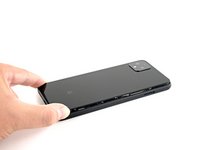
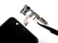
Use this guide to remove or replace the rear-facing cameras on your Google Pixel 4 XL.
Caution: Google warns that disassembly of the front laser assembly could result in hazardous exposure to invisible infrared laser emissions. Read their safety warnings here.
crwdns2942213:0crwdne2942213:0
-
-
Insert a SIM eject tool, bit, or a straightened paper clip into the small hole on the SIM card tray on the left edge of the phone.
-
Press firmly to eject the tray.
-
Remove the SIM card tray.
-
-
-
Prepare an iOpener and apply it to the bottom edge of the back panel for one minute.
I found 2 minutes works best per side. Great Guide btw, thank you for being a strong leader in the fight for right to repair.
-
-
-
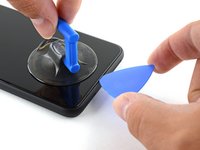
Apply a suction cup to the heated edge of the back panel by pressing down on it to create suction, as close to the edge as possible.
-
-
-
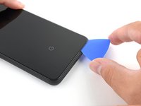
Pull up on the suction cup with strong, steady force to create a gap between the back panel and the frame.
-
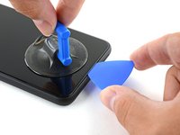
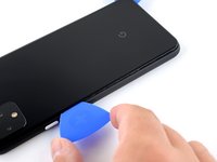
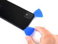
Insert the point of an opening pick into the gap.
-
-
-
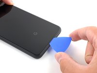
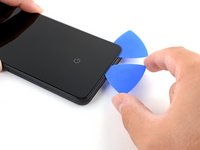
Slide the opening pick across the bottom towards the left corner to slice the adhesive.
-
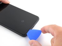
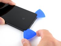
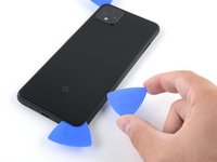
With the pick still inserted, slide it from the bottom left corner over to the bottom right corner to completely slice the bottom side adhesive.
-
Leave the pick inserted in the bottom right corner to prevent the adhesive from re-sealing.
-
-
-
Prepare an iOpener and apply it on the left edge of the phone for one minute.
-
-
-
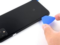
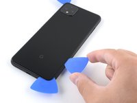
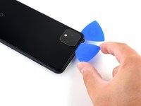
Insert a second opening pick underneath the back panel directly over the charge port.
-
Slide the opening pick to the bottom left corner of the phone.
-
-
-
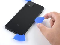
Slide the opening pick around the bottom left corner and across the left side of the phone to slice the adhesive.
-
Stop when you reach the top left corner, near the camera, and leave the pick inserted.
-
-
-
Prepare an iOpener and apply it on the right edge of the phone for one minute.
-
-
-
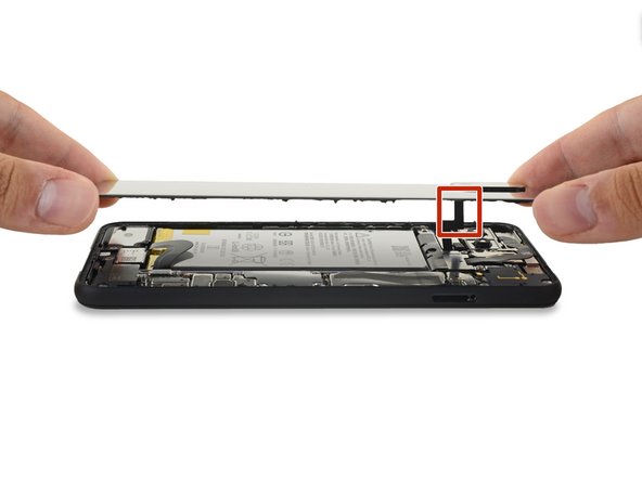
With the first two opening picks still in place, insert a third pick on the lower part of the righthand side.
-
Slide the opening pick up towards the top of the phone, slicing the right side's adhesive.
-
Stop when you reach the top right corner, and leave the pick inserted.
Be careful when slicing the right side's adhesive. The contacts for the wireless charging pad are close to the edge and can easily be bent with the opening pick.
-
-
-
Slide the third opening pick around the top right corner and across the top side of the phone, slicing the final strip of adhesive.
-
-
-
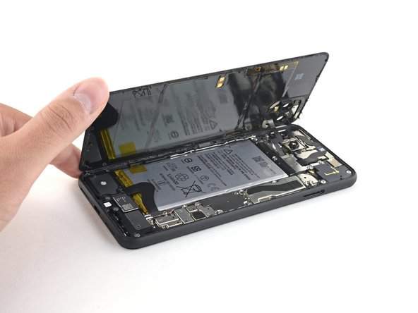
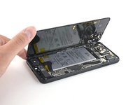
Once you have sliced around the perimeter of the phone, carefully lift the right edge of the back cover, opening it like a book.
-
Do not try to pull the panel all the way off yet, as it is still connected to the phone.
-
-
-
Continue swinging open the back panel until you can rest it on the left edge the phone, being careful not to put any stress on the attached ribbon cable.
“and test all functions before sealing it up.”
Pretty sure I wont be sealing this up for a few hours, might be worth removing this part of the sentence as it’s confusing…
Geoff B: These are good instructions. Any technician worth his or her salt will test the device for functionality before sealing it up. That’s why it reads, “During reassembly…and test all functions before sealing it up.” Not confusing if you read and comprehend the full pin.
No instructions on how to fit new sticky gasket before assembly. Removing old adhesive was a messy business, I used IPA on a cotton bud and removed as much as possible with flat end of spudger and kitchen paper.
-
-
crwdns2935267:0crwdne2935267:0Magnetic Project Mat$19.95
-
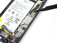
Remove the four T3 Torx screws securing the battery connector shield:
-
One 1.8 mm screw
-
One 4.1 mm screw
-
One 4.4 mm shouldered screw
-
One 4.0 mm shouldered screw
Anyone know the thread size of the 1.8mm screw mentioned here? Mine went missing, and I need to get a replacement. I've got a bunch of tiny screw kits, but none of them have fit!
-
-
-
crwdns2935267:0crwdne2935267:0Tweezers$4.99
-
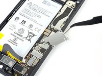
Use a pair of tweezers to remove the battery connector shield.
-
-
-
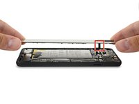
Using the pointed end of a spudger, pry the battery connector straight up from the motherboard to disconnect the battery.
I had the piece from the cable break off inside the connector. How would I go about getting it out
What are the 5 copper dots under the battery connector for.
When you reattach the connector to the motherboard this is a good time to power up and check basic functionality temporarily. Even though it had appeared it was correctly lined, my camera was not functional, in particular the switch button from the rear to the front camera, I was stuck in selfie mode. Then I was getting a message on the screen, possible hardware or software issues. Once I reattached the connecter (several times) until it was correctly inlined, the error went away and I was able to switch from the rear and front cameras.
That was a good call! Thanks!
Esther -
-
-
-
Using the flat end of a spudger, gently fold the battery cable over so it doesn't accidentally make contact during the rest of your repairs.
-
-
-
Use a T3 Torx driver to remove the two 4.1 mm screws securing the back panel connector cover.
Wouldn’t it make more sense to use the same (orange) color circles as the other 4.1mm screw?
Maybe Google did it to avoid exchange in the models where they differ
-
-
-
Use a pair of tweezers to remove the back panel connector cover.
-
-
-
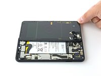
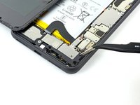
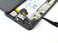
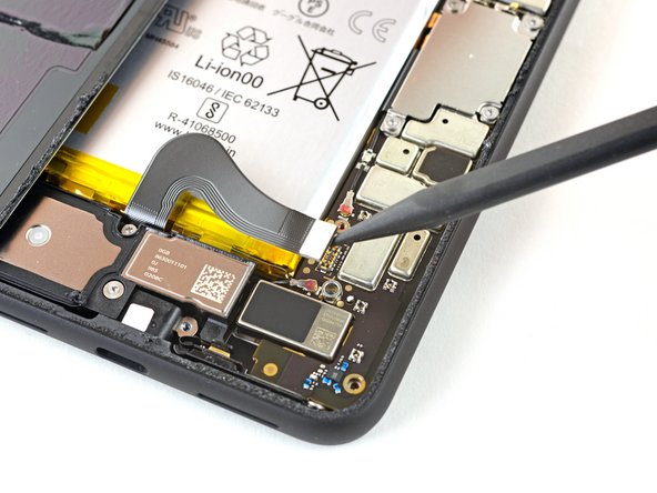
Using the pointed end of a spudger, pry up and disconnect the back panel connector.
During reassembly, make sure to firmly connect this back panel connector.
I had to hold the back panel close to the phone so that the connector stays connected, while putting back all the screws.
-
-
-
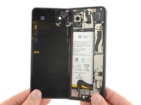
Remove the back panel.
REASSEMBLY ADHESIVE: This is the step during reassembly that you'll want to set the back glass adhesive strip on (before you reattach ribbons). Set the adhesive strip into the body of the phone with the red tabs down (toward the body of the phone, it will simply rest inside the lip of the phone body). Press the back glass onto the adhesive strip to set the strip onto the back glass, lift the back glass back out of the body of the phone. Next reattach the ribbons, test functions, reattach connector covers, peel red adhesive cover off of the adhesive (on the back glass) then set the back glass into the phone lip. This could have been explained far better but was skipped over and the generic adhesive instructions posted in the comments are useless for this.
There are also detailed instructions at answer 742532, "How do I apply new back panel adhesive on a Pixel 4xl?" (sorry it doesn't let me link directly). But it advises adhering the adhesive to the main frame first before the glass. I do notice a slight lip on the main frame on both sides, which seems less forgiving to align with than the glass, so I would imagine doing the frame first would be easier? I haven't done this yet myself, so would be interested in opinions.
Update: it appears the discrepancy is due to a difference between the third-party adhesives and the iFixit "genuine" one. The iFixit one is not mirror symmetric and must be adhered to the glass back first, though it has cutouts that avoid protrusions and facilitate this. The third-party one (I believe) has no such cutouts and thus must go on the frame first.
However, in trying to follow Michael's instructions, I could not get the adhesive and red tabs off the blue plastic without distorting the adhesive, and had to take the clear side off first. I ended up directly placing the adhesive onto the glass back, without the frame to help align (I posted my method in the above-mentioned answer 742532). The cutouts in the blue plastic seem to have been made with this in mind.
-
-
-
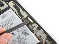
Gently pry back the battery adhesive pull tab to allow easier access to the screws underneath it.
-
-
-
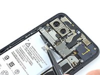
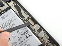
Remove the three T3 Torx screws securing the rear-facing camera connector cover:
-
One 2.7 mm screw
-
One 4.1 mm screw
-
One 4.2 mm screw
-
-
crwdns2935267:0crwdne2935267:0Tweezers$4.99
-
Use a pair of tweezers to remove the rear-facing camera connector cover.
-
-
-
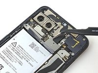
Remove the three T3 Torx screws securing the front-facing camera connector cover:
-
One 4.1 mm screw
-
One 4.0 mm shouldered screw
-
One 4.1 mm shouldered screw
-
-
-
Use a pair of tweezers to remove the front-facing camera connector cover.
-
-
-
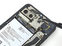
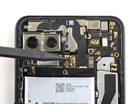
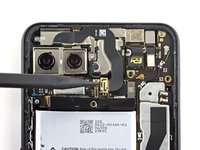
Using the pointed end of a spudger, pry the camera and sensor connectors straight up from the motherboard.
-
-
-
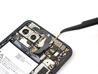
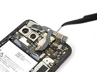
Disconnect the additional sensor connector.
-
-
-
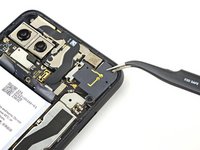
Remove the three T3 Torx screws securing the front camera and sensor assembly:
-
Two 2.7 mm screws
-
One 3.1 mm screw
-
-
-
Use a pair of tweezers to remove the front camera and sensor assembly.
Additional Sensor from Step 28 is held down with adhesive. Gently pry up on cable to remove sensor assembly.
After replacing the camera , the phone shows certificate expired for the face unlock. It would be nice to have the how to fix that here.
-
-
-
Use a T3 Torx driver to remove the four 3.5 mm screws securing the display connector cover.
-
-
crwdns2935267:0crwdne2935267:0Tweezers$4.99
-
Use a pair of tweezers to remove the display connector cover.
-
-
-
Use the flat end of a spudger to disconnect the display connector from the motherboard.
-
-
-
Use a T3 Torx driver to remove the 2.7 mm screw securing the motherboard to the frame.
-
-
-
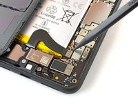
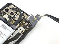
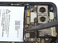
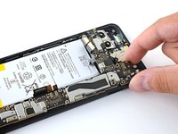
Use the pointed end of a spudger to disconnect the side buttons connector from the motherboard.
-
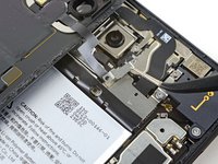
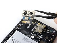
Disconnect the two rear-facing camera connectors from the motherboard.
The screw on the top left of the motherboard is out in this picture, but removal is not included in previous steps. It’s still visible in Step 30.
Thank you! Good catch. I’ve added a new step for removing that screw.
-
-
-
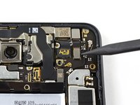
Disconnect the earpiece speaker connector from the motherboard.
-
-
-
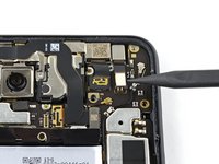
Disconnect the two grip sensor connectors from the motherboard.
-
Disconnect the charge port connector from the motherboard.
-
-
-
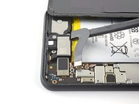
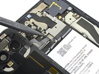
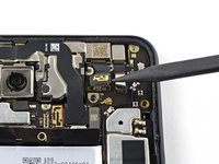
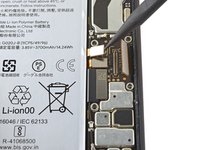
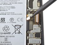
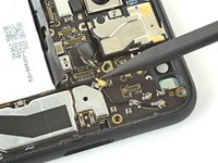
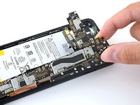
Use the pointed end of a spudger and pry up gently to unclip the top antenna connector from the motherboard.
-
Disconnect the bottom antenna connector.
-
-
-
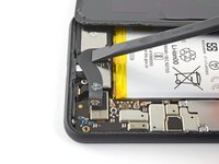
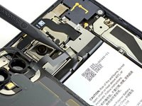
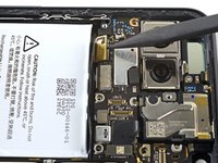
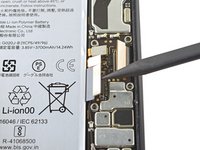
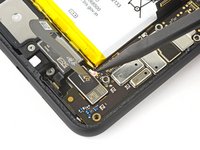
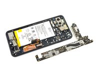
Using a spudger, pivot the top end of the motherboard up and out of the phone's frame.
-
-
-
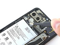
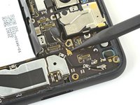
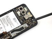
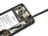
Slowly lift out the motherboard, being careful not to snag any ribbon cable connectors.
-
Completely remove the motherboard.
I was able to remove and replace the camera module without completely removing the motherboard from the body. It makes sense to do the disconnections so no cables are broken, but might not be worth completely removing the motherboard.
It seems Face ID is related to the combination of front camera and mainboard, so if possible, keep these together, for example, when switching the housing because of a broken screen.
-
-
crwdns2935267:0crwdne2935267:0Tweezers$4.99
-
Use a pair of tweezers to remove the rear-facing camera module.
-


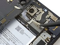


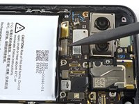


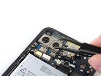
Compare your new replacement part to the original part—you may need to transfer remaining components or remove adhesive backings from the new part before installing.
To reassemble your device, follow the above steps in reverse order.
Take your e-waste to an R2 or e-Stewards certified recycler.
Repair didn’t go as planned? Try some basic troubleshooting, or ask our Answers community for help.
crwdns2935221:0crwdne2935221:0
crwdns2935229:04crwdne2935229:0


crwdns2947410:01crwdne2947410:0
Hi Sir,
I folllowed this instruction to replace my rear camera but when I assembled again, everything works fine but front camera cannot be detected and faceid not working. It show black screen when I flipped from rear to front camera, faceid show “ face enrollment was not completed?
I am carefull person. I flashed many stock firmwares again but it didn't work. Hope to get your help.
Many thanks.