crwdns2915892:0crwdne2915892:0
Use this guide to replace or upgrade the Mainboard in your Framework 16 Laptop.
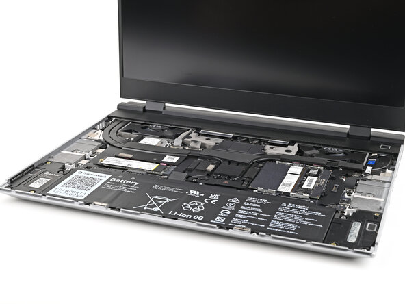
The Mainboard (aka motherboard) is responsible for the primary functions for your laptop. If you want to upgrade your processor, you'll need to replace the Mainboard.
Replacement Mainboards come with a pre-installed heatsink but don't come with pre-installed storage, memory, or Wi-Fi modules. This guide will show how to transfer them to your new Mainboard.
If you're running Windows:
- Make sure you back up your data.
- If you’re running a Pro version of Windows, follow these directions to suspend BitLocker.
- If you're running a Home version of Windows and have enabled Windows Device Encryption, you'll want to disable it. To disable it, press Win + I to open Settings and select Privacy & Security. Then, click on Device Encryption on the right panel and toggle the setting to Off.
- Find your product key or link your Windows license to a Microsoft account to make sure you can re‑activate Windows after the change.
Some photos in this guide may contain slight visual discrepancies, but they won't affect the procedure.
crwdns2942213:0crwdne2942213:0
-
-
Unplug all cables and fully shut down your laptop.
-
-
-
Close the laptop and flip it over.
-
-
-
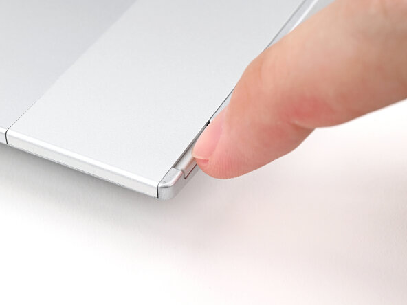
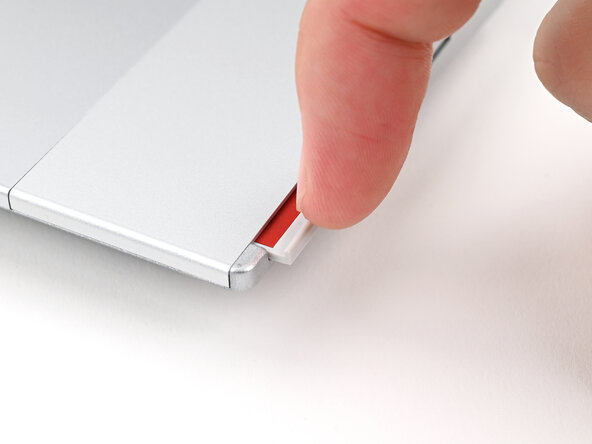
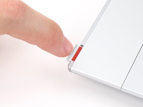
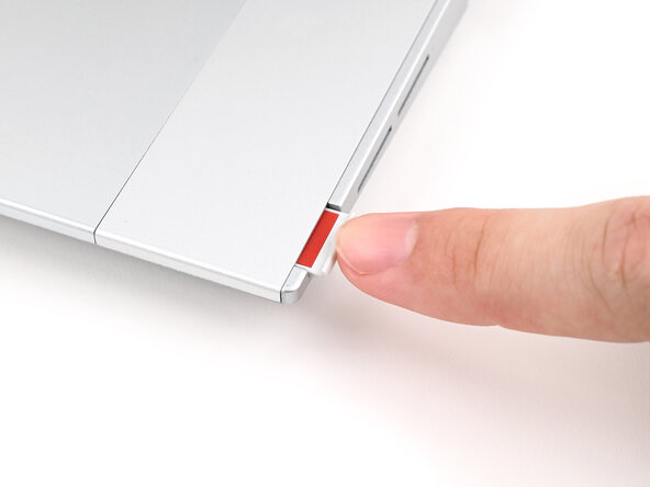
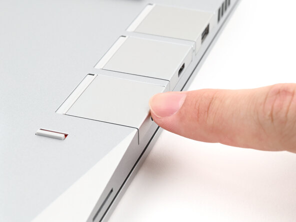
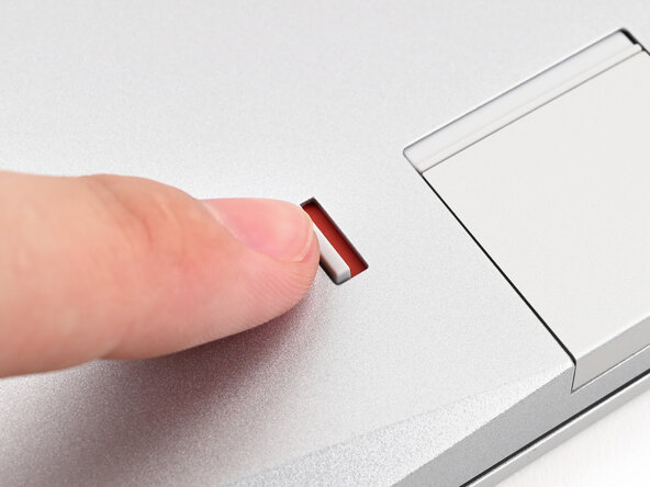
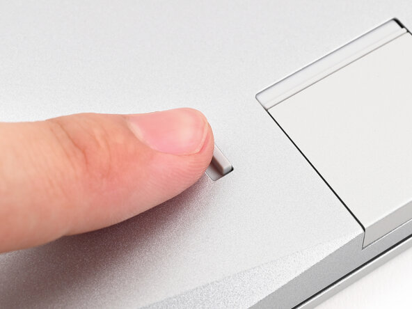
Use your finger to flip the Expansion Card latches into the unlocked position.
-
-
-
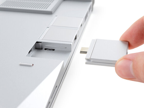
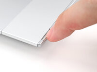
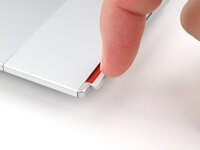
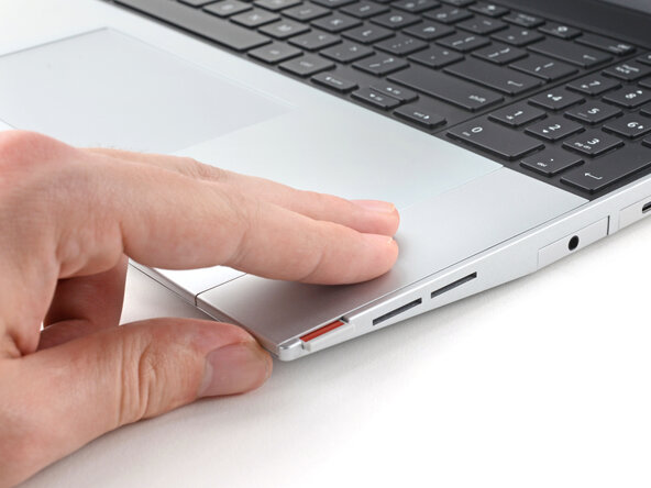
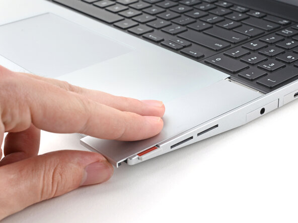
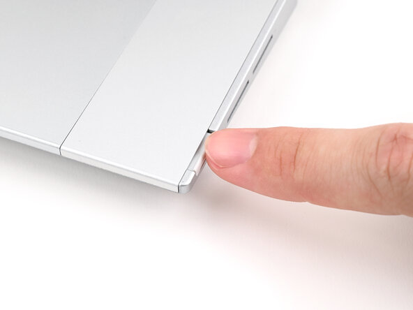
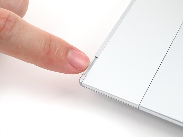
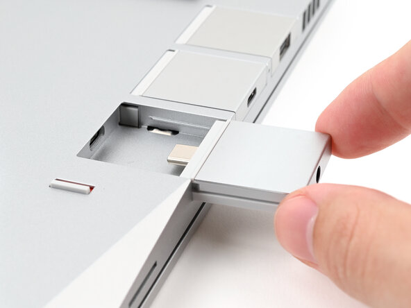
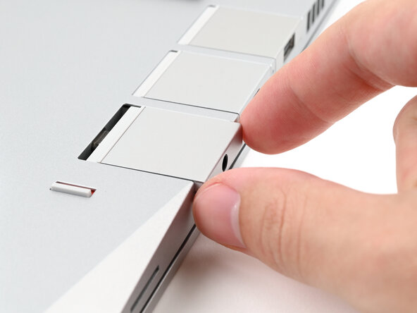
Grip the lip of the Expansion Card with your fingers.
-
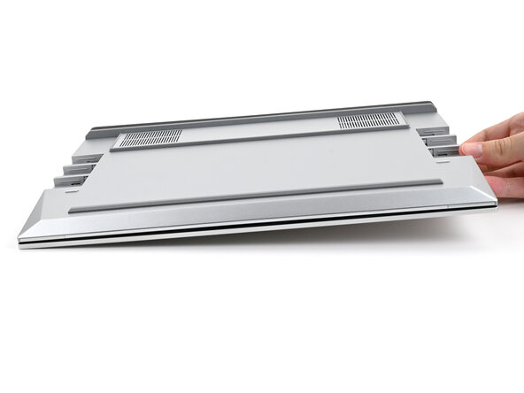
Pull the Expansion Card out of its slot and remove it.
-
Repeat for all remaining Expansion Cards.
-
-
-
Flip your laptop over and open it.
-
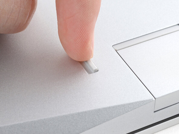
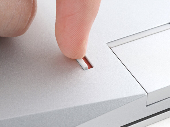
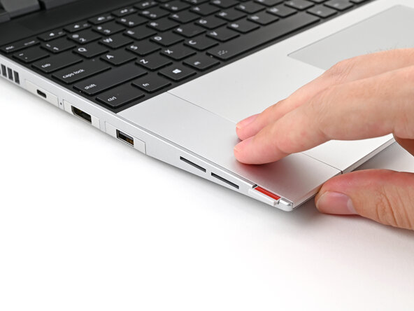
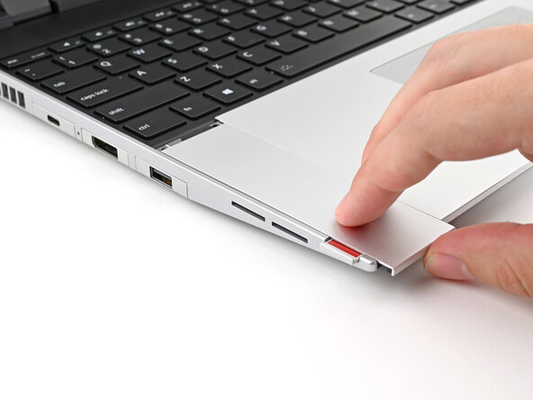
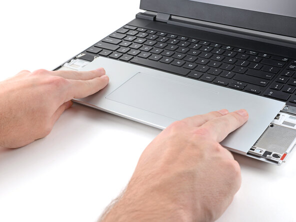
Use your fingernail to pull out the two Input Module latches and unlock them.
-
-
-
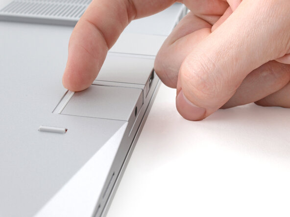
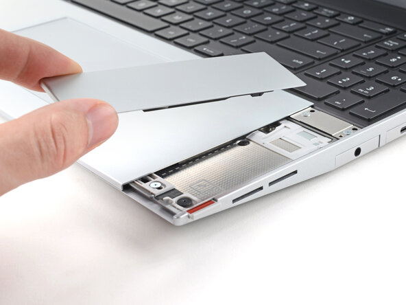
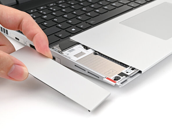
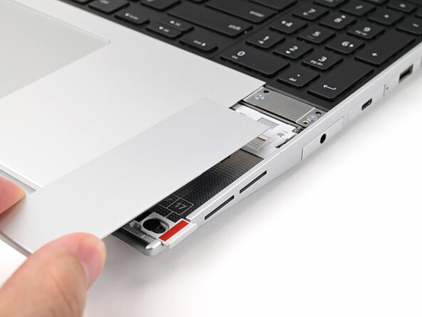
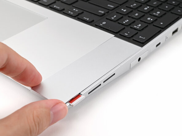
Use your fingers to slide the Touchpad Spacer toward the bottom edge of the laptop and unclip it.
-
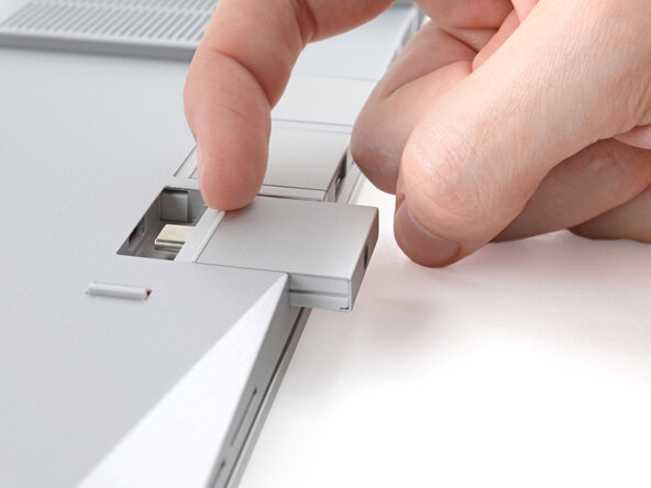
Lift the Touchpad Spacer off the laptop and remove it.
-
-
-
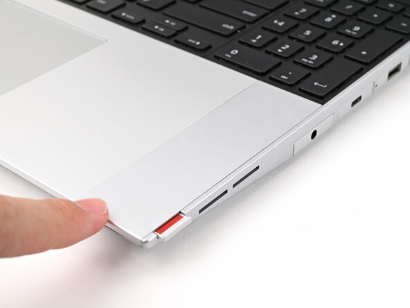
Repeat the same procedure for the other touchpad spacer.
-
-
-
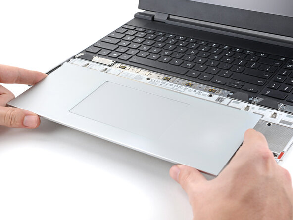
Use your fingers to slide the Touchpad Module toward the bottom edge of the laptop and disconnect it.
-
Lift the Touchpad Module and remove it.
-
-
-
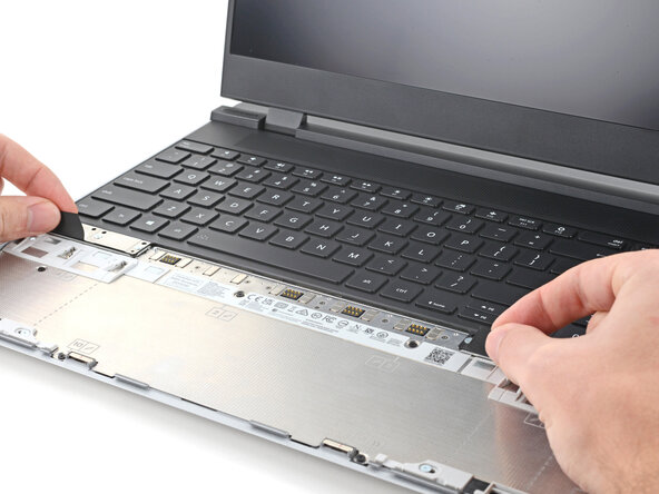
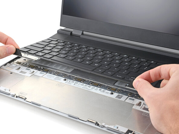
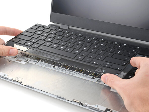
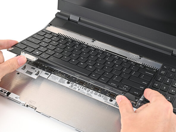
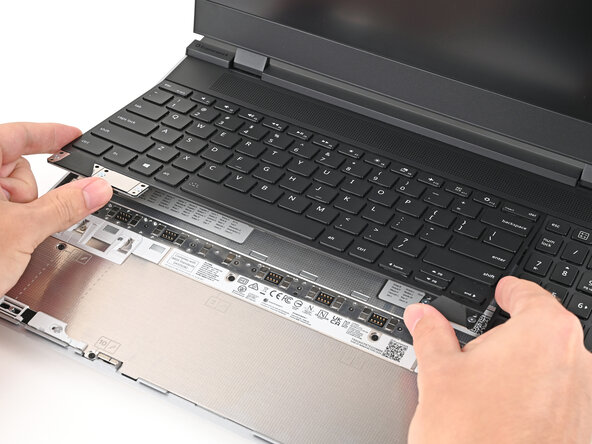
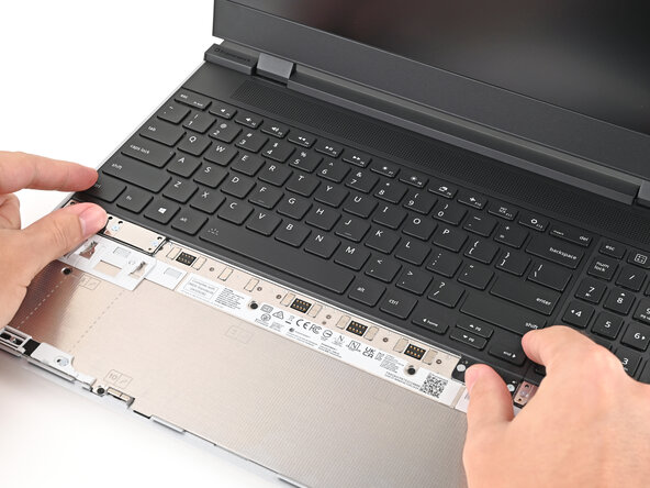
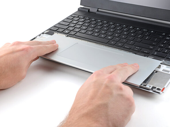
Grip the two pull tabs along the bottom of the keyboard and lift until its magnets release.
-
Remove the keyboard.
-
-
-
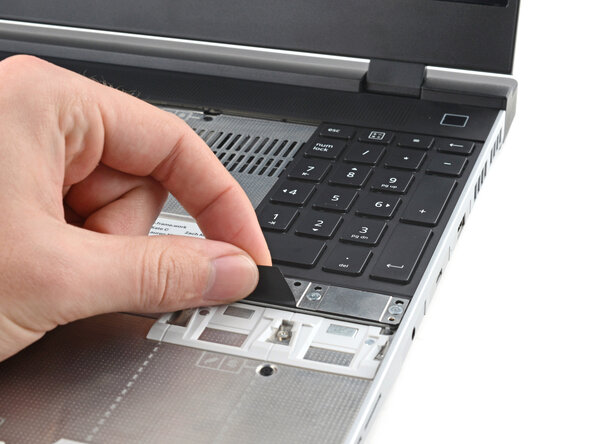
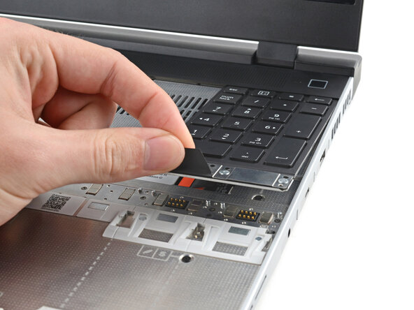
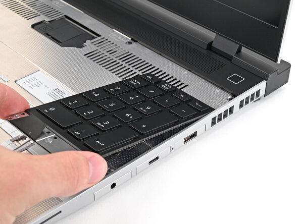
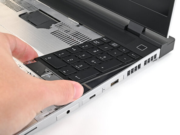
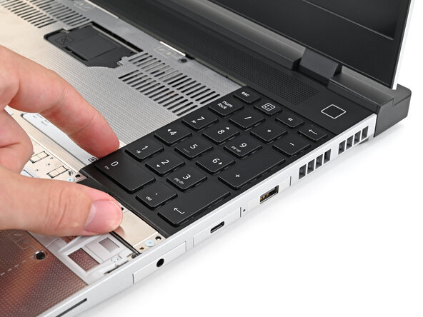
Grip the pull tab at the bottom of the Input Module and lift until its magnets release.
-
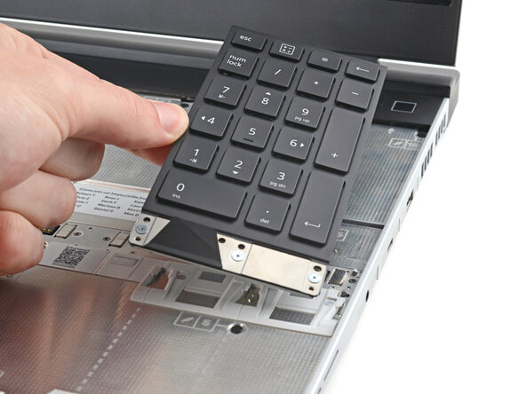
Remove the Input Module.
-
Repeat for any remaining Input Modules.
-
-
-
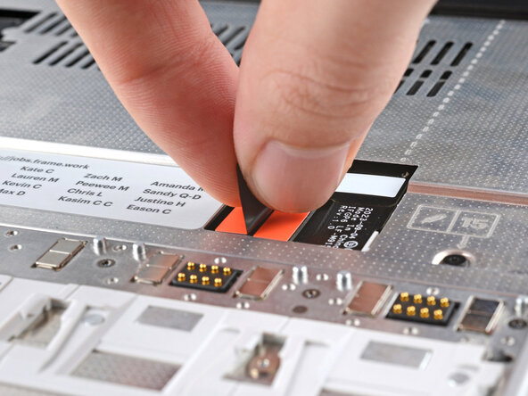
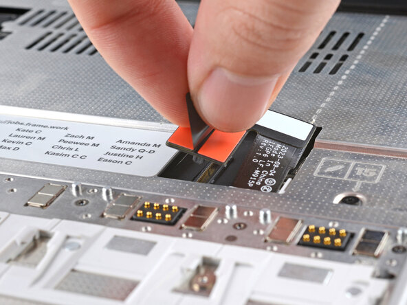
Grip the black pull tab on the midframe cable press connector.
-
Lift up to disconnect the midframe cable.
-
-
-
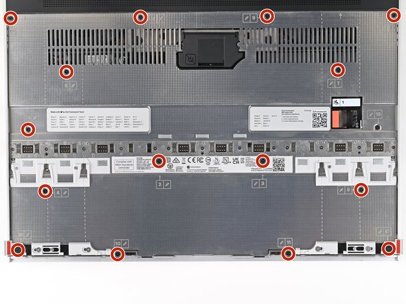
Use your Framework Screwdriver to loosen the 16 captive T5 Torx screws securing the Mid Plate.
-
-
-
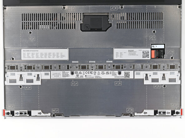
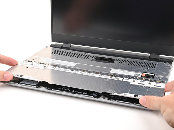
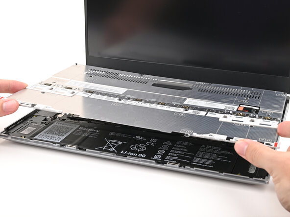
Use your fingers to lift the Mid Plate off the laptop and remove it.
-
-
-
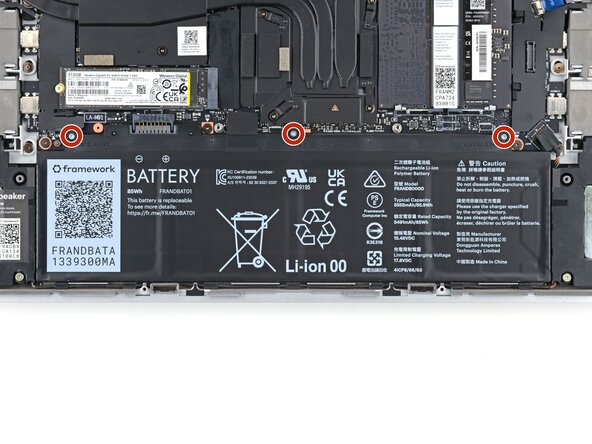
Use your Framework Screwdriver to loosen the three captive T5 Torx screws securing the battery.
-
-
-
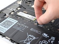
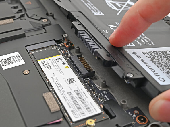
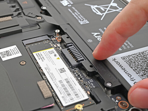
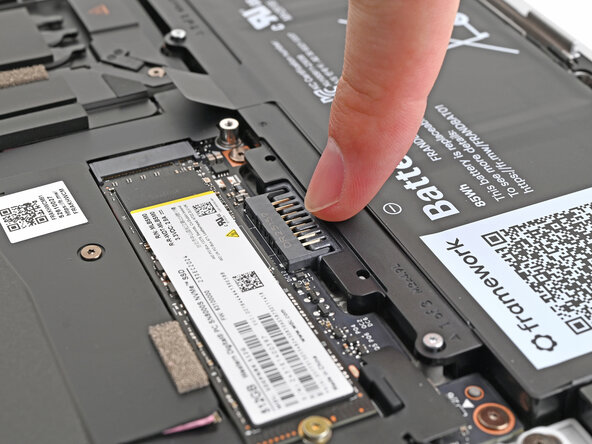
Grip the black pull tab at the top of the battery and lift to disconnect the battery connector.
-
Remove the battery.
-
-
-
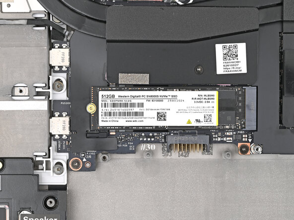
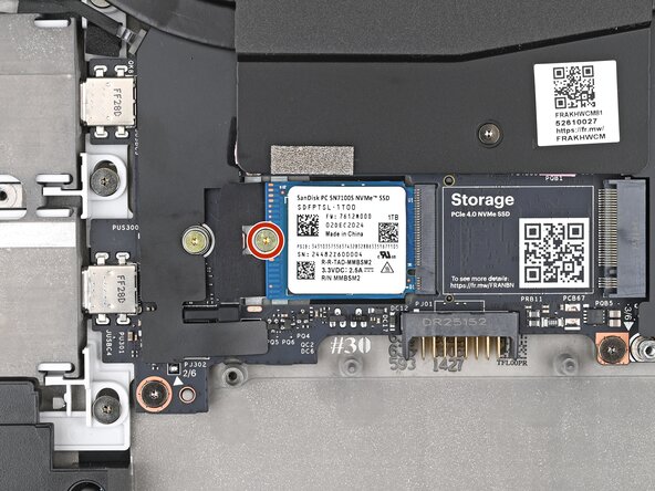
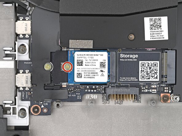
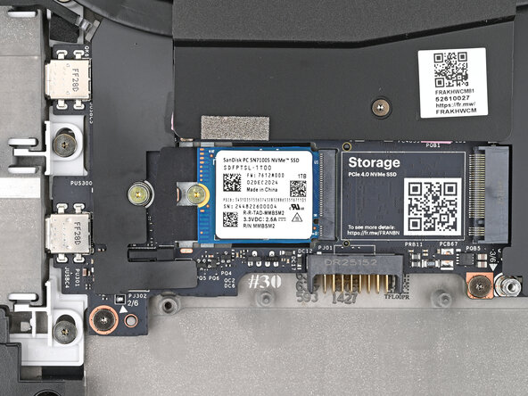
Use your Framework Screwdriver to remove the 2 mm‑long T5 Torx screw securing the SSD.
-
-
-
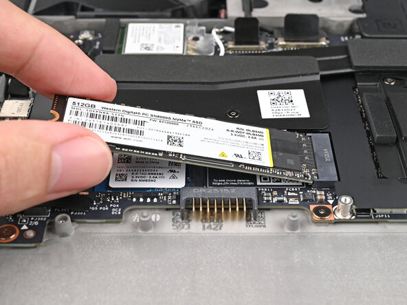
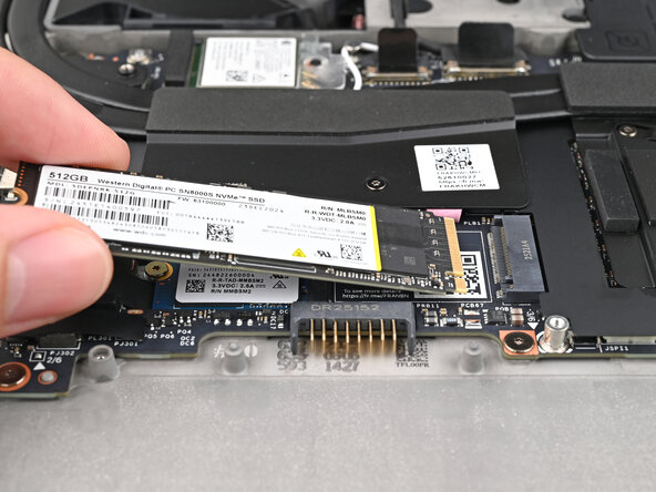
Grip the end of the SSD with the screw hole and slide it out of its socket.
-
Remove the SSD.
-
-
-
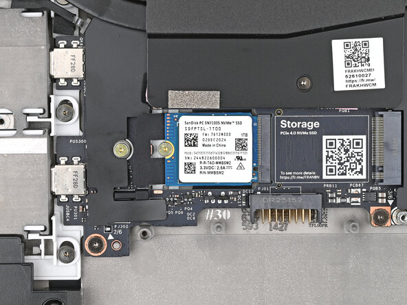
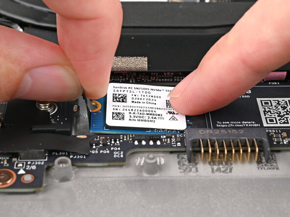
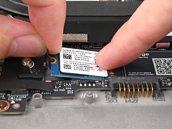
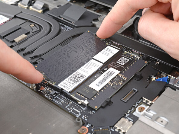
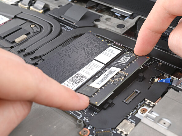
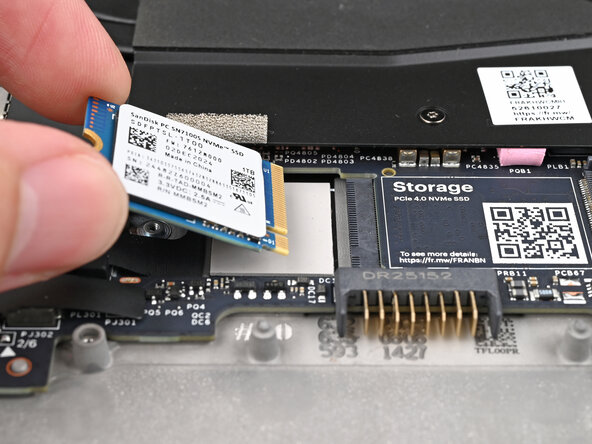
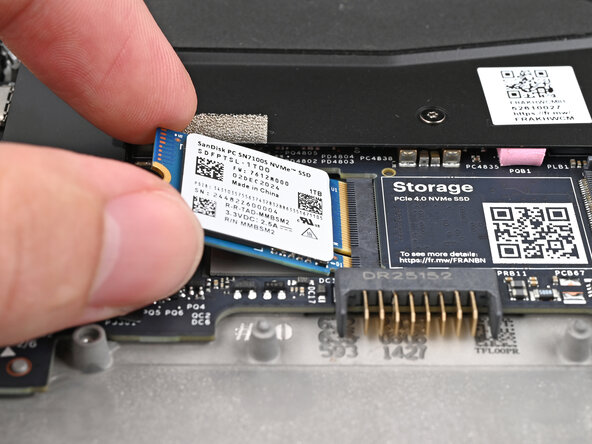
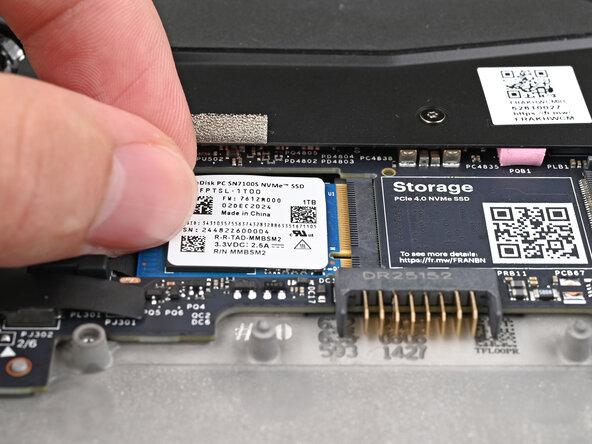
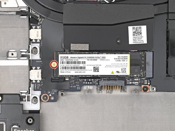
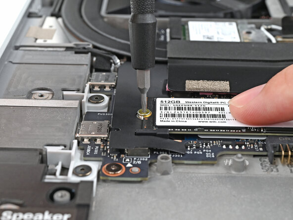
Use your Framework Screwdriver to remove the 2 mm‑long T5 Torx screw securing the secondary SSD.
-
-
-
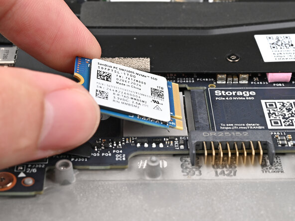
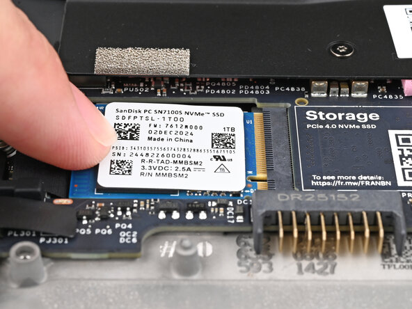
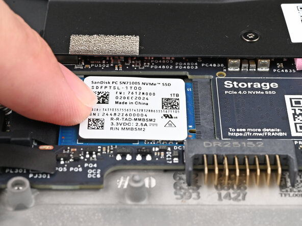
While pulling up on the black tab underneath the SSD, use your finger to slide the SSD out of its socket.
-
-
-
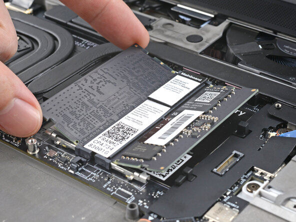
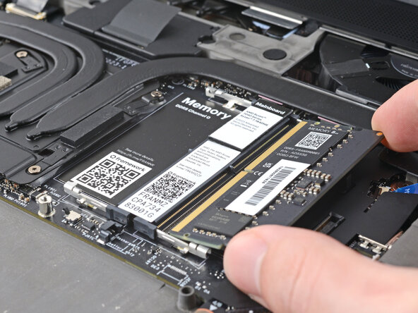
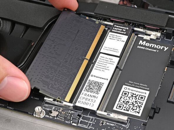
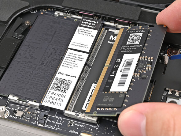
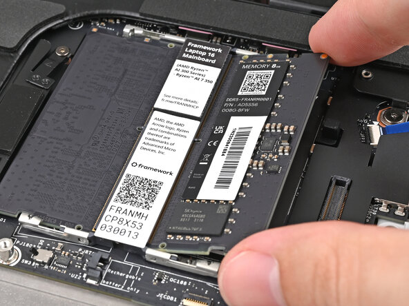
Push the two metal arms on each side of the RAM stick outward until they disengage and the stick pops up at a shallow angle.
-
Repeat for the other RAM stick.
-
-
-
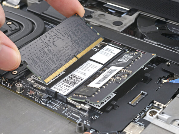
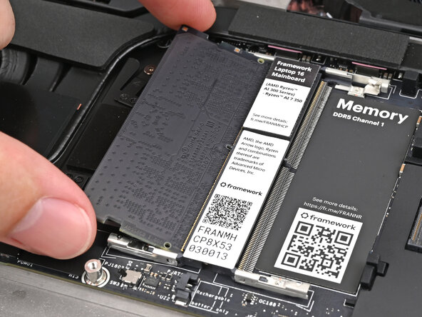
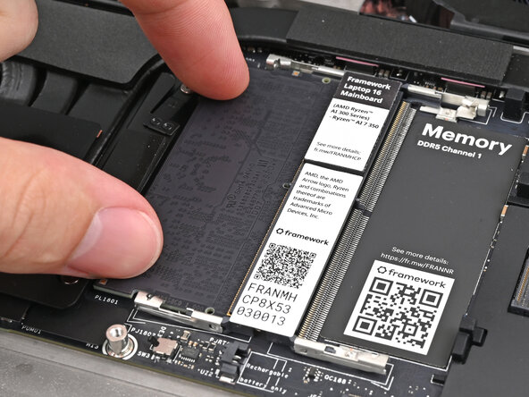
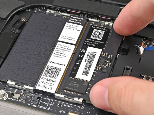
Slide the RAM stick out of its socket and remove it.
-
Repeat for the other RAM stick.
-
-
-
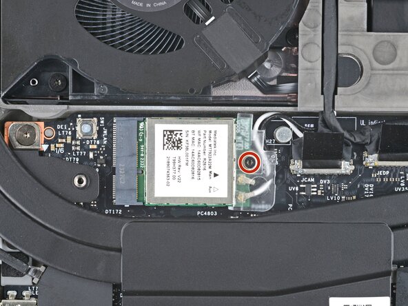
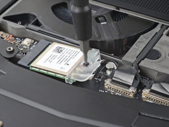
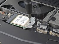
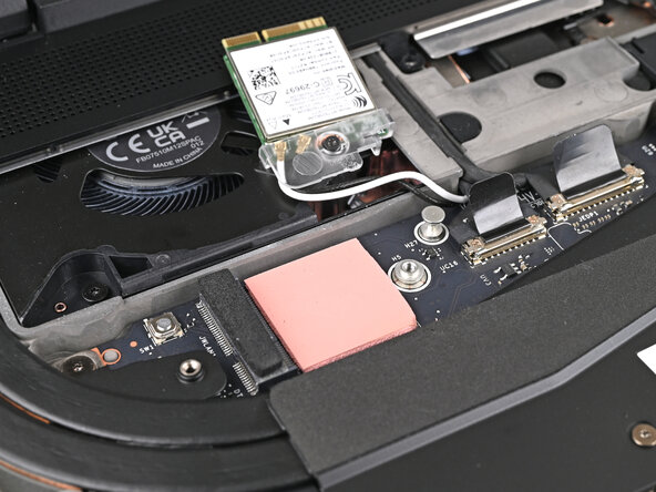
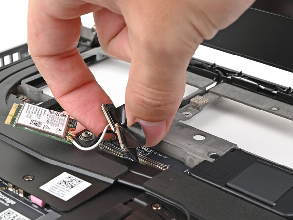
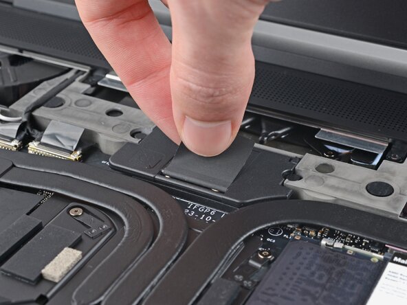
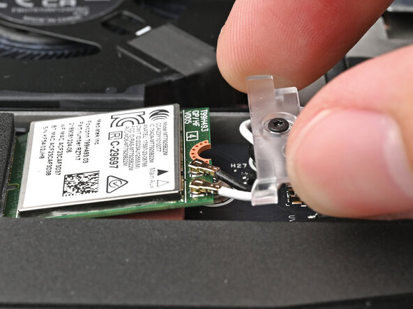
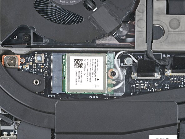
Use your Framework Screwdriver to loosen the captive T5 Torx screw securing Wi-Fi module.
-
-
-
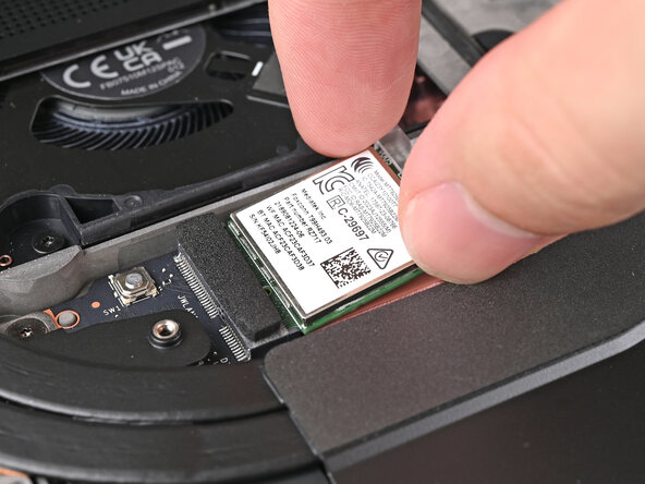
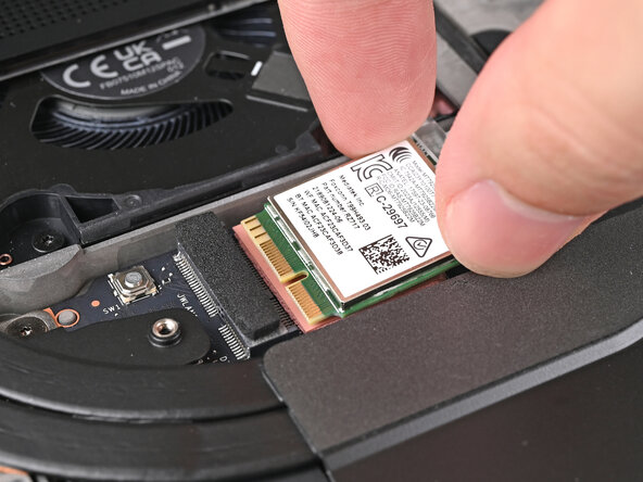
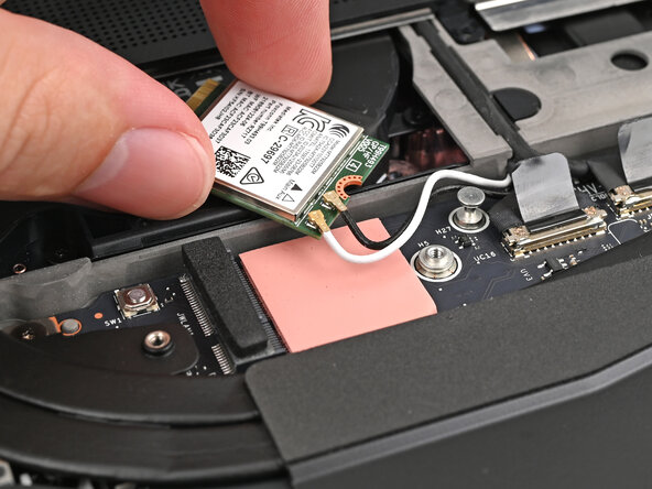
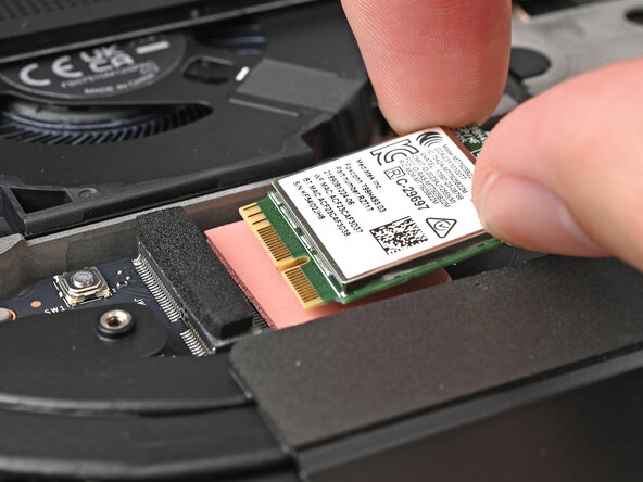
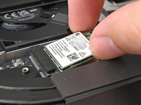
Grip the end of the Wi-Fi module with the screw hole and slide it out of its socket.
-
-
-
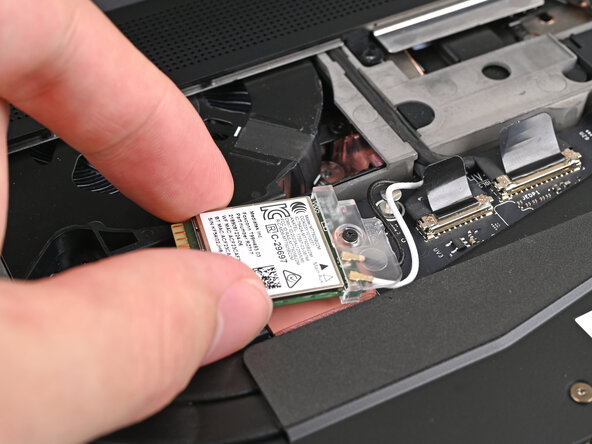
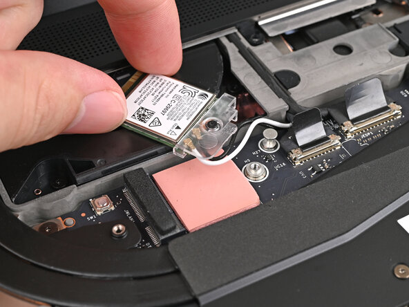
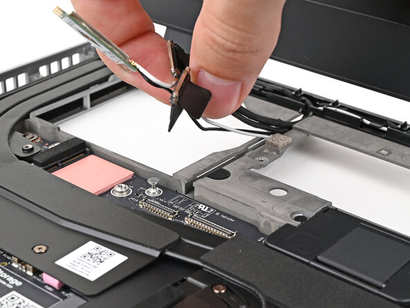
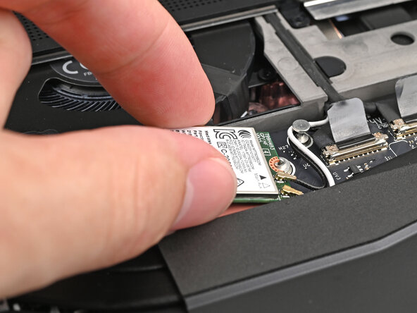
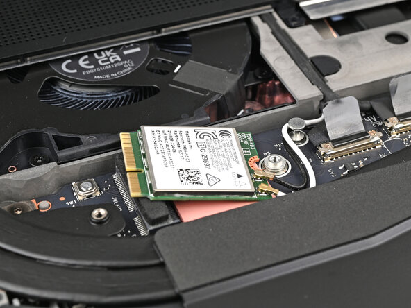
Rotate the Wi-Fi module towards the top of the laptop to keep it out of the way of the Mainboard.
-
-
-
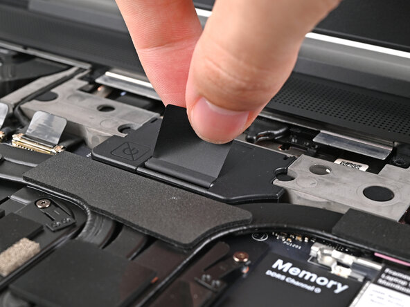
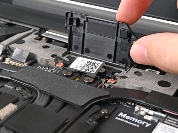
Lift the interposer door by its black pull tab and let it rest upright.
-
-
-
If you have the Graphics Module, use your Framework Screwdriver to loosen the four captive T5 Torx screws securing the interposer.
-
If you have the Expansion Bay Shell, use your Framework Screwdriver to loosen the three captive T5 Torx screws securing the interposer.
-
-
-
-
Lift the interposer by its pull tab and remove it.
-
-
-
Use your Framework Screwdriver to loosen the two captive T5 Torx screws securing the module in the Expansion Bay.
-
Close the interposer door before continuing.
-
-
-
Close your laptop and flip it over.
-
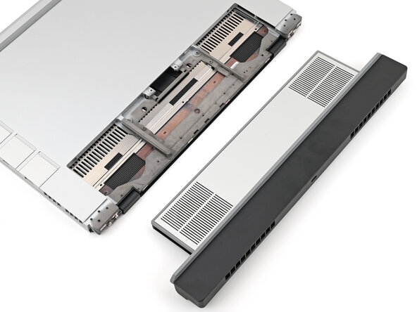
Slide the Expansion Bay Module out of the laptop and remove it.
-
Reopen your laptop and flip it over.
-
-
-
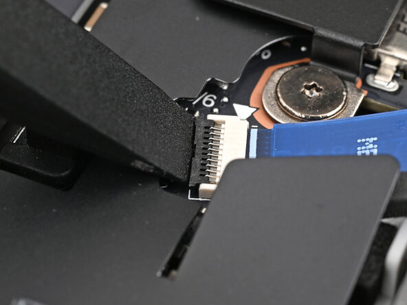
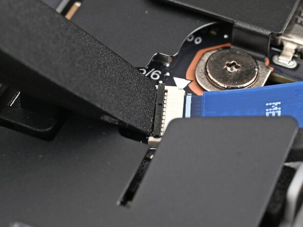
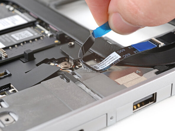
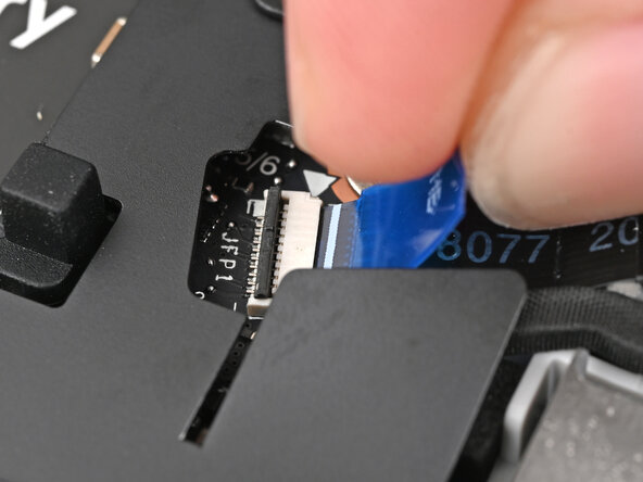
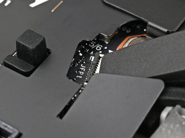
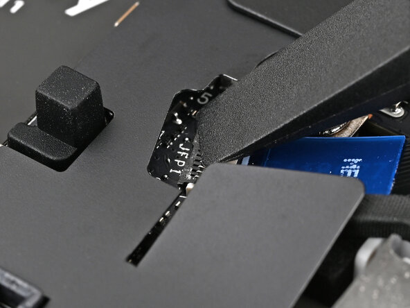
Use the flat end of your Framework Screwdriver, or a clean fingernail, to lift up the locking tab on the fingerprint sensor ZIF connector next to the memory.
-
-
-
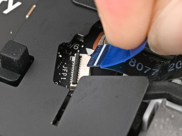
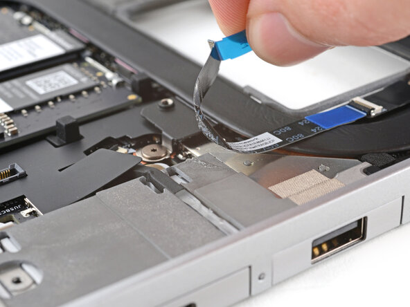
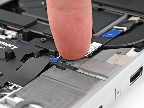
Use your fingers, to grip the blue pull tab and slide the fingerprint sensor cable straight out of its socket.
-
-
-
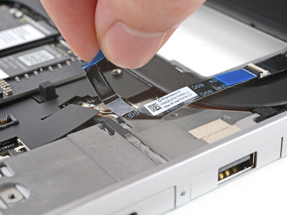
Use your fingers to peel the fingerprint sensor cable away from the frame and separate the adhesive.
-
-
-
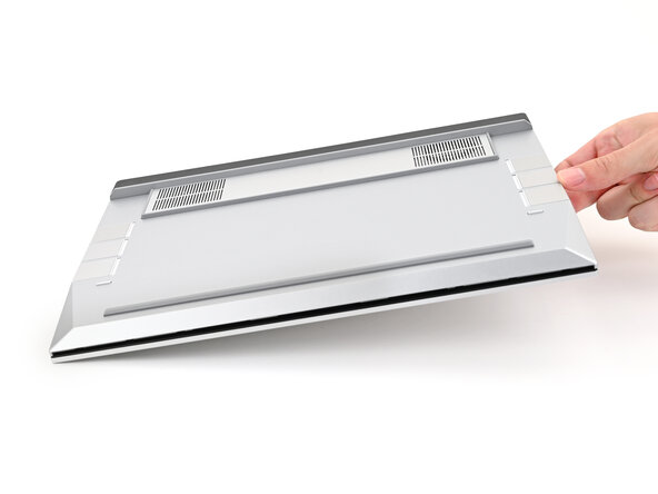
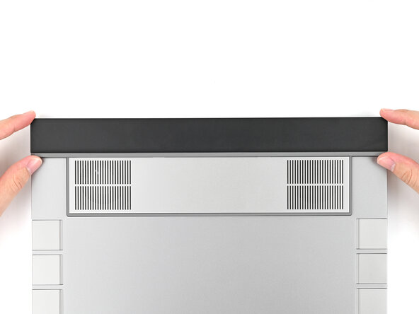
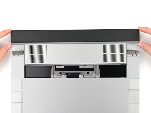
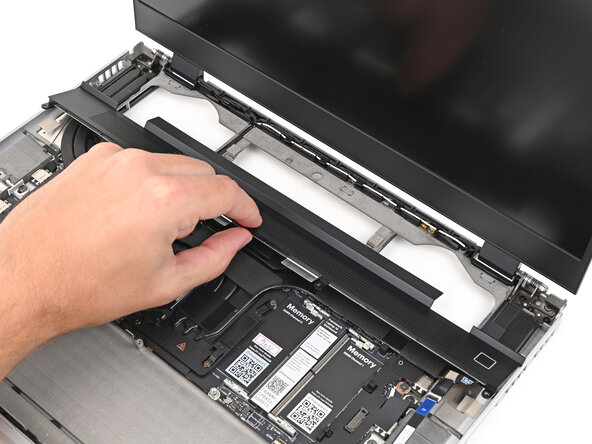
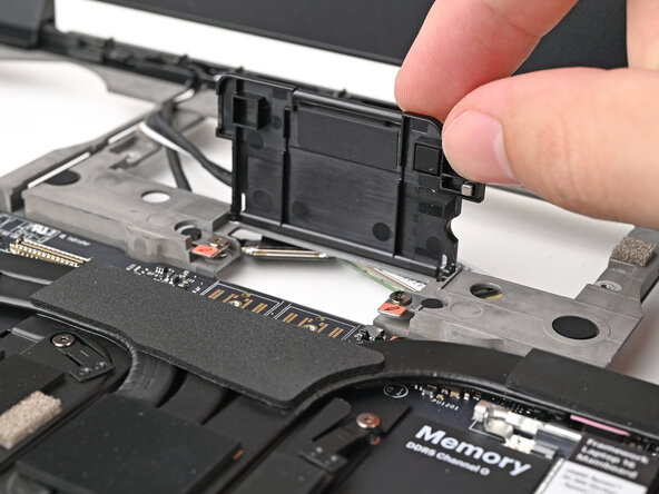
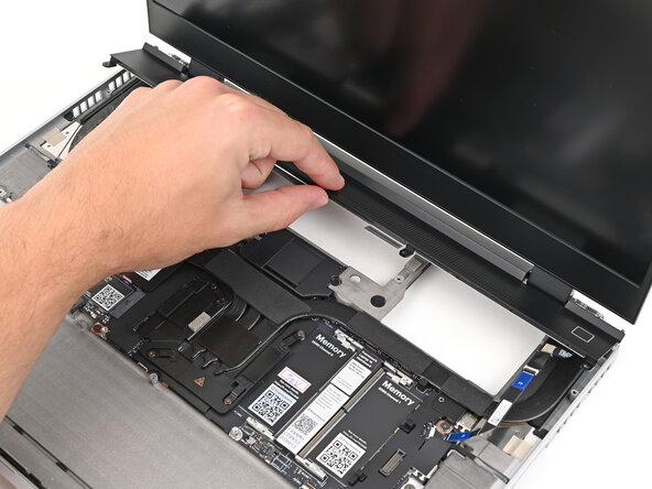
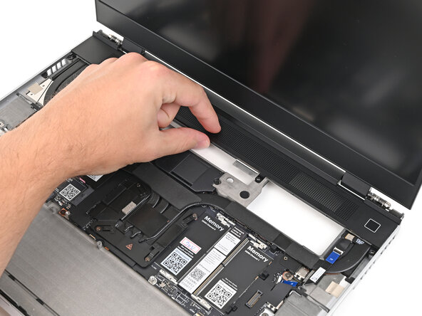
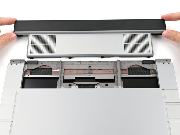
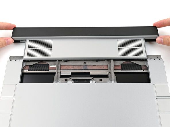
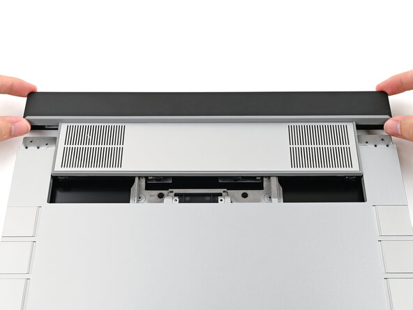
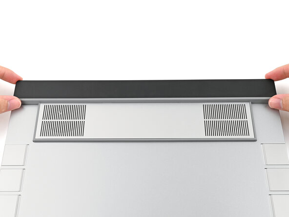
Lift the bottom of the ventilation plate and pull it away from the laptop until the magnets release.
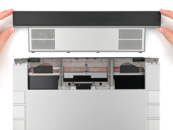
-
Remove the ventilation plate.
-
-
-
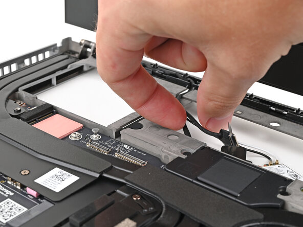
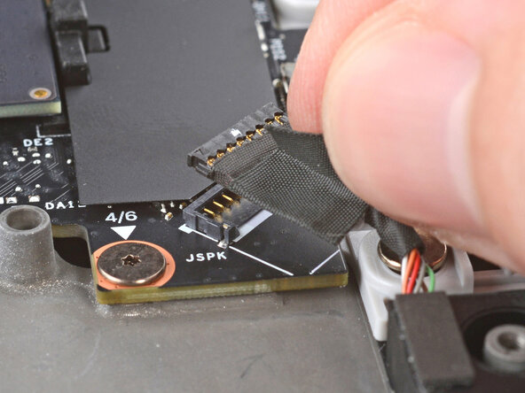
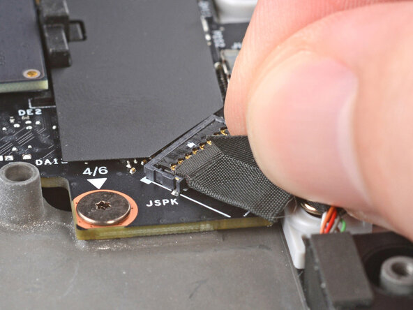
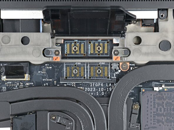
Lift the speaker cable connector by its black pull tab and disconnect it.
-
-
-
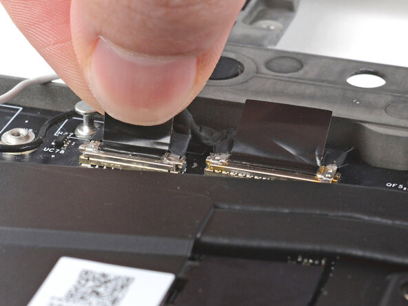
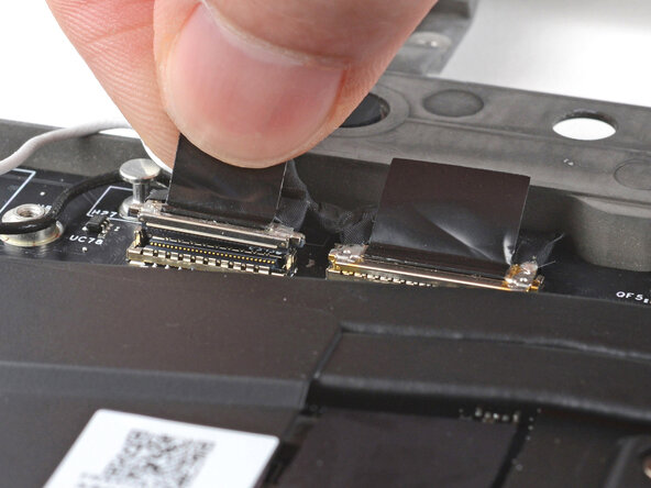
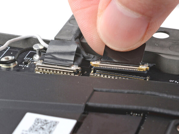
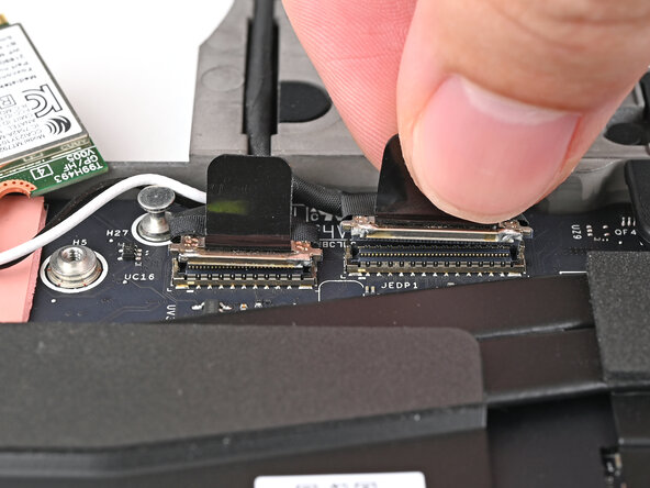
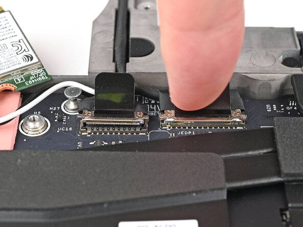
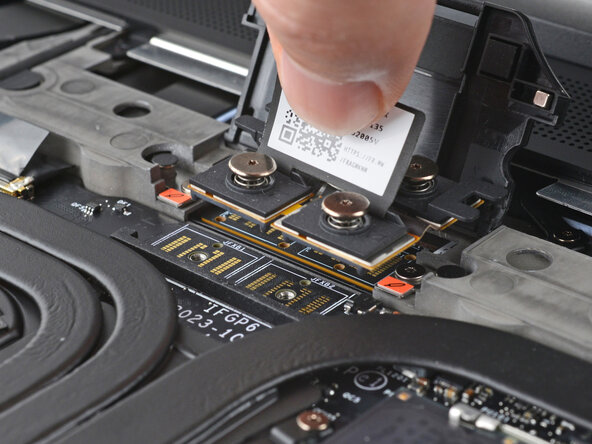
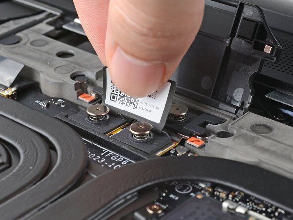
Grip the webcam cable connector to the right of the Wi-Fi module slot by its pull tab and lift up to disconnect it.
-
Repeat for the display cable connector next to it.
-
-
-
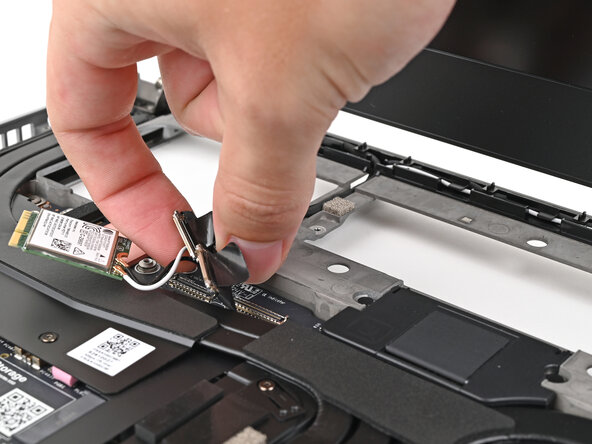
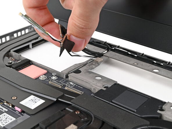
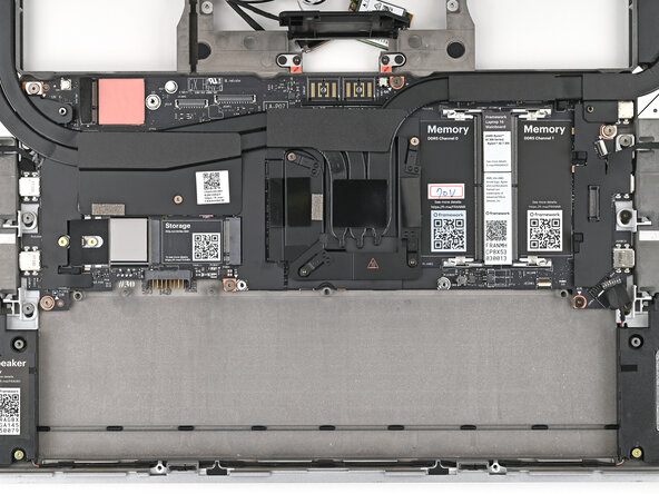
Lift the display, webcam, and Wi-Fi module cables out of their slot in the frame enough to give room for the Mainboard to lift straight up.
-
-
-
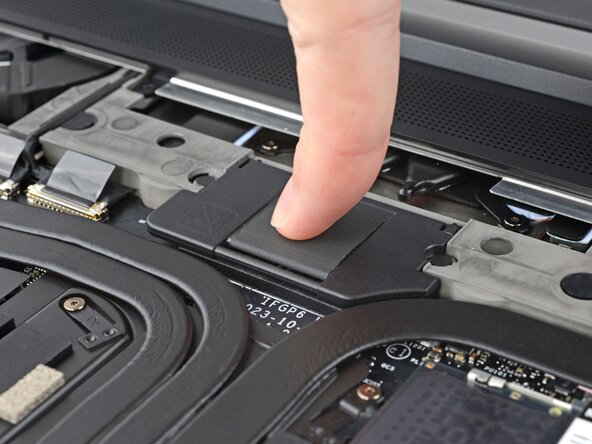
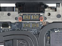
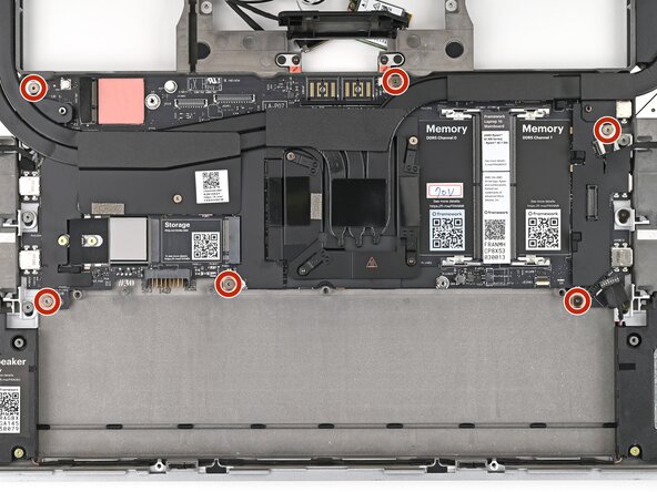
Lift up the interposer door to reveal the screw underneath.
-
Use your Framework Screwdriver to remove the six 2 mm‑long T5 Torx screws securing the Mainboard.
-
-
-
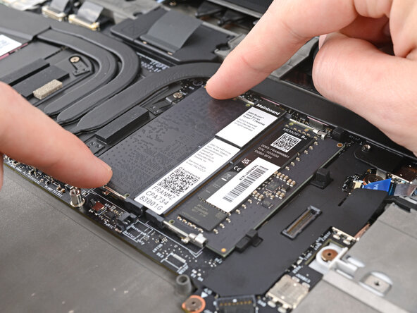
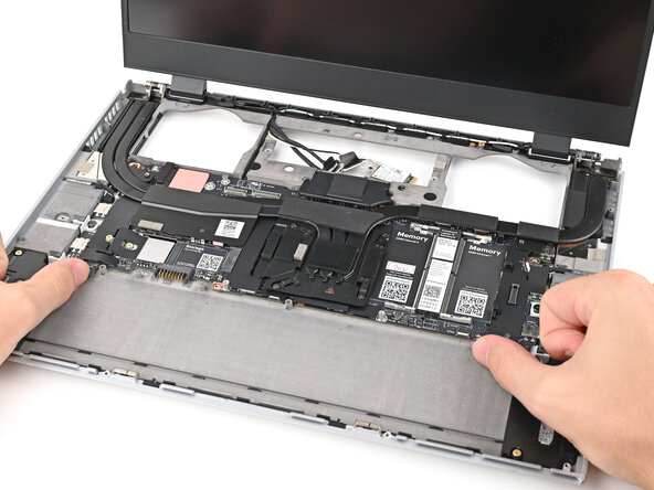
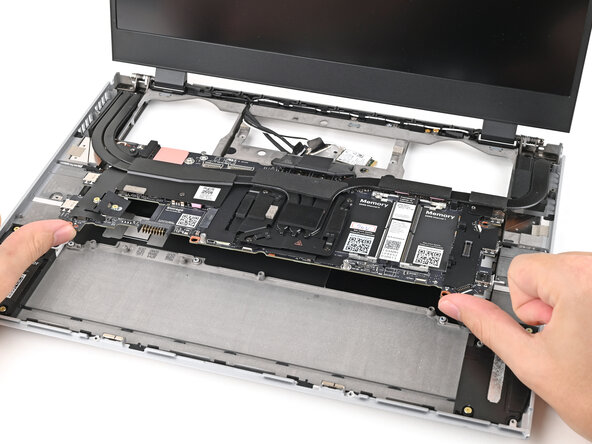
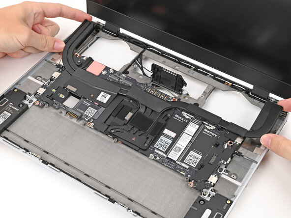
Use your fingers to lift the bottom edge of the Mainboard enough to grip its edges.
-
Lift the Mainboard off its alignment pegs and remove it.
-
-
-
Congratulations on completing disassembly! The remaining steps will show how to reassemble your Framework Laptop.
-
-
-
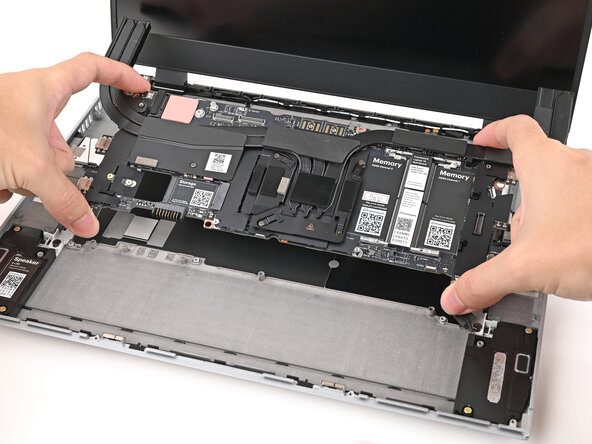
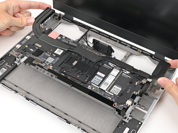
Grab the Mainboard by the curving pipes of its heatsink.
-
Place the Mainboard into the laptop and onto its alignment pegs.
-
-
-
Use your Framework Screwdriver to install the six 2 mm‑long T5 Torx screws securing the Mainboard.
-
-
-
Route the display, webcam, and Wi-Fi module cables into their slots in the frame.
-
-
-
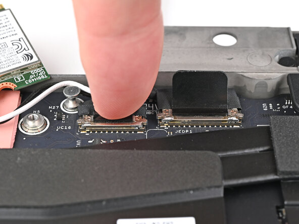
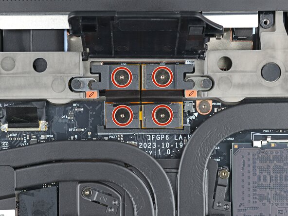
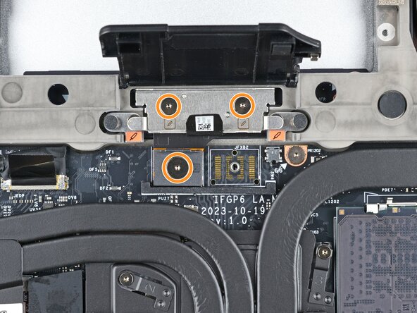
Press the two display connectors straight down into their sockets to connect them.
-
-
-
Press the speaker cable connector straight down into its socket to connect it.
-
-
-
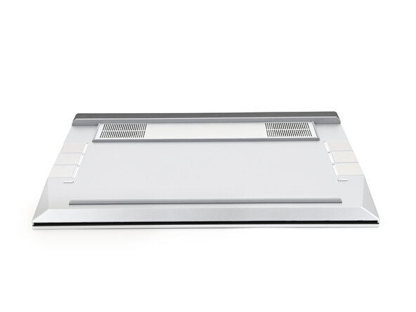
Lay the ventilation plate along the top edge of the laptop and let its magnets pull into place.
-
-
-
Use your fingers, to grip the blue pull tab and slide the fingerprint sensor cable straight into its socket.
-
-
-
Use the flat end of your Framework Screwdriver, or a clean fingernail, to press down the locking tab on the fingerprint sensor ZIF connector.
-
-
-
Press the fingerprint sensor cable to the frame to re-adhere it.
-
-
-
Close your laptop and flip it over.
-
Align the Expansion Bay Module with its slot in the laptop.
-
-
-
While keeping the module level with the laptop, slide it into its slot.
-
Reopen your laptop and flip it over.
-
-
-
Use your Framework Screwdriver to tighten the two captive T5 Torx screws securing the Expansion Bay Module.
-
-
-
Place the interposer over its spot between the Mainboard and the module.
-
-
-
If you have the Graphics Module, use your Framework Screwdriver to tighten the four captive T5 Torx screws securing the interposer.
-
If you have the Expansion Bay Shell, use your Framework Screwdriver to tighten the three captive T5 Torx screws securing the interposer.
-
Close the interposer door.
-
-
-
Rotate the Wi-Fi Module back into place, making sure the antenna cables wrap around their silver peg on the Mainboard and tuck underneath the heat sink.
-
-
-
Align the Wi-Fi module's gold contacts and notch with the socket on the Mainboard.
-
Insert the Wi-Fi module into the socket at a shallow angle. The gold contacts should mostly be covered by the socket.
-
-
-
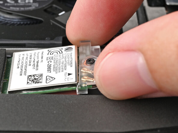
Slide the clear Wi-Fi module cover on the module and align its screw with the screw hole cutout.
-
-
-
Use your Framework Screwdriver to tighten the captive T5 Torx screw securing Wi-Fi module.
-
-
-
Orient the module with its label facing down and align the gold contacts with the left socket labeled DDR5 Channel 0.
-
Insert the contact edge into the socket at a shallow angle. The gold contacts should mostly be covered by the socket.
-
Press the edges of the memory module down until the side clips lock it in place.
-
-
-
Repeat the previous step for the other socket labeled DDR5 Channel 1, except orient the module so its label is facing upward.
-
-
-
Align the SSD's gold contacts with its socket.
-
Insert the SSD partially into the socket at a shallow angle. You should still be able to see most of the gold contacts.
-
Press the SSD flat to the Mainboard.
-
-
-
While keeping the SSD flat to the Mainboard, push it into its socket until its golden contacts are completely covered.
-
-
-
Use your Framework Screwdriver to install the 2 mm‑long T5 Torx screw securing the SSD.
-
-
-
Insert the SSD into the socket at a shallow angle. The gold contacts should mostly be covered by the socket.
-
-
-
While holding the SSD flat to the Mainboard, use your Framework Screwdriver to install the 2 mm‑long T5 Torx screw securing the SSD.
-
-
-
Align the battery connector over its socket and lay the battery into its well.
-
Lightly press the battery down to connect it.
-
-
-
Use your Framework Screwdriver to tighten the three captive T5 Torx screws securing the battery.
-
-
-
Place the Mid Plate on the laptop, making sure it sits evenly on its alignment pegs.
-
-
-
Use your Framework Screwdriver to tighten the 16 captive T5 Torx screws in order (starting with 2) to secure the Mid Plate evenly.
-
-
-
Align the Mid Plate cable press connector over its socket and press down to connect it.
-
-
-
Align the top edge of the Input Module with the top edge of the laptop.
-
Lay the Input Module on the laptop and let the magnets pull the keyboard into place
-
Repeat for any remaining Input Modules.
-
-
-
Align the top edge of the keyboard with the top edge of the laptop.
-
Lay the keyboard on the laptop and let the magnets pull the keyboard into place
-
-
-
Place the Touchpad Module flat on its cutout so its clips are properly aligned.
-
Press the Touchpad Module down and slide it into place so it lines up evenly with the bottom edge of the laptop.
-
-
-
Place the Touchpad Spacer over its spot on the laptop with the bottom edge overhanging slightly.
-
Slide the Touchpad Spacer towards the top of the laptop to secure it.
-
Repeat the same procedure for the other Touchpad Spacer.
-
-
-
Push the Input Module latches back into place to lock them.
-
-
-
Close the laptop and flip it over.
-
-
-
Slide an Expansion Card into an Expansion Card slot.
-
Repeat for all remaining Expansion Cards.
-
-
-
Use your finger to flip both latches and lock the row of Expansion Cards above them.
-
-
-
If you're installing a new Graphics Module, check out this page to install the associated driver bundle.
-


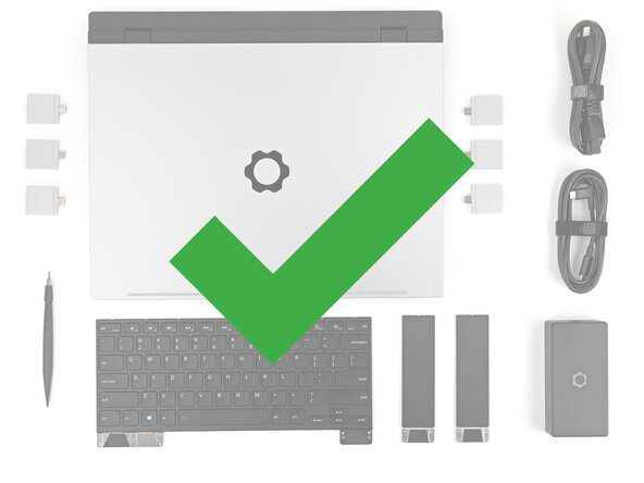


You finished fixing your Framework Laptop!
Take your e-waste to an R2 or e-Stewards certified recycler.
If you need help, contact Framework support.
You finished fixing your Framework Laptop!
Take your e-waste to an R2 or e-Stewards certified recycler.
If you need help, contact Framework support.
