crwdns2915892:0crwdne2915892:0
This guide will be helpful if you need to replace any part of the camera that does not have a specific repair guide. To complete this guide, you will need to desolder wires from the motherboard and circuit boards. Learn more about soldering here.
crwdns2942213:0crwdne2942213:0
-
-
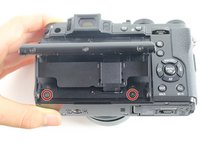
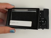
Turn the camera upside down.
-
Place your thumb on the switch, and slide it towards the center of the camera.
-
-
-
Once you have the battery compartment open, slide the orange tab away from the battery until it ejects.
-
-
-
Begin by removing the outside screws using a Phillips #000 Screwdriver:
-
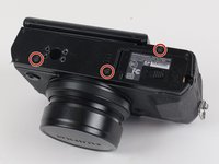
Remove the three 3.6 mm silver screws located on the bottom of the camera.
-
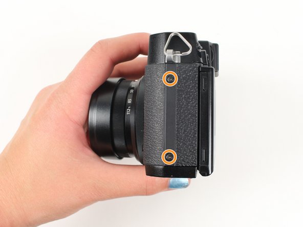
Remove all four of the 4.7 mm screws from the sides of the camera.
-
-
-
Remove all screws below using a Phillips #000 Screwdriver:
-
Lift up the screen and remove the two 4.5 mm screws located in the bottom corners.
-
Remove the 4.0 mm screw that is located behind the screen and directly under the eye piece.
-
-
-
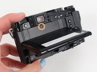
Carefully lift up the bottom piece of the camera to remove it.
-
-
-
Gently pull off the back of the camera from the left side so that it is partially open.
-
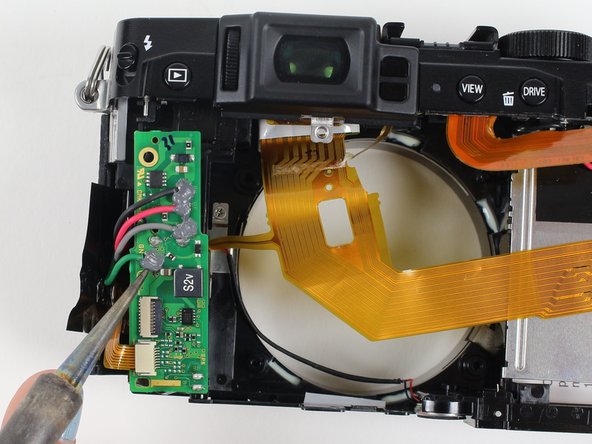
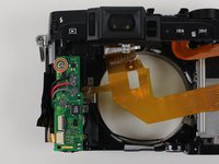
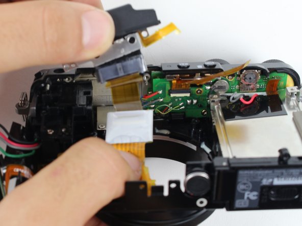
Use a spudger to lift up the tab holding the orange strip and slide the strip out to disconnect it
-
-
-
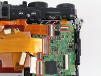
-
For all five indicated orange strips:
-
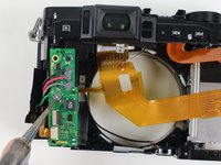
Use a spudger to lift up the tab holding the orange strip and slide the strip out to disconnect it.
-
-
-
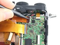
For the last orange strip located behind the top strip:
-
Use a spudger to lift up the tab holding the orange strip and slide the strip out to disconnect it.
-
-
-
For the two orange strips attached to the capacitor circuitboard:
-
Use a spudger to lift up the tab holding the orange strip and slide the strip out to disconnect it.
-
-
-
Remove all screws listed below using a Phillips #000 screwdriver:
-
Remove the two 3.4 mm screws at the bottom of the silver plate.
-
Hold back the clear strip to reveal a 2.8 mm screw on the left of the silver plate and remove it.
-
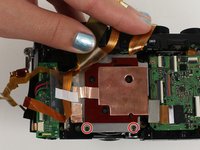
Peel back the copper plate.
-
-
-
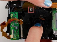
Remove the three 2.6 mm screws located in the top two corners and the bottom right corner of the motherboard using a Phillips #000 screwdriver.
-
-
-
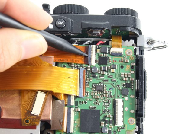
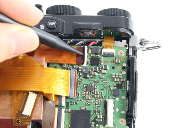
Tilt up the motherboard to locate the black, grey, and red wires.
-
Desolder these wires in order to completely remove the motherboard.
If you want to remove baterry holder case you'll have to unscrew it from the body through the hole you see on the plate. There's another hole under the black tape. Use it to reach another screw. You can then get the case out and work easily for soldering.
-
-
-
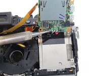
Remove the four 4.4 mm silver screws at the corners of the lens using a Phillips #000 screwdriver.
-
-
-
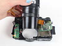
Pull the lens toward the bottom of the camera so it can clear the silver tab.
-
Then push the lens with your index fingers from the front of the camera until it is removed.
-
-
-
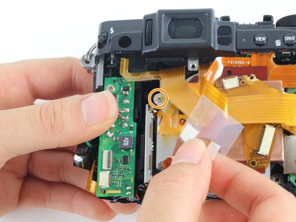
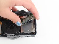
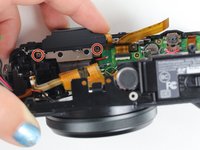
Remove the silver 3.4 mm screw from the top left corner of the capacitor circuitboard using a Phillips #000 screwdriver.
-
Desolder the red, black, grey, and green wires attached to the capacitor circuitboard so the circuitboard is disconnected and can be set aside.
-
-
-
Rotate the camera so you are looking at the bottom.
-
Remove the two silver 3.4 mm screws on the silver plate that are holding the eyepiece using a Phillips #000 screwdriver.
-
Lift the eyepiece out of the camera.
-
-
-
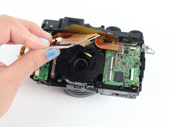
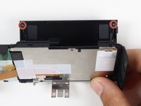
Remove the two black 3.7 mm screws in the back corners of the screen plate using a Phillips #000 screwdriver.
-
Lay the back panel flat to lift off the clear casing that is over the LCD screen.
-
-
-
You have disassembled the Fujifilm X30 camera!
-


To reassemble your device, follow these instructions in reverse order.
To reassemble your device, follow these instructions in reverse order.
crwdns2935221:0crwdne2935221:0
crwdns2935229:09crwdne2935229:0

crwdns2915084:0crwdne2915084:0

Cal Poly, Team 70-3, Forte Winter 2016 crwdns2935289:0Cal Poly, Team 70-3, Forte Winter 2016crwdne2935289:0
CPSU-FORTE-W16S70G3
crwdns2931471:05crwdne2931471:0
crwdns2935297:04crwdne2935297:0
crwdns2947412:02crwdne2947412:0
the big question is how to repair the common stuck open flash?
and the broken battery latch (orange tab)? Thanks.