
Dell XPS 13 9365 2-in-1 Display Assembly Replacement

crwdns2944107:0crwdnd2944107:0Melissa Schleincrwdnd2944107:0crwdnd2944107:0crwdnd2944107:02crwdnd2944107:0crwdne2944107:0
crwdns2944111:0Mud 7, 2024crwdne2944111:0
crwdns2915892:0crwdne2915892:0
crwdns2942287:0crwdne2942287:0Use this guide to remove or replace this display assembly (screen) on your Dell XPS 13 9365 2-in-1 laptop. The display assembly on this laptop refers to the entire upper portion of the laptop, which houses the screen display.
crwdns2942213:0crwdne2942213:0
crwdns2943215:0crwdne2943215:0


crwdns2944105:0crwdne2944105:0
-
-
Use a Torx T4 screwdriver to remove the eight screws (M2x3) that secure the base cover to the palm-rest assembly.
-
-
-
Use your fingertips to lift the system badge open and reveal the single case screw.
-
Use a Phillips #000 screwdriver to remove the screw (M1.6x4) that secures the base cover to the palm-rest assembly.
-
-
-
Starting from the front corner of the computer, pry up the base cover using a spudger and lift the base cover off the palm-rest assembly.
-
-
-
Disconnect the battery cable from the system board.
-
-
-
Use a Phillips #000 screwdriver to remove the two screws (M1.6x4) that secure the battery to the palm-rest assembly.
-
-
-
Use a Phillips #000 screwdriver to remove the six screws (M2x3) that secure the battery to the palm-rest assembly.
-
-
-
Lift the battery off the palm-rest assembly.
-
-
-
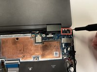
Use a Phillips #000 screwdriver to remove the screw (M1.6x2.5) that secures the wireless-card bracket to the motherboard.
-
-
-
Lift the wireless-card bracket off the wireless card.
-
-
crwdns2935267:0crwdne2935267:0Tweezers$4.99
-
Use a pair of nylon tipped tweezers to gently disconnect the antenna cables from the wireless card.
-
-
-
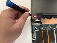
Peel off the tape that secures the display cable to the M.2 solid-state drive heatsink.
-
-
-
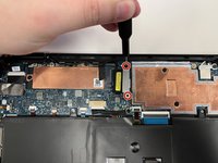
Use a Phillips #000 screwdriver to remove the two screws (M1.6x2.5) that secure the display cable bracket to the motherboard.
-
Lift the display cable bracket off the display cable.
-
-
-
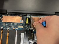
Use the pull tab to disconnect the display cable from the motherboard.
-
-
-
Disconnect the touch-screen cable from the system board (labeled "TS").
-
-
-
Disconnect the camera cable from the system board.
-
-
-
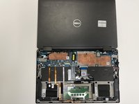
Open the palm-rest assembly fully and place the display assembly and palm-rest assembly face down.
-
Use a Phillips #000 screwdriver to remove the six screws (M2.5x3.5) that secure the display hinges to the palm-rest assembly. There are three on each side.
-
-
-
Lift the display assembly off the palm-rest assembly.
-


To reassemble your device, follow these instructions in reverse order.
To reassemble your device, follow these instructions in reverse order.
crwdns2935221:0crwdne2935221:0
crwdns2935227:0crwdne2935227:0

crwdns2915084:0crwdne2915084:0

University of Alabama, Team 3-4, Bedsole Spring 2022 crwdns2935289:0University of Alabama, Team 3-4, Bedsole Spring 2022crwdne2935289:0
UA-BEDSOLE-S22S3G4
crwdns2931471:03crwdne2931471:0
crwdns2935297:03crwdne2935297:0
crwdns2947410:01crwdne2947410:0
how to disassembly hinge for replace the video cable?
Keeps track of the screws is vital. Put screws together put in seperate piles for each level. You want to be able to put the same screw back in the same place, and the screws are small so easy to mess up.
Alexander Wolf - crwdns2934203:0crwdne2934203:0