crwdns2933423:0crwdne2933423:0

Released in March 2017, the G6 is LG's flagship phone running Android 7.0. This device is available across all major wireless carriers. Physical repair of this device may eliminate water resistance and cause the device to be vulnerable to water damage.

crwdns2934591:056crwdne2934591:0 crwdns2934593:0crwdne2934593:0

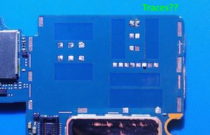
SIM / SD Reader solder pads torn off board

Hello fixers,

I screwed up - can anyone help?

I attempted to replace the sim/sd reader on this phone. (The reader had been damaged by a broken sim tray; a piece of the tray was completely stuck in the back of the reader, and one of the contacts for the sim had snapped off).

I set to work removing the broken reader: flux on, taped surrounding area, and heated up with a rework hot air gun. The solder seemed reluctant to let go, and I was worried I was overheating other components. I pulled too hard on the reader and ripped a bunch of pads off the board. (It’s amazing what you can achieve with a lot of inexperience).

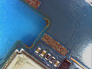
Please see pictures. There is a total of 10 pads pulled out, plus one which has half lifted.

There is nothing else wrong with this phone, and I would like to fix it if at all possible; however it's not worth spending much money on, so I don't really want to send it away - I would rather have a go at it myself. I know its beyond my current skill level to guarantee a good result, but I would like to have a shot at it just for the sake of learning, and if it works, it’ll be a bonus and I'll be a very happy chap!

  • Can this be repaired, or is it impossible?
  • Where and how do these pads connect - i can't see any traces?
  • Do I need a schematic for this board? ( I have tried scouring cyberspace without any luck, but maybe looking in the wrong places).
  • Do the 8 pads round the edge of the Reader need a different approach to the 2/3 pads which are for the microSD contacts?

Any advice, comments, etc from all the gurus out there would be very much appreciated.

Thankyou!

Block Image

Block Image

Block Image

Block Image

Update (08/22/2021)

Block Image

Block Image

Block Image

crwdns2934081:0crwdne2934081:0 crwdns2934083:0crwdne2934083:0 crwdns2934093:0crwdne2934093:0

crwdns2934109:0crwdne2934109:0

crwdns2889612:0crwdne2889612:0 1
crwdns2934285:0crwdne2934285:0

crwdns2933313:01crwdne2933313:0

crwdns2934051:0crwdne2934051:0

It is not as bad as it seems.

All the large rectangles on the edges are anchor points meant to keep the tray in place. Don’t worry about those for now.

As for the rest, you don’t see trace becaude they are via points which means they go into the layers of the motherboard.

I would reccomend to solder a micro wire on the solder points that you see in the pads and then solder the pins of the reader to the wires.

Some of those pads are just half missing so you can still solder the pins to them, and don’t worry about the ones that are lifted. They are still connected for now.

The worst one to deal with is the one with only a small circle left. Maybe start by adding solder to it and try to make it stick out before attaching a wire to it. Solder paste and hotair a a good option here but use VERY LITTLE to make sure it does not go everywhere.

If you have wick, you can pull the strings to make micro wires.

You may want to use crazy glue to secure the frame of the reader in place once your done since your missing so many anchor points.

You can also bridge the top of the frame to the top metal plate to help secured the tray in place. They are all ground so it’s ok to do that.

Feel free to let me know if you have any questions. This is still repairable, but will be difficult to do without good equipment and skills.

Good luck!

I hope this helps

crwdns2934105:0crwdne2934105:0

crwdns2889612:0crwdne2889612:0 1

crwdns2944067:03crwdne2944067:0:

Excellent! Thanks Sly, that's exactly what I was hoping to hear!

Re 'will be difficult to do without good equipment and skills' - I'm pretty sure I have adequate equipment, and consumables; skills might have to be acquired as part of the process. ( ?) I do have some dud boards to practice on, so...

'If you have wick, you can pull the strings to make micro wires' - Thats great, I was wondering what to use, thankyou.

I do have some questions:

'You can also bridge the top of the frame to the top metal plate to help secured the tray in place'. - Would you mind explaining this part ? Just not sure which is the frame and top metal plate you referring to? Thanks.

Regarding the anchor pads around the edge, I've got some closer pictures. Are the little holes underneath these pads vias, or what?

I have some of the copper tape with conductive adhesive - is this useful for any of this, or is it better to stick with the micro jumper wires?

Really appreciate the help - thank you!

crwdns2934271:0crwdnd2934271:0crwdne2934271:0

1.'You can also bridge the top of the frame to the top metal plate " Disregard that part, it is not very important.

2. "anchor pads" yes those wholes are via that would go to the ground plane. As mentioned don't worry about those. There are not there for functionality.

3."I copper tape with conductive adhesive - is this useful for any of this, " honestly I've never used those, so I can't say. I'm guessing i would not work since this is too small

I hope this help.

crwdns2934271:0crwdnd2934271:0crwdne2934271:0

Thanks very much @innovatrix .

crwdns2934271:0crwdnd2934271:0crwdne2934271:0

crwdns2934285:0crwdne2934285:0

crwdns2934229:0crwdne2934229:0

Iminafix crwdns2934231:0crwdne2934231:0
crwdns2936625:0crwdne2936625:0:

crwdns2936751:024crwdne2936751:0 0

crwdns2936753:07crwdne2936753:0 0

crwdns2936753:030crwdne2936753:0 1

crwdns2942667:0crwdne2942667:0 242