crwdns2935425:08crwdne2935425:0
crwdns2931653:08crwdne2931653:0


-
Remove electronic strips on the right, bottom center, top center, and a cable on the left side of the input board.
-
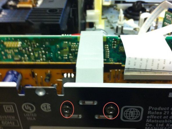
Remove two screws shown in the second image. Remove the gray connector on top of the input board.
-
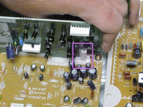
Next, use a flat head screwdriver to assist you in prying the right clip while simultaneously pulling up on the input board. Unclip the component from the logic board.
crwdns2944171:0crwdnd2944171:0crwdnd2944171:0crwdnd2944171:0crwdne2944171:0