crwdns2933423:0crwdne2933423:0

Mini Digital Oszilloskop Lötbausatz

crwdns2936315:0crwdne2936315:0
crwdns2936319:0crwdne2936319:0
crwdns2931653:011crwdne2931653:0
Mini Digital Oscilloscope DIY Soldering Kit Assembly: crwdns2935265:00crwdnd2935265:01crwdnd2935265:03crwdne2935265:0 Mini Digital Oscilloscope DIY Soldering Kit Assembly: crwdns2935265:00crwdnd2935265:02crwdnd2935265:03crwdne2935265:0 Mini Digital Oscilloscope DIY Soldering Kit Assembly: crwdns2935265:00crwdnd2935265:03crwdnd2935265:03crwdne2935265:0
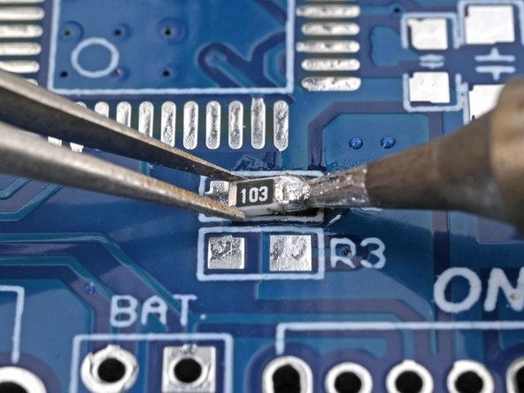
  • Place the smaller 10 kΩ resistor (labeled 103) in the outline labeled R2 on the board.

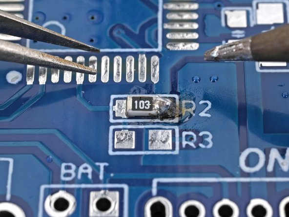
  • Press the soldering iron's tip onto the edge of the solder pad while holding the resistor in its outline, so that its end caps (the shiny parts) are resting on the circuit board's pads.

  • Remove the iron, then remove the tweezers once the solder has cooled.

Platziere den kleineren 10 kΩ Widerstand (mit der Markierung 103) in den mit R2 beschrifteten Umriss auf der Leiterplatte.

Halte den Widerstand auf dem Umriss fest und drücke gleichzeitig die Lötspitze auf die Kante der Lötstelle, so dass die (glänzenden) Enden des Widerstands auf den Lötstellen liegen.

Entferne den Lötkolben, wenn das Lötzinn abgekühlt ist auch die Pinzette.

crwdns2944171:0crwdnd2944171:0crwdnd2944171:0crwdnd2944171:0crwdne2944171:0