crwdns2935425:04crwdne2935425:0
crwdns2931653:04crwdne2931653:0

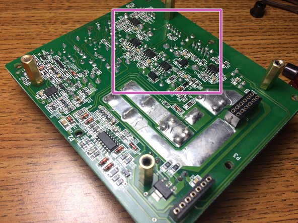


Amplifier in depth
-
Crossover / Gain
-
Power Supply and output FET's
-
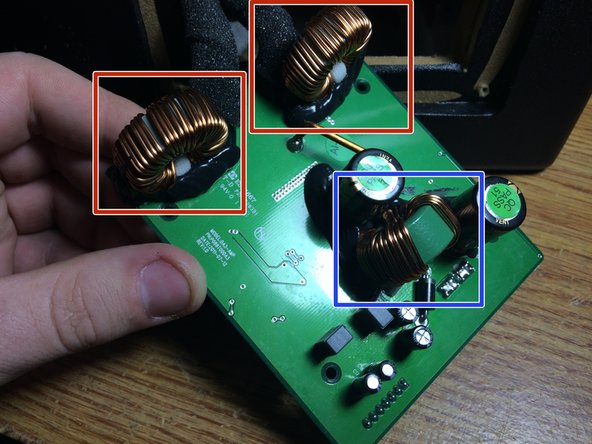
Power Supply Transformer
-
Output Filters
-
The 2 boards are held together by 4 screws on the edges of the PCB, gently pull them apart, they will only be held together by pin headers. Here you can see the 2 output filters and the power supply step up transformer
-
The board with the FEMALE pin headers is the front board with the plugs on it. the crossover network consists of JRC 4850's
crwdns2944171:0crwdnd2944171:0crwdnd2944171:0crwdnd2944171:0crwdne2944171:0