crwdns2942213:0crwdne2942213:0
-
crwdns2935201:0crwdne2935201:0 crwdns2935203:0crwdne2935203:0
-
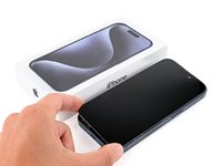
Unplug all cables from your phone.
-
Hold the power and either volume button and slide to power off your phone.
-
-
crwdns2935201:0crwdne2935201:0 crwdns2935203:0crwdne2935203:0
-
If your screen or back glass is cracked, lay overlapping strips of packing tape over the glass to protect yourself and make disassembly easier.
-
-
crwdns2935201:0crwdne2935201:0 crwdns2935203:0crwdne2935203:0
-
Measure 3 mm from the tip and mark the opening pick with a permanent marker.
-
-
crwdns2935201:0crwdne2935201:0 crwdns2935203:0crwdne2935203:0
-
Use a P2 pentalobe screwdriver to remove the two 7 mm‑long screws on either side of the charging port.
-
-
crwdns2935201:0crwdne2935201:0 crwdns2935203:0crwdne2935203:0
-
Use a hair dryer or heat gun to heat the bottom edge of the screen until it's hot to the touch.
-
-
crwdns2935201:0crwdne2935201:0 crwdns2935203:0crwdne2935203:0
-
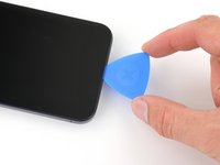
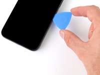
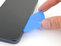
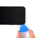
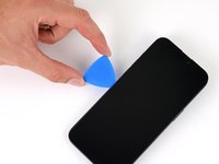
Apply a suction handle to the bottom edge of the screen.
-
Pull up on the handle with a strong, steady force to create a gap between the screen and the frame.
-
Insert the tip of an opening pick into the gap.
-
-
crwdns2935201:0crwdne2935201:0 crwdns2935203:0crwdne2935203:0
-
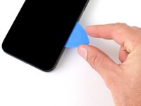
There are two delicate cables connecting the screen to the phone: one just above the action button, and the other near the middle of the left edge.
-
There are multiple spring contacts around the perimeter of the phone. Be extra careful not to insert your pick deeper than suggested in these locations to avoid bending the contacts.
-
-
crwdns2935201:0crwdne2935201:0 crwdns2935203:0crwdne2935203:0
-
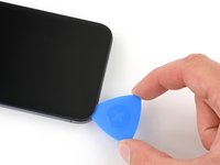
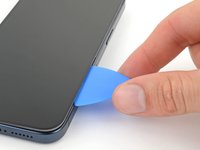
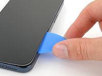
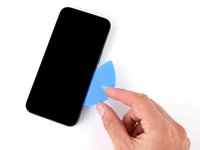
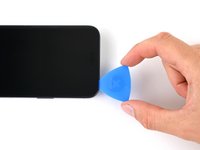
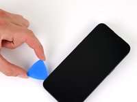
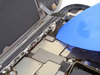
Slide your pick back and forth along the bottom edge to separate the adhesive.
-
Leave your pick inserted in the bottom right corner to prevent the adhesive from re-sealing.
-
-
crwdns2935201:0crwdne2935201:0 crwdns2935203:0crwdne2935203:0
-
Heat the right edge of the screen until it's hot to the touch.
-
-
-
crwdns2935201:0crwdne2935201:0 crwdns2935203:0crwdne2935203:0
-
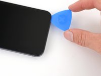
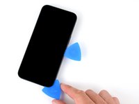
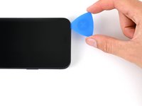
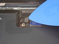
Slide your pick around the bottom right corner of the screen and toward the power button until you feel a hard stop at a clip securing the screen.
-
Rotate your pick so the flat edge is under the screen.
-
-
crwdns2935201:0crwdne2935201:0 crwdns2935203:0crwdne2935203:0
-
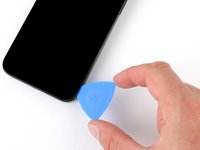
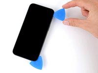
Twist the pick to increase the gap between the screen and the frame until the right clip releases.
-
Insert a second opening pick to the right of the first pick.
-
-
crwdns2935201:0crwdne2935201:0 crwdns2935203:0crwdne2935203:0
-
Slide the first pick back to the bottom right corner of the screen.
-
Slide the second pick to the top right corner of the screen to separate the adhesive.
-
Leave these picks inserted to prevent the adhesive from resealing.
-
-
crwdns2935201:0crwdne2935201:0 crwdns2935203:0crwdne2935203:0
-
Heat the top edge of the screen until it's hot to the touch.
-
-
crwdns2935201:0crwdne2935201:0 crwdns2935203:0crwdne2935203:0
-
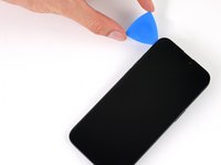
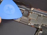
Slide your pick around the top right corner and along the top edge to release the two clips and adhesive securing it.
-
-
crwdns2935201:0crwdne2935201:0 crwdns2935203:0crwdne2935203:0
-
Heat the left edge of the screen until it's hot to the touch.
-
-
crwdns2935201:0crwdne2935201:0 crwdns2935203:0crwdne2935203:0
-
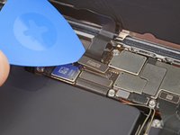
Rotate your pick around the top left corner of the screen.
-
Slide your pick to the bottom left corner of the screen to separate the adhesive.
-
-
crwdns2935201:0crwdne2935201:0 crwdns2935203:0crwdne2935203:0
-
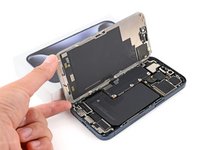
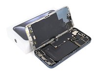
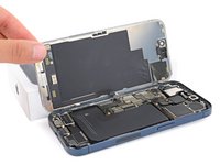
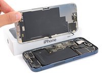
Place a small box or stack of books to the left of your phone so you can prop up the screen while disconnecting its cables.
-
Swing up the right edge of the screen like the front cover of a book.
-
Prop up the screen so you can access its cables without straining them.
-
-
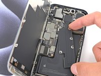
crwdns2935201:0crwdne2935201:0 crwdns2935203:0crwdne2935203:0
-
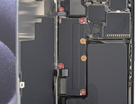
Use a Y000 screwdriver to remove the six screws securing the logic board cover:
-
Four 1.6 mm‑long screws
-
Two 1.3 mm‑long screws
-
-
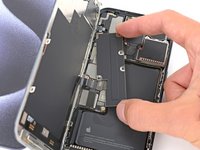
crwdns2935201:0crwdne2935201:0 crwdns2935203:0crwdne2935203:0
-
Rotate the bottom of the logic board cover counterclockwise and slide the top left corner out from under the ambient light sensor cable to remove it.
-
-
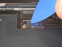
crwdns2935201:0crwdne2935201:0 crwdns2935203:0crwdne2935203:0
-
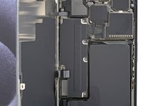
Use the tip of an opening pick to pry up and disconnect the battery press connector from the bottom right corner of the logic board.
-
-
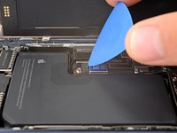
crwdns2935201:0crwdne2935201:0 crwdns2935203:0crwdne2935203:0
-
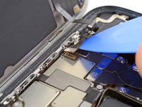
Use the tip of an opening pick to pry up and disconnect the screen cable from the center of the logic board.
-
-
crwdns2935201:0crwdne2935201:0 crwdns2935203:0crwdne2935203:0
-
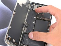
Gently slide the tip of an opening pick under the ambient light sensor cable near the top left corner of the logic board.
-
Lift the cable to disconnect it.
-
-
crwdns2935201:0crwdne2935201:0 crwdns2935203:0crwdne2935203:0
-
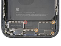
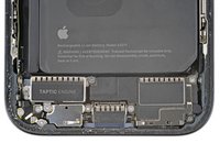
Use a Phillips #000 screwdriver to remove the four screws securing the loudspeaker:
-
One 2.7 mm‑long screw
-
Three 2 mm‑long screws
-
-
crwdns2935201:0crwdne2935201:0 crwdns2935203:0crwdne2935203:0
-
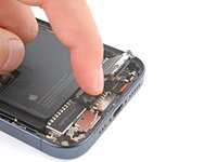
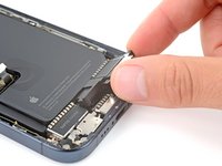
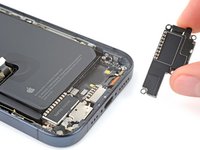
Lift the bottom edge of the loudspeaker until you can grab it with your fingers.
-
Peel the loudspeaker from the plastic buffer on its top edge and remove it.
-


crwdns2935221:0crwdne2935221:0
crwdns2935229:03crwdne2935229:0

