crwdns2942213:0crwdne2942213:0
-
crwdns2935201:0crwdne2935201:0 crwdns2935203:0crwdne2935203:0
-
Unplug all cables from your phone.
-
Hold the power and either volume button and slide to power off your phone.
-
-
crwdns2935201:0crwdne2935201:0 crwdns2935203:0crwdne2935203:0
-
If your screen or back glass is cracked, lay overlapping strips of packing tape over the glass to protect yourself and make disassembly easier.
-
-
crwdns2935201:0crwdne2935201:0 crwdns2935203:0crwdne2935203:0
-
Measure 3 mm from the tip and mark the opening pick with a permanent marker.
-
-
crwdns2935201:0crwdne2935201:0 crwdns2935203:0crwdne2935203:0
-
Use a P2 pentalobe screwdriver to remove the two 7 mm‑long screws on either side of the charging port.
-
-
crwdns2935201:0crwdne2935201:0 crwdns2935203:0crwdne2935203:0
-
Use a hair dryer or heat gun to heat the bottom edge of the screen until it's hot to the touch.
-
-
crwdns2935201:0crwdne2935201:0 crwdns2935203:0crwdne2935203:0
-
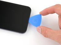
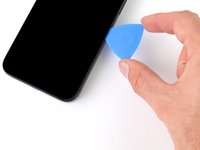
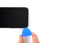
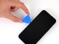
Apply a suction handle to the bottom edge of the screen.
-
Pull up on the handle with a strong, steady force to create a gap between the screen and the frame.
-
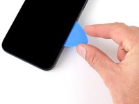
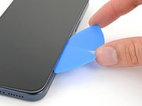
Insert the tip of an opening pick into the gap.
-
-
crwdns2935201:0crwdne2935201:0 crwdns2935203:0crwdne2935203:0
-
There are two delicate cables connecting the screen to the phone: one just above the action button, and the other near the middle of the left edge.
-
There are multiple spring contacts around the perimeter of the phone. Be extra careful not to insert your pick deeper than suggested in these locations to avoid bending the contacts.
-
-
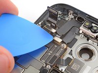
crwdns2935201:0crwdne2935201:0 crwdns2935203:0crwdne2935203:0
-
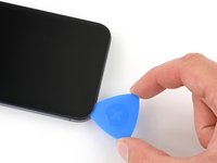
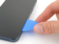
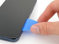
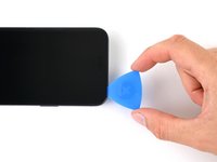
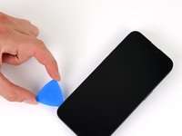
Slide your pick back and forth along the bottom edge to separate the adhesive.
-
Leave your pick inserted in the bottom right corner to prevent the adhesive from re-sealing.
-
-
crwdns2935201:0crwdne2935201:0 crwdns2935203:0crwdne2935203:0
-
Heat the right edge of the screen until it's hot to the touch.
-
-
crwdns2935201:0crwdne2935201:0 crwdns2935203:0crwdne2935203:0
-
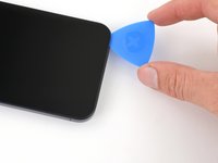
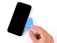
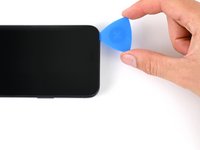
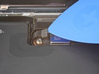
Slide your pick around the bottom right corner of the screen and toward the power button until you feel a hard stop at a clip securing the screen.
-
Rotate your pick so the flat edge is under the screen.
-
-
crwdns2935201:0crwdne2935201:0 crwdns2935203:0crwdne2935203:0
-
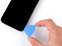
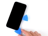
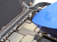
Twist the pick to increase the gap between the screen and the frame until the right clip releases.
-
Insert a second opening pick to the right of the first pick.
-
-
-
crwdns2935201:0crwdne2935201:0 crwdns2935203:0crwdne2935203:0
-
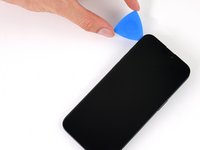
Slide the first pick back to the bottom right corner of the screen.
-
Slide the second pick to the top right corner of the screen to separate the adhesive.
-
Leave these picks inserted to prevent the adhesive from resealing.
-
-
crwdns2935201:0crwdne2935201:0 crwdns2935203:0crwdne2935203:0
-
Heat the top edge of the screen until it's hot to the touch.
-
-
crwdns2935201:0crwdne2935201:0 crwdns2935203:0crwdne2935203:0
-
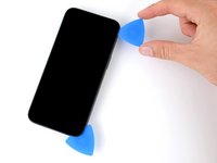
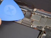
Slide your pick around the top right corner and along the top edge to release the two clips and adhesive securing it.
-
-
crwdns2935201:0crwdne2935201:0 crwdns2935203:0crwdne2935203:0
-
Heat the left edge of the screen until it's hot to the touch.
-
-
crwdns2935201:0crwdne2935201:0 crwdns2935203:0crwdne2935203:0
-
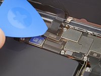
Rotate your pick around the top left corner of the screen.
-
Slide your pick to the bottom left corner of the screen to separate the adhesive.
-
-
crwdns2935201:0crwdne2935201:0 crwdns2935203:0crwdne2935203:0
-
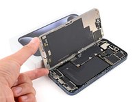
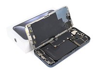
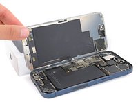
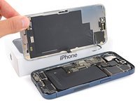
Place a small box or stack of books to the left of your phone so you can prop up the screen while disconnecting its cables.
-
Swing up the right edge of the screen like the front cover of a book.
-
Prop up the screen so you can access its cables without straining them.
-
-
crwdns2935201:0crwdne2935201:0 crwdns2935203:0crwdne2935203:0
-
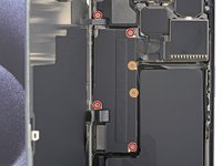
Use a Y000 screwdriver to remove the six screws securing the logic board cover:
-
Four 1.6 mm‑long screws
-
Two 1.3 mm‑long screws
-
-
crwdns2935201:0crwdne2935201:0 crwdns2935203:0crwdne2935203:0
-
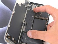
Rotate the bottom of the logic board cover counterclockwise and slide the top left corner out from under the ambient light sensor cable to remove it.
-
-
crwdns2935201:0crwdne2935201:0 crwdns2935203:0crwdne2935203:0
-
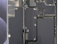
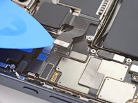
Use the tip of an opening pick to pry up and disconnect the battery press connector from the bottom right corner of the logic board.
-
-
crwdns2935201:0crwdne2935201:0 crwdns2935203:0crwdne2935203:0
-
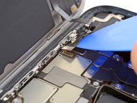
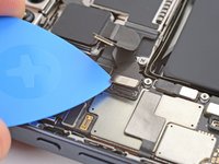
Use the tip of an opening pick to pry up and disconnect the screen cable from the center of the logic board.
-
-
crwdns2935201:0crwdne2935201:0 crwdns2935203:0crwdne2935203:0
-
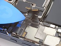
Gently slide the tip of an opening pick under the ambient light sensor cable near the top left corner of the logic board.
-
Lift the cable to disconnect it.
-
-
crwdns2935201:0crwdne2935201:0 crwdns2935203:0crwdne2935203:0
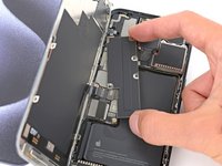
-
Use the tip of an opening pick to pry up and disconnect the three rear camera press connectors from the top right of the logic board.
-
-
crwdns2935201:0crwdne2935201:0 crwdns2935203:0crwdne2935203:0
-
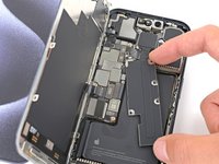
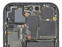
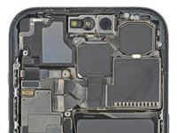
Use a Phillips #000 screwdriver to remove the three screws securing the rear cameras:
-
One 3.8 mm‑long screw
-
One 3.2 mm‑long screw
-
One 2.8 mm‑long screw
-
-
crwdns2935201:0crwdne2935201:0 crwdns2935203:0crwdne2935203:0
-
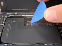
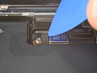
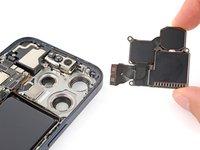
Insert the point of a spudger between the top right corner of the rear cameras and frame.
-
Pry up until you can grab the rear cameras with your fingers.
-
Remove the rear cameras.
-
-
crwdns2935201:0crwdne2935201:0 crwdns2935203:0crwdne2935203:0
crwdns2935267:0crwdne2935267:0Standoff Screwdriver for iPhones$5.49-
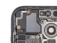
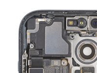
Use a Phillips #000 screwdriver to remove the 2 mm‑long screw securing the top of the earpiece speaker.
-
Use a standoff screwdriver to remove the remaining screw securing the bottom left corner of the earpiece speaker.
-
-
crwdns2935201:0crwdne2935201:0 crwdns2935203:0crwdne2935203:0
-
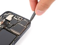
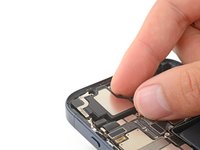
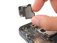
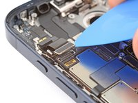
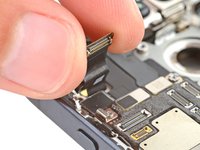
Use the tip of an opening pick to disconnect the microphone press connector from the top left corner of the logic board.
-
Lift the cable out of the way so you can access the two press connectors on the logic board's top edge.
-
-
crwdns2935201:0crwdne2935201:0 crwdns2935203:0crwdne2935203:0
-
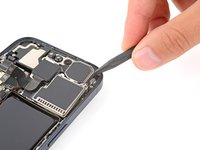
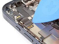
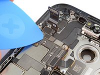
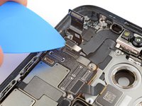
Use the tip of an opening pick to pry up and disconnect the front sensors and front camera press connectors from the top edge of the logic board.
-


crwdns2935221:0crwdne2935221:0
crwdns2935229:02crwdne2935229:0


crwdns2947410:01crwdne2947410:0
with ios 18, can you use the repair assistant tool to fix faceid? if not is there some sort of device i can use to pair the logic board with the faceid? if not, is my best bet for the front camera and faceid to work again just sending it in to apple for repairs?