crwdns2933423:0crwdne2933423:0

crwdns2931315:0crwdnd2931315:0crwdne2931315:0

crwdns2942213:0crwdne2942213:0

  1. crwdns2935201:0crwdne2935201:0 crwdns2935203:0crwdne2935203:0

    : crwdns2935265:01crwdnd2935265:01crwdnd2935265:01crwdne2935265:0
    • Lay your iMac front side down on a table with the lower edge facing yourself.

    • Loosen the single Phillips screw in the center of the access door.

    • This screw is captive in the access door.

    • Remove the access door from your iMac.

  2. crwdns2935201:0crwdne2935201:0 crwdns2935203:0crwdne2935203:0

    : crwdns2935265:02crwdnd2935265:01crwdnd2935265:02crwdne2935265:0 : crwdns2935265:02crwdnd2935265:02crwdnd2935265:02crwdne2935265:0
    crwdns2935267:0crwdne2935267:0
    Heavy-Duty Suction Cups (Pair)
    $14.95
    crwdns2942207:0crwdne2942207:0
    • The glass panel is fixed onto the front bezel with fourteen magnets around its perimeter.

    • Stick two suction cups to opposing corners of the glass panel.

    • To attach the suction cups we sell, first position the suction cup with the movable handle parallel to the face of the glass panel. While lightly holding the suction cup against the glass, raise the movable handle until it is parallel with the other handle.

    • If your suction cups refuse to stick, try cleaning both the glass panel and the suction cup with a mild solvent.

  3. crwdns2935201:0crwdne2935201:0 crwdns2935203:0crwdne2935203:0

    : crwdns2935265:03crwdnd2935265:01crwdnd2935265:01crwdne2935265:0
    • Gently pull the glass panel straight up off the iMac.

    • The glass panel has several positioning pins around its perimeter. To avoid shearing these pins off the glass panel, be sure to only pull straight up during removal.

    • Be meticulous about cleaning the LCD and the inside face of the glass panel before reinstallation, as any fingerprints or dust trapped inside will be annoyingly visible when the display is on.

    • When replacing the glass, be sure there's nothing between the glass and the frame. Stray cables could be damaged or crack the glass.

  4. crwdns2935201:0crwdne2935201:0 crwdns2935203:0crwdne2935203:0

    : crwdns2935265:04crwdnd2935265:01crwdnd2935265:01crwdne2935265:0
    • Remove the following 12 screws securing the front bezel to the rear case:

    • Eight 13 mm T8 Torx.

    • Four 25 mm T8 Torx.

    • On the 24" iMac Intel Model A1225, the bottom center two screws are long (26mm), four on sides (two left, two right) are medium (18mm), and the remaining 6 (four top, two bottom corners) are short (14mm).

  5. crwdns2935201:0crwdne2935201:0 crwdns2935203:0crwdne2935203:0

    : crwdns2935265:05crwdnd2935265:01crwdnd2935265:02crwdne2935265:0 : crwdns2935265:05crwdnd2935265:02crwdnd2935265:02crwdne2935265:0
    • The front bezel is still attached to the iMac by the microphone cable.

    • Gently lift the front bezel from its top edge off the rear case.

    • Once the top edge of the front bezel has cleared the rear case, rotate the front bezel toward the stand and lift it off the rear case.

    • Rotate the front bezel away from the rest of the device and lay it above the top edge of the iMac.

    • When reinstalling the front bezel, start at the lower edge and make sure it is flush with the rear case before lowering the top edge onto the iMac.

  6. crwdns2935201:0crwdne2935201:0 crwdns2935203:0crwdne2935203:0

    : crwdns2935265:06crwdnd2935265:01crwdnd2935265:01crwdne2935265:0
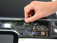
    • Disconnect the microphone cable connector, removing tape as necessary.

    • For the front bezel to sit properly, be sure to tuck the microphone cable and connector into the void next to the camera board.

  7. crwdns2935201:0crwdne2935201:0 crwdns2935203:0crwdne2935203:0

    : crwdns2935265:07crwdnd2935265:01crwdnd2935265:03crwdne2935265:0 : crwdns2935265:07crwdnd2935265:02crwdnd2935265:03crwdne2935265:0 : crwdns2935265:07crwdnd2935265:03crwdnd2935265:03crwdne2935265:0
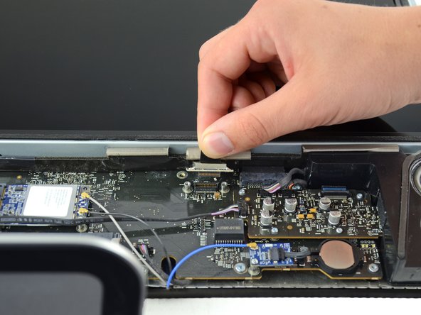
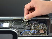
    • Remove the two 5.3 mm T6 torx screws from the LCD connector.

    • Firmly grasp the pull tab on top of the connector and pull it straight up out of its port.

    • Make sure that you are pulling the tab and not the connector cable.

  8. crwdns2935201:0crwdne2935201:0 crwdns2935203:0crwdne2935203:0

    : crwdns2935265:08crwdnd2935265:01crwdnd2935265:01crwdne2935265:0
    • Remove the eight T8 Torx screws securing the display panel to the rear case.

    • The iMac shown is a 20" model, but the screw locations should be approximately correct.

  9. crwdns2935201:0crwdne2935201:0 crwdns2935203:0crwdne2935203:0

    : crwdns2935265:09crwdnd2935265:01crwdnd2935265:03crwdne2935265:0 : crwdns2935265:09crwdnd2935265:02crwdnd2935265:03crwdne2935265:0 : crwdns2935265:09crwdnd2935265:03crwdnd2935265:03crwdne2935265:0
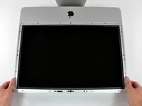
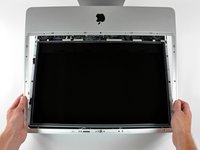
    • Place your hands on either side of the bottom of the display panel, and lift it up enough that you can reach the connectors inside.

    • Do not try to remove the display panel completely as it is still connected to the rest of the device.

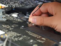
    • While holding the display panel up with one hand, locate and remove the display thermal sensor cable from its connector.

  10. crwdns2935201:0crwdne2935201:0 crwdns2935203:0crwdne2935203:0

    : crwdns2935265:010crwdnd2935265:01crwdnd2935265:02crwdne2935265:0 : crwdns2935265:010crwdnd2935265:02crwdnd2935265:02crwdne2935265:0
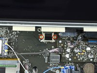
    • While still holding the display panel up, use two fingers to firmly push down on the power supply cable connector from its socket.

    • Be very careful not to touch the exposed face of the power supply to avoid electric shock from the many large capacitors attached to the other side of the board.

  11. crwdns2935201:0crwdne2935201:0 crwdns2935203:0crwdne2935203:0

    : crwdns2935265:011crwdnd2935265:01crwdnd2935265:01crwdne2935265:0
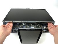
    • Lift and remove the display panel from the device.

  12. crwdns2935201:0crwdne2935201:0 crwdns2935203:0crwdne2935203:0

    : crwdns2935265:012crwdnd2935265:01crwdnd2935265:02crwdne2935265:0 : crwdns2935265:012crwdnd2935265:02crwdnd2935265:02crwdne2935265:0
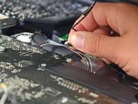
    • Peel off the tape holding the optical drive in place.

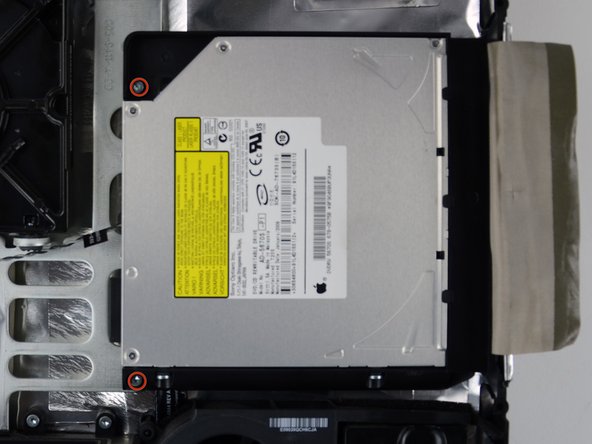
    • Remove the two 7.1 mm T10 torx screws.

  13. crwdns2935201:0crwdne2935201:0 crwdns2935203:0crwdne2935203:0

    : crwdns2935265:013crwdnd2935265:01crwdnd2935265:03crwdne2935265:0 : crwdns2935265:013crwdnd2935265:02crwdnd2935265:03crwdne2935265:0 : crwdns2935265:013crwdnd2935265:03crwdnd2935265:03crwdne2935265:0
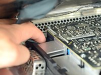
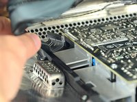
    • Firmly grab the optical drive connector and pull it straight out of the optical drive.

    • Remove the optical drive from the device.

  14. crwdns2935201:0crwdne2935201:0 crwdns2935203:0crwdne2935203:0

    : crwdns2935265:014crwdnd2935265:01crwdnd2935265:01crwdne2935265:0
    • Remove the piece of foam tape covering the optical drive thermal sensor.

  15. crwdns2935201:0crwdne2935201:0 crwdns2935203:0crwdne2935203:0

    : crwdns2935265:015crwdnd2935265:01crwdnd2935265:01crwdne2935265:0
    • To remove the optical drive thermal sensor, use the tip of a spudger to lift the center finger of the thermal sensor bracket while applying slight tension to the thermal sensor cable.

    • If the thermal sensor is stuck to the optical drive, skip to the next step.

  16. crwdns2935201:0crwdne2935201:0 crwdns2935203:0crwdne2935203:0

    : crwdns2935265:016crwdnd2935265:01crwdnd2935265:01crwdne2935265:0
    • Use the flat end of a spudger to pry the optical drive thermal sensor bracket up off the adhesive securing it to the optical drive.

    • If the adhesive gets dirty or will not stick to your new optical drive, place some double-sided tape under the two semicircular ears of the thermal sensor bracket.

  17. crwdns2935201:0crwdne2935201:0 crwdns2935203:0crwdne2935203:0

    : crwdns2935265:017crwdnd2935265:01crwdnd2935265:01crwdne2935265:0
    • Use a spudger to remove the small piece of EMI foam from the bottom of the optical drive.

    • Don't forget to transfer this to your new drive.

  18. crwdns2935201:0crwdne2935201:0 crwdns2935203:0crwdne2935203:0

    : crwdns2935265:018crwdnd2935265:01crwdnd2935265:01crwdne2935265:0
    • Peel the EMI tape off the optical drive.

    • Don't forget to transfer this to your new optical drive.

  19. crwdns2935201:0crwdne2935201:0 crwdns2935203:0crwdne2935203:0

    : crwdns2935265:019crwdnd2935265:01crwdnd2935265:02crwdne2935265:0 : crwdns2935265:019crwdnd2935265:02crwdnd2935265:02crwdne2935265:0
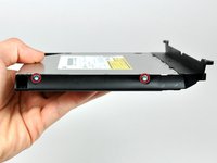
    • Remove the two T10 Torx screws from both sides of the optical drive (four screws total).

  20. crwdns2935201:0crwdne2935201:0 crwdns2935203:0crwdne2935203:0

    : crwdns2935265:020crwdnd2935265:01crwdnd2935265:01crwdne2935265:0
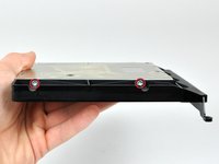
    • Use the tip of a spudger to press each of the optical drive bracket tabs out of their slots on the bottom of the optical drive.

  21. crwdns2935201:0crwdne2935201:0 crwdns2935203:0crwdne2935203:0

    : crwdns2935265:021crwdnd2935265:01crwdnd2935265:02crwdne2935265:0 : crwdns2935265:021crwdnd2935265:02crwdnd2935265:02crwdne2935265:0
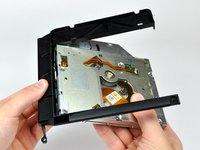
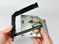
    • Rotate the optical drive bracket slightly away from the optical drive.

    • Pull the optical drive bracket away from the open end of the optical drive, minding any tabs that may get caught.

    • If you have a disk or anything else stuck inside your optical drive, we have a guide to fix it.

crwdns2935217:0crwdne2935217:0

crwdns2935229:014crwdne2935229:0

Brittany McCrigler

crwdns2935283:003/05/12crwdne2935283:0

88,930 crwdns2915208:0crwdne2915208:0

crwdns2935297:0131crwdne2935297:0

crwdns2915084:0crwdne2915084:0

iFixit crwdns2935289:0iFixitcrwdne2935289:0

Staff

crwdns2931471:0135crwdne2931471:0

crwdns2935297:016,718crwdne2935297:0

crwdns2944067:00crwdne2944067:0

crwdns2917038:0crwdne2917038:0

crwdns2936625:0crwdne2936625:0:

crwdns2936751:024crwdne2936751:0 0

crwdns2936753:07crwdne2936753:0 3

crwdns2936753:030crwdne2936753:0 22

crwdns2942667:0crwdne2942667:0 16,452