crwdns2915892:0crwdne2915892:0
iMac Intel 24" EMC 2267 CPU replacement
crwdns2942213:0crwdne2942213:0
-
-
Retournez votre iMac sur une table en plaçant le bas de l'appareil face à vous.
-
Desserrez l'unique vis Phillips au centre de la trappe d'accès.
-
Retirez la trappe d'accès de votre iMac.
-
-
-
Collez une ventouse au niveau d'un angle de la vitre et une autre ventouse à l'angle opposé.
A good alternative to the two heavy duty suction cups is a regular household plunger.
Also, 2" wide packing tape. Maybe a 6 or 8" piece, folded in the middle to give you say, a 1-2" "handle". Make a pair of these. They look like a capital T but with a short vertical part (the handle), and a wide top I the sticky wings). Get the good 3M tape, it's strong, and it peels off clean without leaving any glue from the screen.
for me one household plunger did the trick!
-
-
-
Soulevez délicatement la vitre de l'iMac.
-
Lors du remplacement de la vitre, assurez-vous qu'il n'y a rien entre la vitre et le châssis. Les nappes pourraient s'abîmer ou fissurer la vitre.
Another approach that worked for us was to get 4 small plastic wedges (the kind used in iphone screen replacements). Working one corner at a time you can use a cheap suction cup to pry just that corner up enough to slide the wedge in. Then proceed to the next then next, etc. Once all 4 have the wedges under them the glass should be away from the body all the way around, then just carefully lift it the rest of the way up.
-
-
-
Retirez les 12 vis suivantes par lesquelles le cadre avant est fixé au boîtier arrière :
-
Huit vis Torx T8 13 mm.
-
Quatre vis Torx T8 25 mm.
I would strongly suggest taping the screws down on a piece of paper towel or cloth in the same order you take them out, as there are different lengths in no particular order and they don't all fit into just any hole. Unless you keep track of which hole each screw belongs, there is no other way of knowing. I stress taping because I didn't tape mine down and after bumping the table I was working on they scattered, leaving me to guess.
Even better, use an ice cube tray to keep the screws from each step together.
how about using the magnets near the screws to keep their positions?
I use an 18 count egg carton (or two) and label each egg slot with a Sharpie. Works great.
As a rule with iFixit repairs, for years I've been printing the guides, applying scotch magic tape near each picture (which allows me to reutilise the paper prints in the future), neatly putting the appropriate screw next to their picture and taping them down with scotch magic tape.
Even if I have to wait for spare parts, this allows me to neatly file the guide + screws in a copy safe and a binder (or in a cardboard filing box together with the rest of the parts) for later reassembly. Hardly any mistake possible...
I think the caption on the picture is wrong here for 24" iMacs - it says: "On the 24" iMac Intel Model A1225, the bottom center two screws are long (26mm), four on sides (two left, two right) are medium (18mm), and the remaining 6 (four top, two bottom corners) are short (14mm)." I think actually bottom centre two are long, then all the rest are medium apart from the two either side of the CD/DVD drive
I print out the steps. Get a roll of scotch tape ready. Every screw, or set of screws I remove, I lay on some tape, and then tape them to the number on the directions. Then you have each screw labeled, with direction, and in order, or reassembly. Just working backwards in the directions.
I agree with @HBloomfield’s comment overall, but to add to that comment, mine was a little different.
(2) Long: bottom center
(4) Medium: bottom left and right; on either side of the CD/DVD drive
(6) Short: everything else
Yes Jake I found the same with my iMac Model A1225.
Be careful with the thermal sensor wire so that it won't get under the second bottom screw from the left.
-
-
-
Soulevez avec précaution le bord supérieur du cadre avant hors du boîtier arrière.
-
Après avoir libéré le bord supérieur du cadre avant, faites pivoter ce dernier vers le support et sortez-le du boîtier arrière.
-
Pour accéder au reste de l'ordinateur, déplacez le cadre avant en le faisant pivoter et posez-le au-dessus du bord supérieur de l'iMac.
Contrary to the pictures, to lift the front bezel off, start at top of the computer screen lifting up while apply a little bit of pressure to the foam in the upper corners of the screen. This will give you the leverage needed to get the bezel to lift up. Be careful to not pull to fast, as the camera cable is still attached.
you'll need to add this step in all the other tutorials about iMac 20" EMC 2210, where it is missing ; they all jump from step 5 to step 6, which is a little annoying...
Easy way to remove bezel, insert the longest screws a quarter turn into the two top most edge screw slots. Use the screws as anchors to press against as you pull the bezel toward you. Then a simple twist to remove the screws, and the rest of the bezel comes off easy.
-
-
-
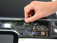
Débranchez le connecteur du câble du microphone, en retirant la bande adhésive si nécessaire.
During reinstallation of the LCD panel, be sure that the iSight microphone cable does not become trapped behind the panel.
I actually didn't have to remove the cable. With the iMac laying on its back, just rotate the front bezel (bottom edge rotating around top edge) so that it's laying upside down, above the iMac. When reassembling, just rotate back into place.
-
-
-
-
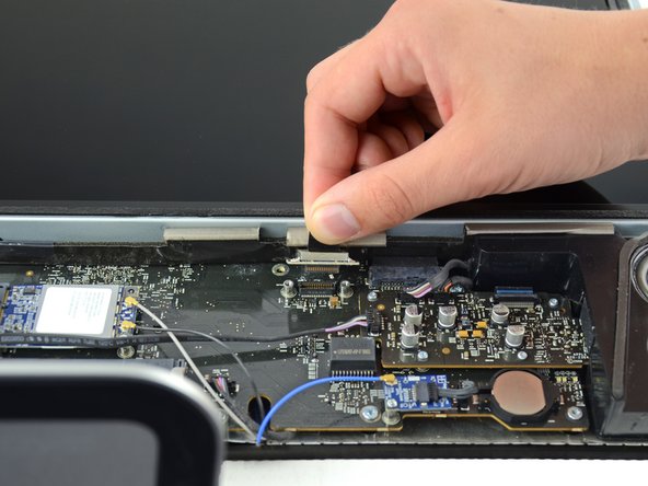
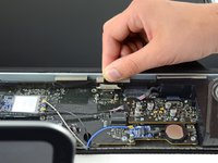
Retirez les deux vis Torx T6 5,3 mm du connecteur LCD.
-
Tenez fermement la languette sur le dessus du connecteur et tirez-la vers le haut pour sortir le connecteur de la prise.
remove the 8 screws (torx) that is holding the screen.
I actually had to use my 6H torx. my 4/5/6’s wouldn’t grab. Whether its from stripping or whatever the 6H worked fine.
I completely stripped one of the T6 screws. If you did too, they are M2 screws. An M2x6mm with a couple washers works fine.
When reassembling, it’s probably a smart move to reconnect this cable before putting the display-holding T8 screws in.
-
-
-
Retirez les huit vis Torx T8 qui fixent l'écran au boîtier arrière.
-
L'iMac que vous visualisez sur la photo est le 20'', mais l'emplacement des vis devrait être à peu près le même.
-
-
-
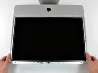
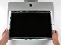
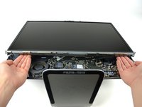
Placez une main de chaque côté en dessous de l'écran et soulevez-le suffisamment pour pouvoir accéder aux connecteurs à l'intérieur de l'ordinateur.
-
Tout en tenant l'écran d'une main, localisez et débranchez le câble du capteur thermique de l'écran de son connecteur.
Make sure you reconnect the cable for the thermal display sensor during reassembly. If you don't, the fans will be running at max speed and you might think it is from the drive thermal sensor afterwards (which is an issue some users have and which can be fixed in software).
I had great success with just propping the top edge of the LCD display up with a box about 8" long. By doing so, I didn't have to remove the thermal sensor wire or the power cable.
The thermal sensor connection is more of a pain than it seems. It's a cramped area and it's not clear when it's properly plugged in during reassembly. It may *feel* like it's in, but then pops free at the slightest touch. I guarantee that if as soon as you start up, fans running max speed instantly is the indication this is the issue. If you're ok with that, then fine, but otherwise, you'll have to pull it apart again.
Unplugging the thermal sensor connection is easier said than done, but using the spudger here is very
helpful
Brian Tsai has it RIGHT! I purchased the OWC SSD and bracket (NewerTech AdaptaDrive). Using the bracket box to support the LCD screen up on the upper left corner and getting adequate illumination it was really easy to change out the drive. Note - i used a knife to pop off the thermal sensor OFF THE DRIVE (not the PCB) as in Step 21, used the knife to pry off the connectors as in Step 16. I suspect you don’t even have to do Step 7.
-
-
-
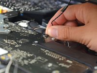
Tout en continuant de tenir l'écran, appliquez une pression vers le bas sur le connecteur du câble d'alimentation avec deux doigts afin de le débrancher de sa prise.
When putting this back together it can be extremely difficult to plug this cable back in without removing a guard that is held in by 2x T8 Torx screws just next to it.
I will suggest to remove the other end of the socket which is connected to the display panel. You can never imagine how difficult it will be to plug in on the main body, unless you know well about it.
I didn't realize these comments were HERE? Poor web design if you can't see comments in an obvious way. Step 10 will cause you the most trouble in reassembling the computer and I knew it as soon as I popped that connector out off the board. Its really f*cking hard to get that connector hooked back up in the way it should be and I have small hands. I managed to get it at least partly pushed in after several tries. Over all it took over half an hour to get it back in there right and scared the !@#$ out of me because I didn't think I could get it done. Those stupid little plastic things won't help you here, the connector really needs to be pushed hard to get it back in. I ended up using a big beefy screw driver for slotted screws, about a ten inch long screwdriver. I used the blade on each end of the connector and was able to give it a good hard push on one end, then pushed on the other end, slowly rocking the connector back into full flush contact. Be real careful you aren't pushing on the ribbon at all.
Having done this procedure 6+ times now, I can tell you it's much easier if, instead of holding the panel up by the "bottom" as illustrated in the guide, instead raise it by the "left" side. It gives you (me) much more room to get fingers behind the connector.
May have been obvious to some, but this little adjustment didn't jump out at me until the 2nd or 3rd rebuild.
There are four screws holding the power supply in place. Two different thread types so make note! Then lifting the power supply enough to easily plug the power cable back in is MUCH less of a problem. Then put the four screws back and proceed on.
That´s exactly how I managed reassembling this connector very easily: Open the four screws, that hold down the platine and then lift it up a little bit.
info -
It isn't that hard if you start by hold the display panel up perpendicular to the case on the side of this challenging connector. From here you'll be able to connect the cable, then follow through with the two other connectors (two screws on the last one). Worked great for me.
By far this was the most difficult cable to reconnect. I enlisted a second person to hold the display after I unscrewed the power supply (Torx 10, 4 screws) and was able to give my fingers adequate room to securely reattach it. There's no need to do this when disconnecting the power supply, but it would take more nimble fingers than mine to reattach it without loosening the power supply.
Do not remove this cable....! Too hard to get back there... I had to screw and lift up the whole platine to get the f**** cable back there....
EASIER IS:
# just remove the mic-cable (step6),the Thermal sensor (step9) the LCD-connector (step 10)...
# then let someone lift up (works also alone) the screen on the right side (there where Superdrive is)...
# remove Drive and Replace!!!!!
# Reconnect the easy cables....
agree! this cable is really tricky ...
Johann -
This step is TOTALLY UNNECESSARY on a 24" model!
Skip it; you have enough space to lift the panel.
You don't need to do this step at all - you can leave the panel connected to the circuit board while you replace the hard drive. I did this while replacing the drive on my 24" iMac, just resting the panel on a box I had put next to the iMac on my desk, so that the panel stayed at the same level but was just moved and rotated sideways, with the cable still connected.
I had great success with just propping the top edge of the LCD display up with a box about 8" long. By doing so, I didn't have to remove the thermal sensor wire or the power cable.
The power cable actually has a fair amount of play in it IF you peel back the thin black tape that affixes it to the LCD panel side to expose the power cable connector on the LCD side.
Note: SERIOUSLY:
- Disconnect the temp sensor from the iMac
- Lift up the screen from the RIGHT side (as if the iMac were standing up, facing you) to a vertical position
- Peel back the tape on the back of the LCD to expose the power supply connection
- Pull the connection from the LCD
- Attachment is the reverse
MUCH easier
-
-
-
Soulevez et retirez l'écran de l'appareil.
There is (what it looks like) a display ribbon cable attached that is hard to disconnect.
-
-
-
Commencez par suivre l'excellent guide de Jeff Dickson du step 2 jusqu'au step 9 (demontage de la logic board)
-
-
-
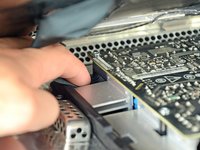
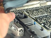
Retirer les stickers de preuve de garantie.
-
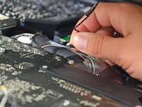
Débrancher le capteur de temperature CPU.
-
-
-
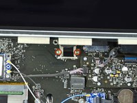
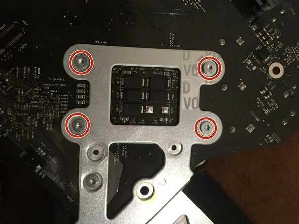
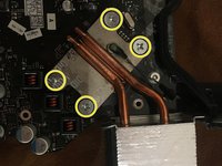
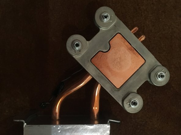
Dévisser les 4 vis radiateur a l'aide du tournevis Philips #2
-
Retourner la logic board
-
Finir de dévisser et retirer les 4 vis torx 8
-
-
-
Nettoyer le surplus de pate thermique à l'aide d'un chiffon propre et d'une solution alcoolique.
-
-
-
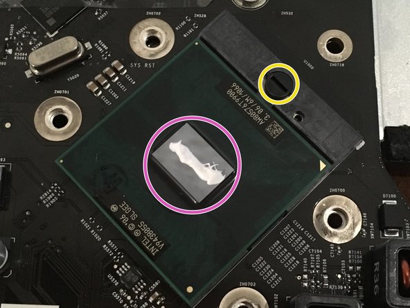
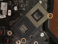
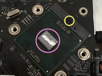
Dévisser d'un demi tour la vis de blocage du CPU à l'aide d'un petit tournevis plat.
-
Retirer délicatement le processeur en le tirant verticalement.
-
-
-
Aligner le nouveau processeur grâce au détrompeur.
-
Deposer le nouveau processeur verticalement dans son logement.
-
Revisser la vis de blocage d'un demi tour.
-
Deposer un peu de pâte thermique sur le centre du CPU.
You should put in the “Parts” section which, thermal paste we should use to fill in the thermal paste we wiped off.
Use Arctic Silver 5 — avoid the cheap alternatives (they’re not worth it).
-


To reassemble your device, follow the instructions in reverse order.
To reassemble your device, follow the instructions in reverse order.
crwdns2935221:0crwdne2935221:0
crwdns2935229:07crwdne2935229:0

crwdns2947410:01crwdne2947410:0
Anyone have any tips or advice as to what CPUs would work best?
The grid won't fall off by itself. You'll have to help it. Use the smallest screwdriver you have; the Torx 6 worked fine for me. It should enter in one of the many holes composing the grid. Use it as a lever to ploy the grid a little bit. You may catch it with your fingers and that's it.
Be carefull not to damage the hole by a too strong leverage.
Laurent - crwdns2934203:0crwdne2934203:0
much more safer to use duct tape, instead of torx 6. (glue it along the length of the grid and pull). it will loose instantly and smooth;)
Hofmann78rus - crwdns2934203:0crwdne2934203:0
Anyone know a guide to replace the plastic piece this screw connects to? I accidentally forgot this step - went to remove the front bezel and bent the plastic piece the access door connects to.
Jason Augustin - crwdns2934203:0crwdne2934203:0