crwdns2942213:0crwdne2942213:0
-
-
Make sure battery-lock is in the unlock position.
-
Slide button to the left.
-
-
-
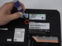
Remove the two 5.62 mm screws from the optical drive cover.
-
-
-
Remove the optical drive cover.
-
A plastic opening tool or a fingernail may be helpful in lifting it from its groove.
-
-
-
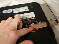
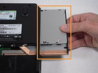
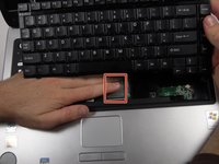
Using the inset divot, push the optical drive out of the laptop to remove.
-
-
-
Push the bottom left corner of the CD Drive until the drive protrudes from the case.
-
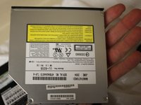
When a good amount of the CD Drive is showing on the right side, gently pull it out completely.
-
-
-
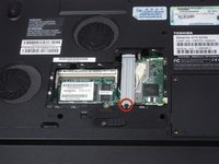
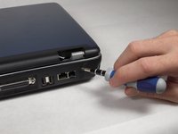
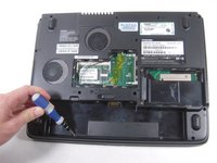
Remove the 5.75 mm screw from the cover panel.
-
-
-
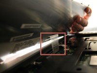
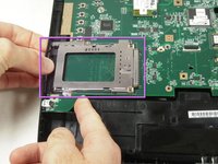
Lift up the cover panel using a plastic opening tool.
-
-
-
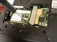
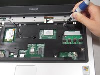
Remove the 5.64 mm screw from the bottom of the crossing bar.
-
Remove the crossing bar.
-
-
-
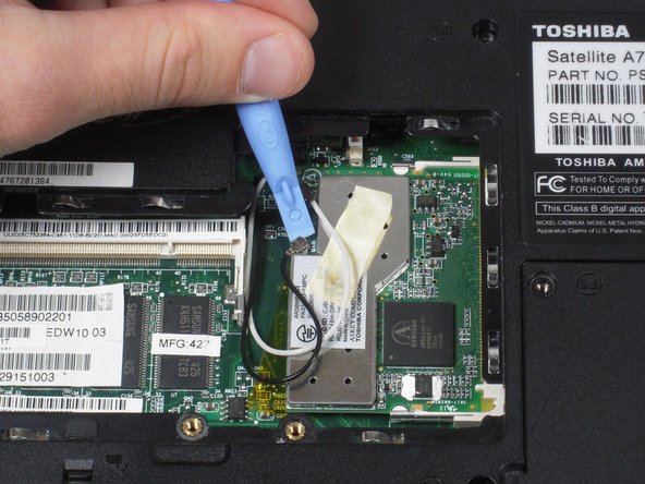
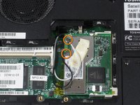
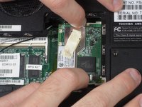
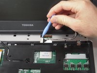
Use a plastic opening tool to disconnect the black and white antenna cable's connectors from the Wi-Fi card.
-
-
-
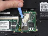
Use fingers to push the clips away from memory card.
-
-
-
-
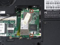
Use fingers to remove the Wi-Fi card.
-
-
-
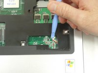
Use the plastic opening tool to lift up the top panel all the way along the keyboard until it loosens.
-
-
-
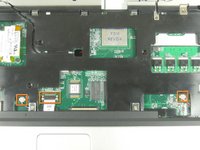
Remove the top panel by popping the panel out the top left socket, then do the same with the right side.
-
-
-
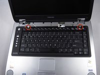
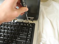
Remove the two 3.67 mm screws from the top corners of the keyboard.
-
-
-
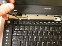
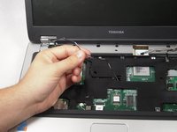
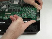
Use fingers to lift up the keyboard from the top.
-
-
-
Remove the cable connecting the keyboard with the motherboard.
-
Lift up and remove the keyboard.
-
-
-
Remove the 3.76mm screw from the ground wire.
-
-
-
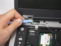
Use the plastic opening tool to remove the wire.
-
-
-
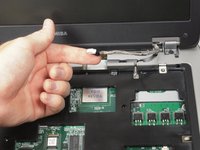
Gently pull the black and white wires out of the upper case.
-
-
-
Remove the 8.6 mm screw on left side of upper case.
-
-
-
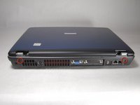
Remove two 8.6 mm screws on the back corners of the laptop.
-
-
-
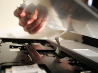
Lift up the display assembly to remove it.
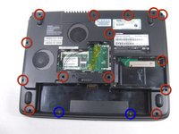
one of the 14 screws identified in the diagram of step 25 was previously removed with the CD drive
-
-
-
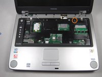
Use the Phillips screwdriver to remove the two 3.7 mm screws from the battery compartment.
-
Then remove the fourteen 8.6 mm screws from the bottom of the case.
There is one more not circled on the top left of this photo, left of the rubber foot.
-
-
-
Use the screwdriver to remove six 8.6 mm screws from the top of the case.
-
-
-
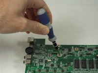
Use the plastic opening tool to remove the two speaker wire connectors and the trackpad connector from the motherboard.
-
-
-
With the plastic opening tool, pry around the entire laptop to separate the upper case.
-
-
-
Using the Phillips Screwdriver, remove the two 8.6 mm screws from the front edge of the motherboard.
-
-
-
Remove the four screws holding the ports to the rear panel using the 3/16" Wrench.
-
-
-
Lift up on the front edge of the motherboard while gently prying the case away from the ports on the right side of the computer.
-
Repeat with the left side.
-
-
-
Lift the motherboard's front edge up and then slide it forward.
-
-
-
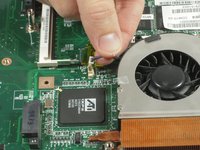
Remove cables connecting the fans with the motherboard.
-
-
-
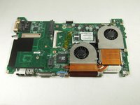
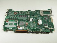
Turn over the motherboard.
-
Remove the four silver screws with a Phillips screwdriver.
-
-
-
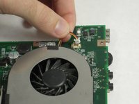
Turn over the motherboard.
-
Lift the fans up to remove them from the motherboard.
-


To reassemble your device, follow these instructions in reverse order.
To reassemble your device, follow these instructions in reverse order.
crwdns2935221:0crwdne2935221:0
crwdns2935229:05crwdne2935229:0
crwdns2915084:0crwdne2915084:0

Cal Poly, Team 4-43, Amido Fall 2010 crwdns2935289:0Cal Poly, Team 4-43, Amido Fall 2010crwdne2935289:0
CPSU-AMIDO-F10S4G43
crwdns2931471:05crwdne2931471:0
crwdns2935297:039crwdne2935297:0
crwdns2947412:02crwdne2947412:0
Thanks Garrett...
Your time and effort in putting this guide together is much appreciated (and helpful!)
Rick
I found this guide to be very helpful, well written and easy to follow.
Close up pics of any connectors, wires and cables that are disconnected help me a lot in that many of my projects have been previously attempted by others who have damaged or wrongly re-assembled the items.