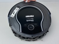
crwdns2915892:0crwdne2915892:0
Your robot navigates through a combination of random movements and sensors to guide it around a room. This guide will show you how to access two of these senors in the event that they fail and need to be replaced. Faulty senors will result in sporadic robot movement, more frequent collisions, and the robot eventually flashing error codes.
Remember to periodically clean all sensors with a dry microfiber cloth to keep your R75 performing properly.
crwdns2942213:0crwdne2942213:0
-
-
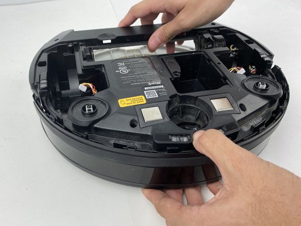
Flip the R75 over so that the underside is facing up.
-
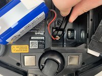
Using a Phillips #1 screwdriver, remove the 4mm screw in the battery cover.
-
Remove the battery cover.
-
-
-
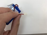
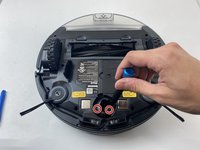
Slowly pull the white tabs outward to remove the battery.
Make sure to review how to appropriately use special bullets. Make sure to check throughout to remove “locate” steps, and instead, just go straight to the action.
-
-
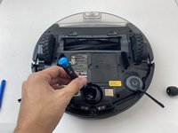
crwdns2935267:0crwdne2935267:0Tweezers$4.99
-
Push down on the tab of the battery connector using a set of tweezers and pull the connector away from the robot to free the wire.
-
Remove the battery from the device.
Here, you’re using tweezers, but you don’t indicate that in the guide steps. Instead of including the information in the special bullet, I would just integrate the tool into the actual procedure. Do you have pictures of you pushing the tab? Can they yank the wire, or do they need to pull gently? I would add a flipbook style action shot to make the procedure clearer in the pictures.
-
-
-
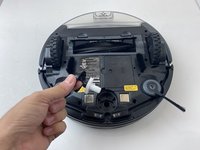
Push on the two tabs on the edge of the main brush cover and pull up to remove the cover.
I would add markup and action shots here. Which cover? Make sure to specifically identify device components.
-
-
-
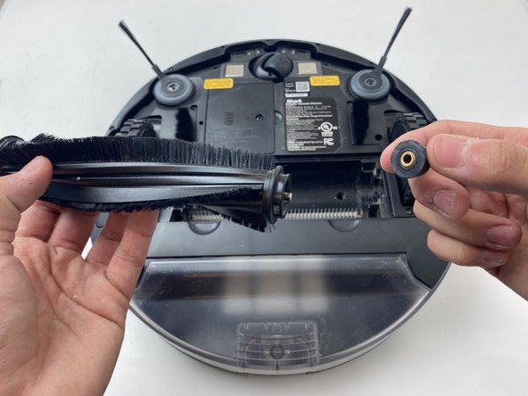
Pull the main brush slightly to the right to remove it from the compartment.
When will you know that you’ve pulled far enough to the right? When you say remove, do you need to lift the brush up? Do you have more action shots demonstrating this procedure?
Right. Mine does not budge, and I don’t want to break the mounts.
-
-
-
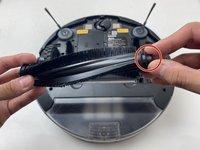
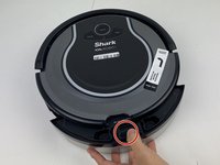
Remove the rubber end cap indicated by the red circle.
Be sure to check special bullets. Indicate how to remove the end cap.
-
-
-
Grab the side brushes by the plastic tab at the base of the bristles, and gently lift up.
The first step doesn’t seem necessary here. You can just include markup on the full shot to show the component you’re asking them to work on. Also, you don’t need to include cleaning/maintenance directions here, although you can include them in the introductions and/or the troubleshooting page.
-
-
-
-
Flip the R75 to its underside.
-
Make sure the R75 is shut off.
Here, the device was already oriented this way, so the directions on the side sensor with using this prerequisite make the procedure confusing. Make sure to read through all guides to make sure you don’t have these kinds of continuity errors. Also, include the battery replacement as a prerequisite for all guides, and use the system to include the prerequisites, rather than putting this information in the note.
-
-
-
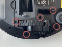
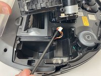
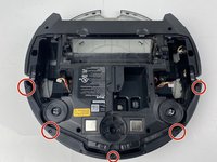
Using a Torx T15 screwdriver, remove the five screws from the drive wheel assembly.
-
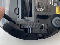
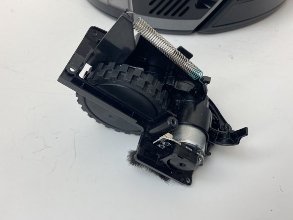
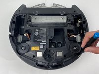
Carefully lift the drive wheel assembly from the wheel well by gently pulling up on the wheel.
Be sure to include a markup shot showing the location of the five screws. Remove locate steps in all guides. Indicate how to remove the wheel assembly in the guide text. Use caution bullets for caution notes.
What to do when the cable rips when taking wheel out?
-
-
-
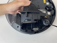
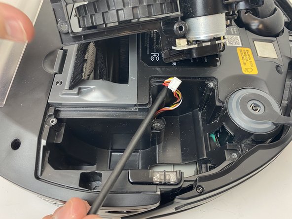
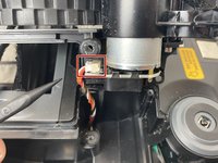
Flip the wheel assembly over and disconnect the cable connector on its underside.
-
Remove the drive wheel assembly.
Add markup. Remove all reassembly guide text. Indicate how to disconnect the cable, not just to do it.
-
-
-
Orient the device with the bottom facing up.
This photo is not helpful. Is removing the whole assembly correct procedure, or could it break the device?
-
-
-
Using a plastic opening tool, pry first one side of the wheel, then the other out of the caster.
-
Remove the wheel.
Note that you’re using a plastic opening tool, not a screwdriver. Be sure to appropriately identify tools. Proofread all guide text for clarity and end punctuation. For all remaining “remove” steps, if something can be done in multiple ways, then you need to indicate how. Remove is good for screws because there’s only one way to do that. For everything else, use more detail or a stronger verb.
-
-
-
Using a Torx TR9 screwdriver, remove both screws from the caster assembly beneath the wheel.
-
Pull the caster assembly up from its slot in the device.
Hi I have the same model but the screws are not on the outside and there is what appears to be like a ring like part that held the caster assembly in the slot I cant pop the assembly back in and nor does that white part come out can you please help me with that
-
-
-
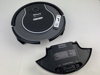
Push down on the black tab and remove the dust bin
In the first image, the device looks significantly different for Step 13 to Step 14, then the device is flipped in the second and third images. Be careful about these kinds of continuity errors.
-
-
-
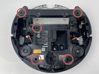
Using a Torx TR15 screwdriver, remove the five screws from the bottom cover.
Use markup on images to show where components are. Past Step 15, here, I’m no longer marking this issue. Additionally, proofread all steps for end punctuation.
-
-
-
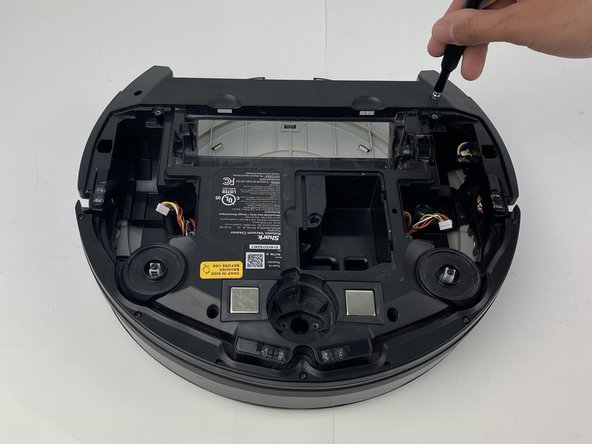
Using a Torx TR15 screwdriver, remove the five screws along the front edge of the device.
-
Pull the bottom part of the bump guard away from the body of the device.
What does it mean to face the device rearward?
Do you have pictures of you removing the bump guard?
-
-
-
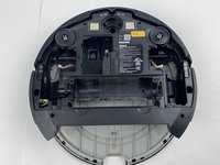
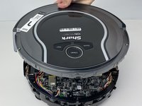
Lift the top cover up from the rear of the robot to separate the top cover from the rest of the robot.
What is the difference between the two black bullets? Also, the information bullet is not necessary here.
-
-
-
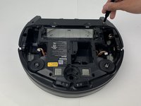
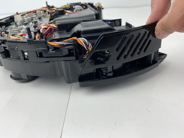
Using a Phillips #00 screwdriver, remove the screw holding down the diagonally vented side cover.
-
Slide the sensor out from the base of the robot
-
-
-
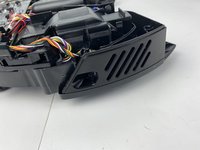
Lift up the diagonally vented cover on the side of the robot containing the side sensor.
-
-
-
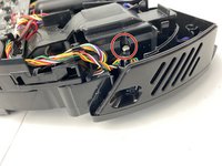
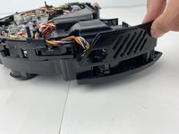
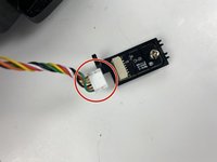
Disconnect the white connector from the sensor.
-
-
-
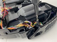
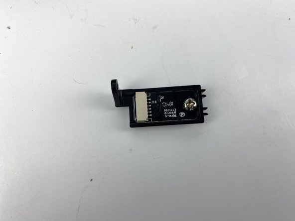
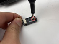
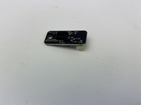
Using a Phillips #00 screwdriver, remove the screw on the sensor.
-
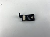
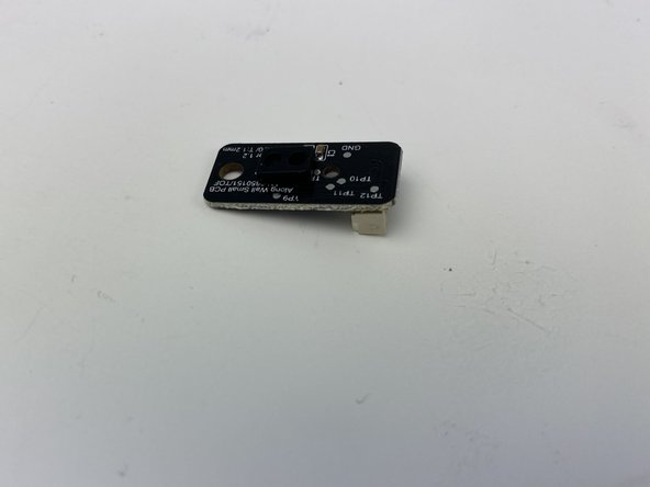
Remove the sensor from its mount.
Do you have a picture of you separating the components? Also, make sure to write directions as commands.
where can I buy the sensor
And thats why i bought this robot because i don't have a man, funny i paid $300 after one year i have to work on it?? I have different Shark products and this is the first im not happy with Shark.
Yes, I agree. We have only had it less than a year and we are having problems with it already. What a joke.
Less than year and I’m
Having this issue as well very disappointing. It doesn’t say where to get the sensor .
-


To reassemble your device, follow these instructions in reverse order.
To reassemble your device, follow these instructions in reverse order.
crwdns2935221:0crwdne2935221:0
crwdns2935227:0crwdne2935227:0
crwdns2915084:0crwdne2915084:0

Embry-Riddle Aeronautical University, Team S3-G6, Watkins Spring 2020 crwdns2935289:0Embry-Riddle Aeronautical University, Team S3-G6, Watkins Spring 2020crwdne2935289:0
ERAU-WATKINS-S20S3G6
crwdns2931471:04crwdne2931471:0
crwdns2935297:014crwdne2935297:0
crwdns2947410:01crwdne2947410:0
Curious if anyone ever saw the WiFi die in these? I cannot get the shark WiFi to show so I can add it to the network. I press both the bottoms and the icon flashes but shark WiFi never shows so the app can continue.
Here, you have misused the reminder bullet. The note bullet would be better in this case; I would also say how to turn it off, rather than just to do it. Avoid locate steps, and instead, move straight to the information about what to do. Use markup on the images to indicate where the component is. Be careful about using “remove” without other information about how to remove it, especially if there are multiple ways to remove something.
Alex Watkins - crwdns2934203:0crwdne2934203:0