crwdns2915892:0crwdne2915892:0
A guide to remove the Logic Board from the Sega Dreamcast.
crwdns2942213:0crwdne2942213:0
-
-
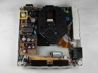
Flip the console over on its back.
-
Take note of your model number, in case replacement parts are needed.
-
-
-
Remove the expansion bay by applying pressure to the small clip on the expansion bay while prying it away from the console.
-
-
-
Locate and remove all four black 12mm Phillips #02 screws from the underside of the console.
-
-
-
Turn the console right side up.
-
Remove the top cover by gently lifting the upper portion of the console.
-
-
-
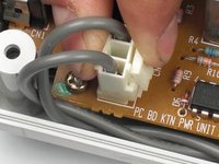
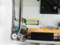
Remove the white female pin header by clamping the clip and pulling it up gently from the power board.
-
-
-
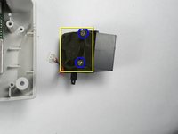
Remove the two 10mm Philips #02 screws that are fastened to the power block.
-
-
-
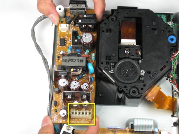
Do not bend the male pin header between the mounted head when you remove the power supply from the chassis.
-
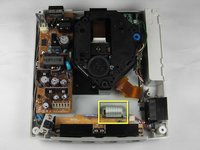
Remove the power board by using both hands to gently lift the power board away from the console.
-
-
-
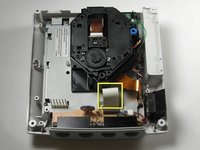
Remove the clear plastic film that is tucked between the power supply and the chassis.
-
-
-
-
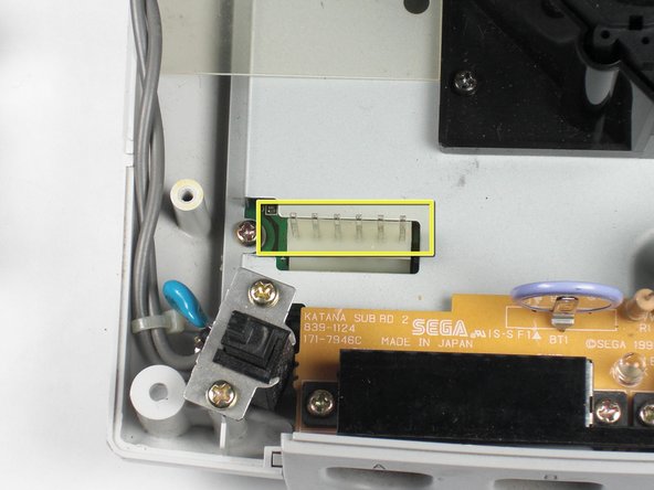
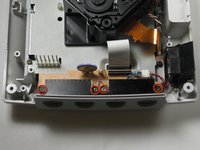
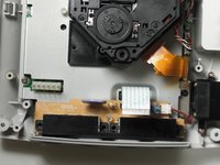
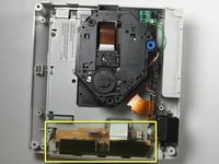
Disconnect the white controller cable by gently pulling the the cable while wiggling it back and forth until it detaches from the controller board.
Note that on some Dreamcasts the power board (on the left) overhangs slightly over the controller board, meaning one must also remove the power board at this stage. This is relatively straightforward, fortunately. Remove a screw each at the top left of the power board and at the bottom left of the power board, remove the white clip at the top left, pop out the white clip on the left of the power board and lift the power board out from the front where you have the white block containing eight pins that connect the power board to the sub board. Then proceed per the rest of this guide. Hope this helps.
-
-
-
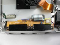
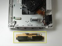
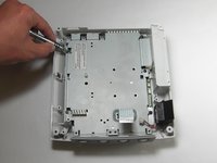
Remove the four 14mm Philips #02 screws located on the controller board.
-
-
-
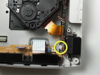
Disconnect the white fan header from the controller port.
Perhaps list the battery type an battery holders that allow for easy replacement in the future?
-
-
-
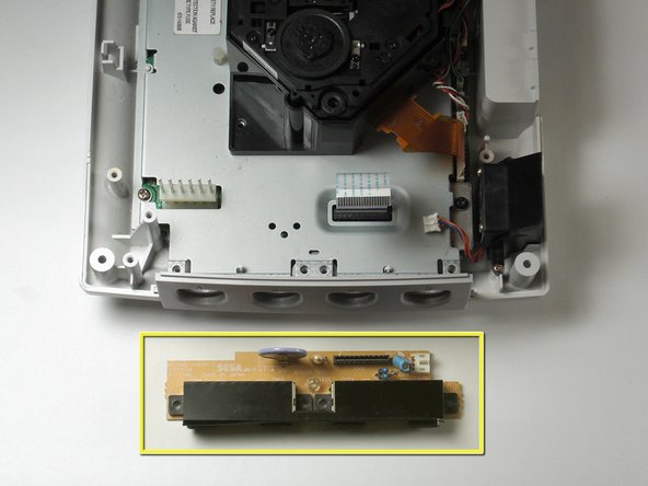
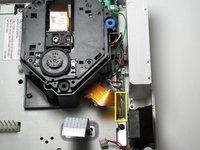
Remove the controller board by lifting it up from the controller port.
-
-
-
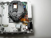
Detach the orange cable by giving it a gentle pull while wiggling the cable back and forth until it loosens from the logic board.
-
-
-
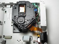
Detach the cables by gently pulling the three GD-ROM cables to remove them from the logic board.
-
-
-
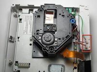
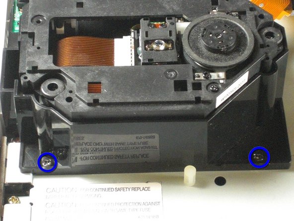
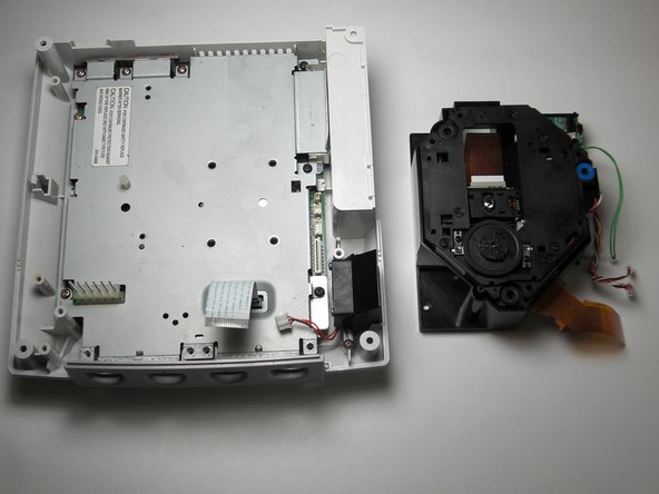
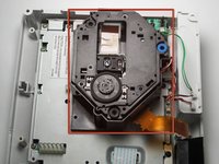
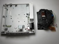
Remove the two black 12mm Philips #02 screws located on the left side of the GD-ROM bracket.
-
-
-
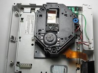
Remove the GD-ROM by gently lifting it from its base.
-
-
-
Remove the white fan header by gently pulling it away from from the controller port.
-
-
-
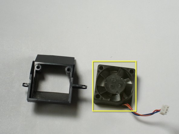
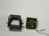
Remove the two 8.5mm Philips #00 screws from the fan bracket.
-
-
-
Remove the two 17.5mm Philips #00 screws from the fan bracket.
-
Remove the fan from the bracket.
-
-
-
Remove the five 10mm Philips #02 screws from left side of the logic board cover.
-
Remove the three black 12mm Philips #02 screws from the right side of the logic board cover.
-
-
-
Lift the metal cover from the console.
-
-
-
Remove the logic board and set the logic board on an anti-static surface.
-


To reassemble your device, follow these instructions in reverse order.
To reassemble your device, follow these instructions in reverse order.
crwdns2935221:0crwdne2935221:0
crwdns2935229:023crwdne2935229:0
crwdns2915084:0crwdne2915084:0

Cal Poly, Team 5-1, Regan Fall 2009 crwdns2935289:0Cal Poly, Team 5-1, Regan Fall 2009crwdne2935289:0
CPSU-REGAN-F09S5G1
crwdns2931471:05crwdne2931471:0
crwdns2935297:021crwdne2935297:0
crwdns2947410:01crwdne2947410:0
helpful but my dreamcast had a different logic board and as well as fan and gd-rom so keep that in mind if u see something different in your unit