crwdns2915892:0crwdne2915892:0
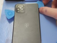
Use this guide to replace the screen on your Revvl 6 Pro 5G.
It should be noted that the screen used in this guide is very similar to the Revvl 6, Revvl 6 5G, and Revvl 6 Pro, in addition to the Revvl 6 Pro 5G. All the photos used in this guide are with the Revvl 6 Pro 5G, but the process is likely similar on these other models.
crwdns2942213:0crwdne2942213:0
-
-
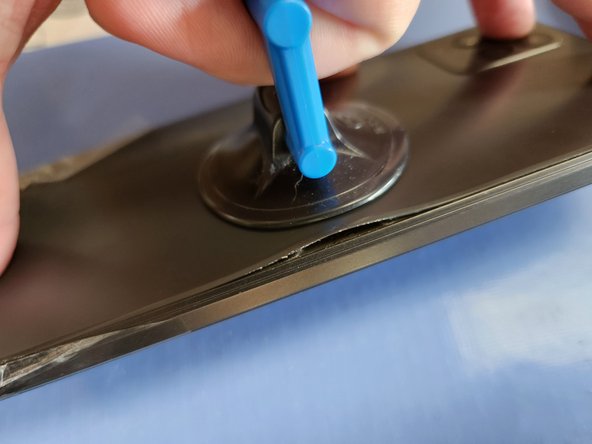
Before working on this device, prepare to heat it up to soften the adhesive. You can use a heat mat (in this guide's photos), but you can also use a hair dryer, heat gun, iOpener, or whatever method you have available.
-
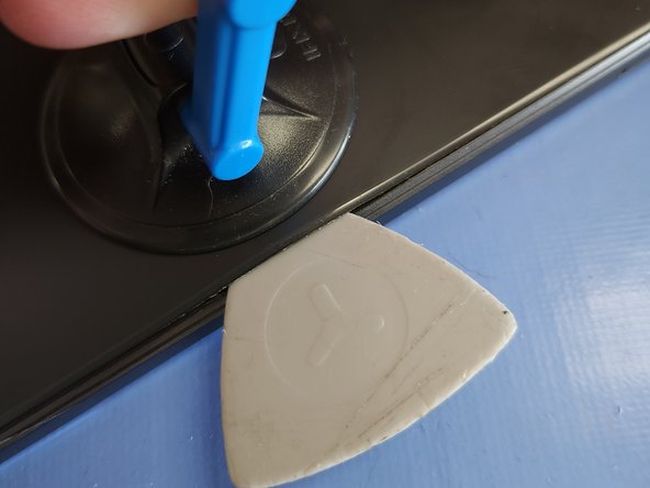
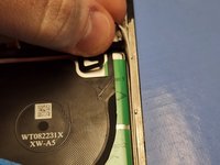
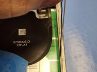
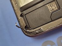
Once the back is properly heated, apply your Suction Cup to the right side. Pull up hard to break the seal and allow a gap for your Opening Pick to slide in.
-
After your Opening Pick is in, you can remove the Suction Cup.
-
-
-
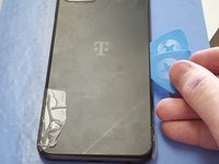
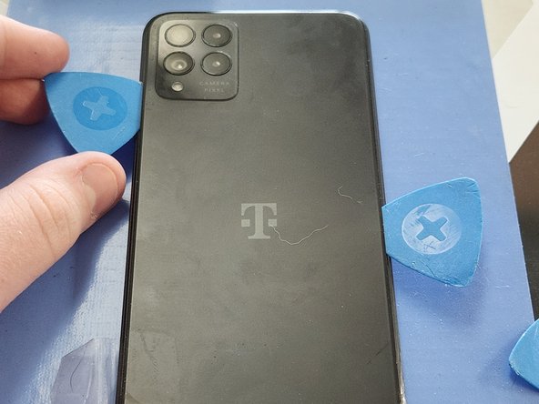
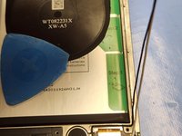
Leaving your first Opening Pick where it is to prevent the adhesive from resealing, slide a second on into the gap, and down around the bottom corners.
-
-
-
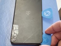
Continue sliding that same Opening Pick up the left side, but stop when you get to the camera.
-
-
-
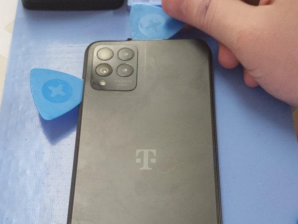
Going back to the original Opening Pick, slide it up the right side and around the top corner.
-
Once again, stop once you get to the camera.
-
-
-
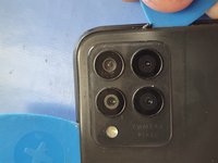
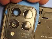
When at the camera, tilt your Opening Pick upwards.
-
Slide your Opening Pick under the back of the phone but over the camera glass.
-
You may need to go all the way around the cameras, as there is a separate strip of adhesive around the cameras specifically.
-
-
-
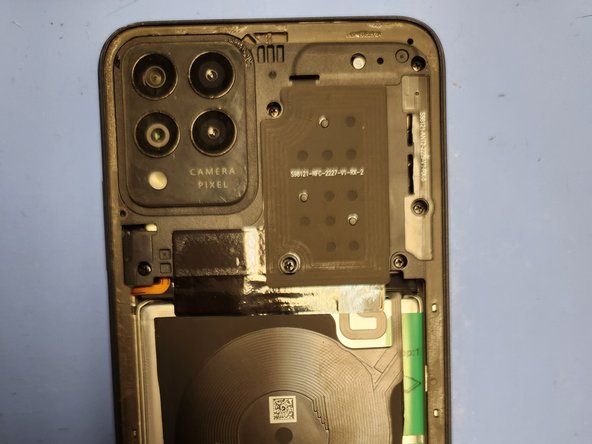
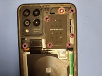
Remove the 7 Screws holding the midframe in over the motherboard.
-
One of these screws has an "S" tamper evident seal. Don't miss it!
-
-
-
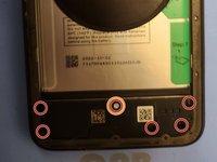
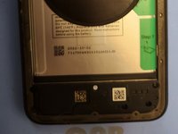
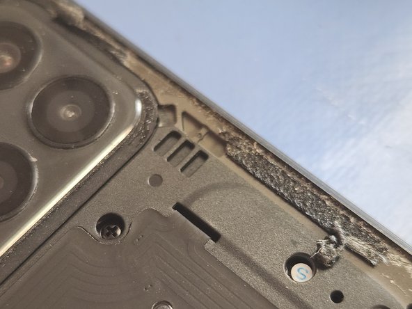
Remove the 6 screws holding the midframe in over the daughterboard.
-
One of these screws has an "S" tamper evident seal. Don't miss it!
-
-
-
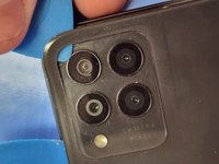
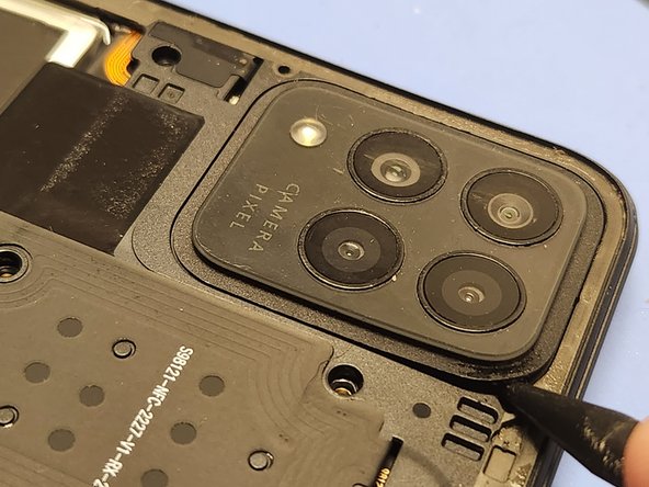
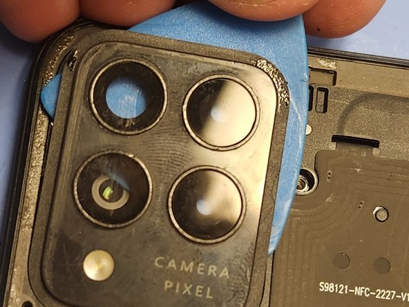
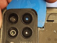
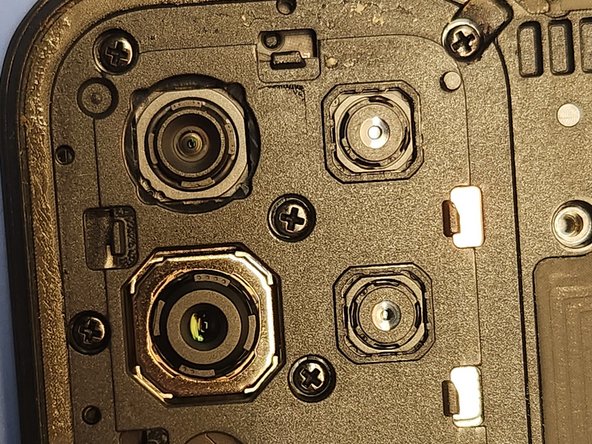
Insert the tip of your Spudger into the small gap at the corner of the camera lens.
-
Lift up and create a gap under the lens.
-
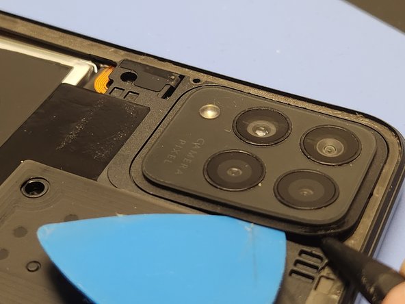
Insert an Opening Pick into the gap created by your Spudger.
-
-
-
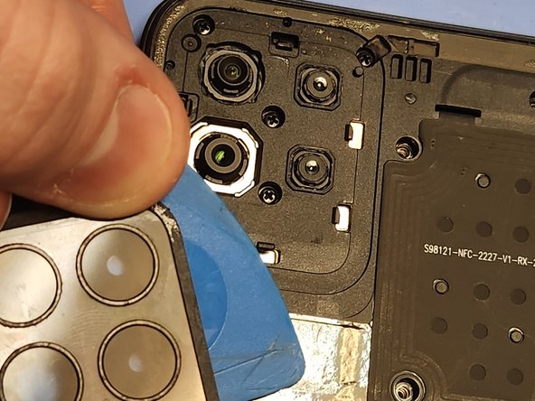
With your Opening Pick inserted, leverage the camera lens up and off.
-
The camera lens is held in place by both adhesive and clips, and may make two snapping sounds when being removed.
-
-
-
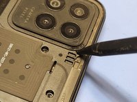
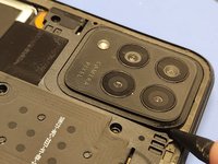
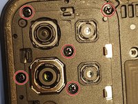
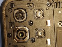
Remove the 5 screws holding the midframe in over the cameras.
-
-
-
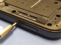
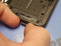
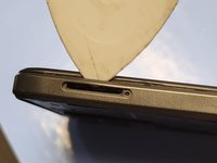
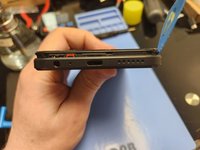
Using your Sim Card Ejection Tool, or just a paperclip, insert it into the hole of the sim card tray.
-
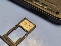
Pull out the sim card tray.
-
-
-
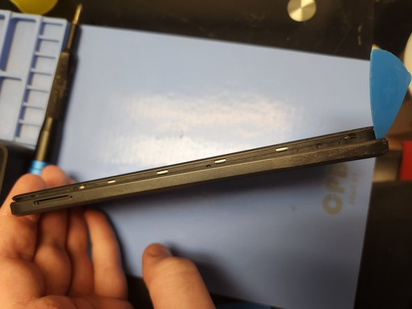
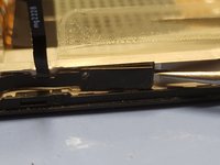
Insert an Opening Pick into the gap between the midframe and the screen frame where the sim card tray was.
-
The plastic is thinnest in this area and flexible, so you should be able to force your Opening Pick into the seam.
-
Move your Opening Pick down the right side of the phone and around the bottom corners.
-
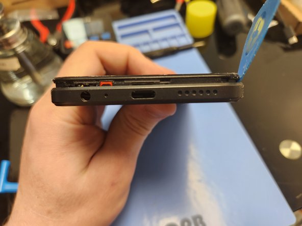
On the left side, only move the Opening Pick up halfway, and stop before reaching the power button.
-
Go back to the right side and move your Opening Pick over the top, but stop after the top left corner before getting to the buttons.
-
-
-
-
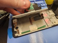
Once the clips are released, lay the phone back down on its screen and gently lift the midframe up.
-
Open it as you would a book, making sure to treat it like a hinge on the left side, as the power button is still attached by a delicate ribbon cable.
-
Turn the midframe over and lie it down flipped over next to the phone.
-
-
-
With the midframe beside the phone, use an Opening Pick or Spudger to disconnect the power button from the motherboard.
-
-
-
Use an Opening Pick or Spudger to disconnect the battery from the motherboard.
-
-
-
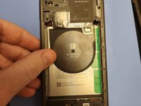
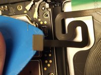
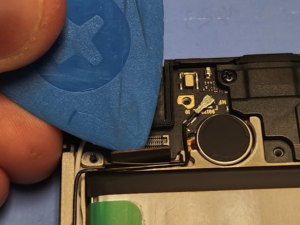
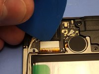
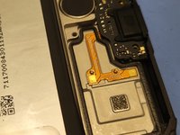
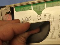
Use an Opening Pick or Spudger to disconnect the wireless charging coil from the motherboard.
-
-
-
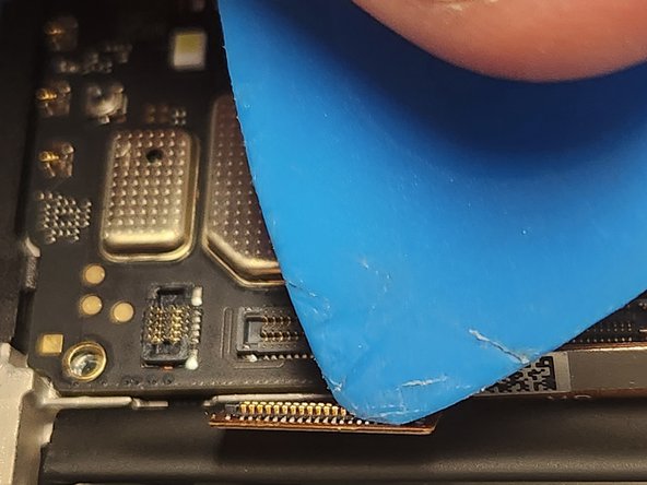
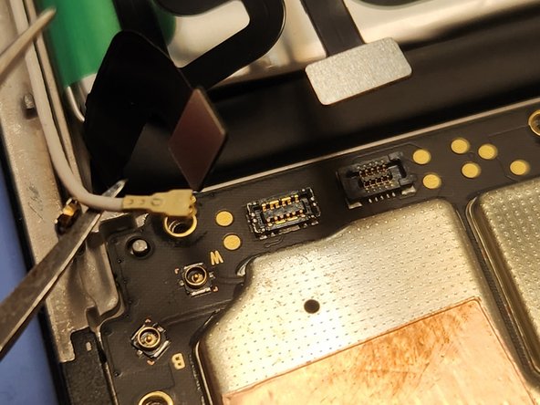
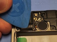
Use an Opening Pick or Spudger to disconnect the two screen connectors from the motherboard.
-
-
-
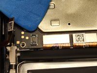
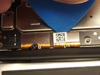
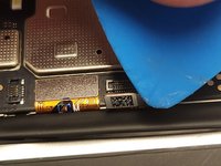
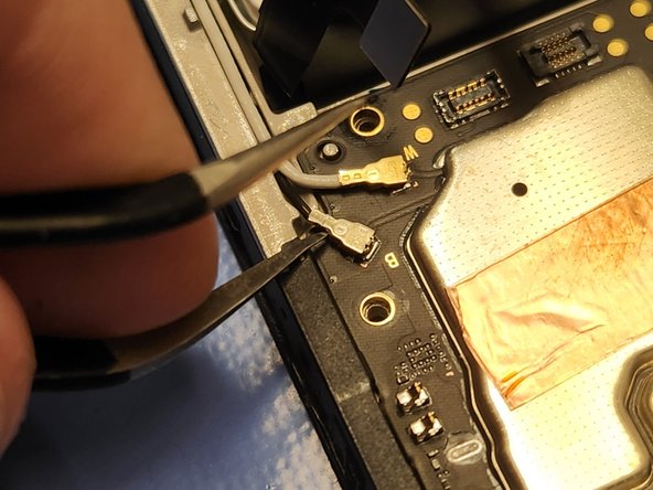
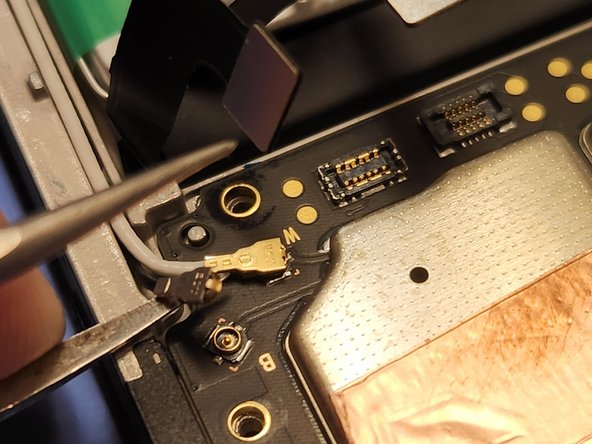
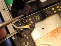
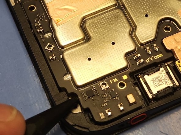
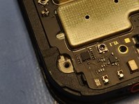
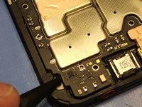
Use your Tweezers to disconnect the two Antennas from the motherboard.
-
-
-
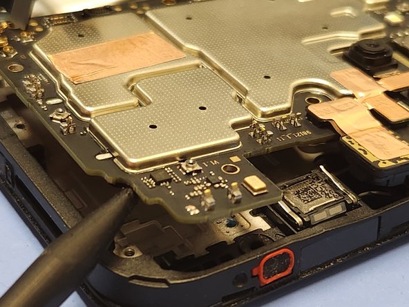
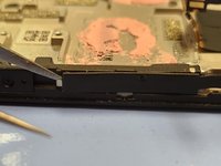
There is a small gap in the top right corner of the phone, giving you access between the motherboard and the frame.
-
Insert your Spudger into this gap, and gently pry upwards. The motherboard should now lift freely away from the frame of the screen.
-
-
-
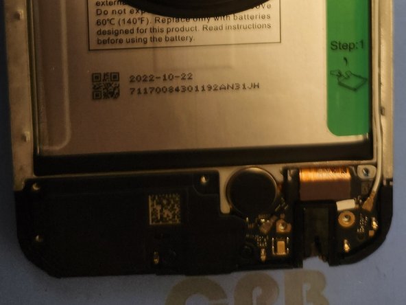
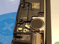
Remove the 2 screws holding the loudspeaker in over the daughterboard.
-
-
-
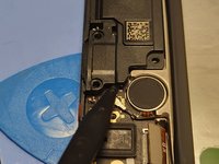
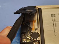
There is a small gap on the far right side of the loudspeaker, giving you access between the speaker and the daughterboard.
-
Insert your Spudger into this hole, and gently pry upwards. The loudspeaker should now lift freely away from the frame of the daughterboard.
-
-
-
Use an Opening Pick or Spudger to disconnect the screen from the daughterboard.
-
-
-
With the motherboard removed, gently lift up on the antenna to remove it from the channel on the side of the frame.
-
-
-
There is a small gap in the top left corner of the daughterboard, giving you access between the daughterboard and the frame.
-
Insert your Spudger into this gap, and gently pry upwards. The daughterboard should now lift freely away from the frame of the screen.
-
-
-
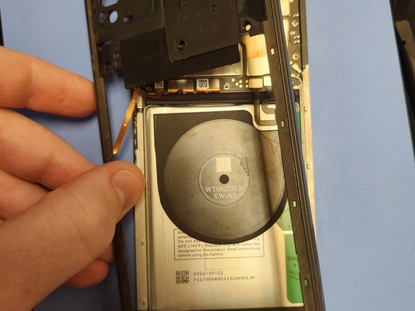
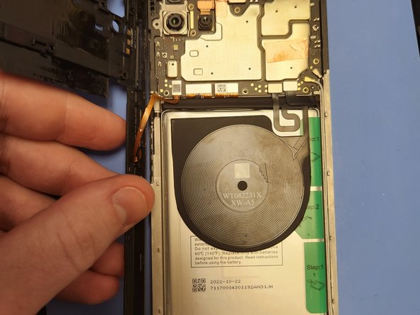
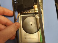
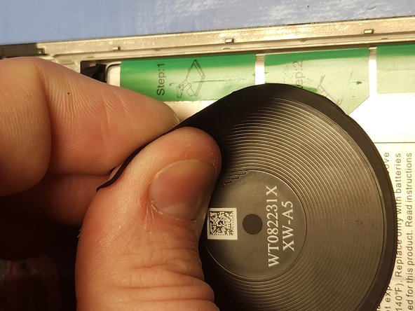
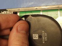
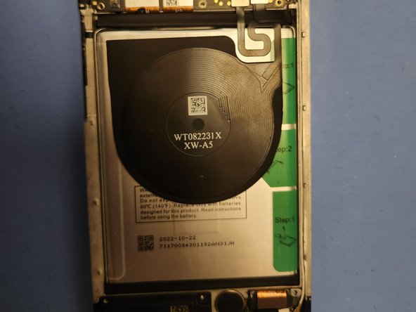
Carefully peel back the wireless charging coil from the right side of the battery to reveal the tabs underneath.
-
-
-
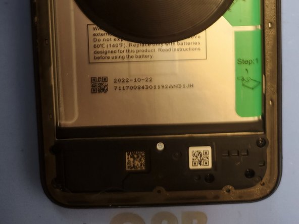
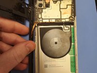
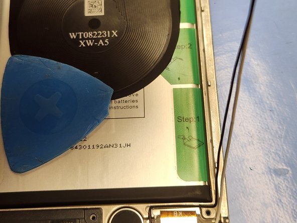
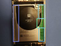
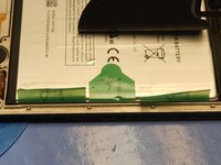
There are two tabs on the right side of the battery marked "Step 1". These tabs are attached to the frame of the phone and should not be pulled on. They only need to be peeled away from the battery.
-
There is a large tab on the left side of the battery. This is unmarked, but should be carefully removed, as not doing so can damage the wireless charging coil if still attached.
-
There is one tab on the right side of the battery marked "Step 2". After the other tabs are peeled off the battery, this one is pulled on to remove the battery from the phone.
-
-
-
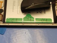
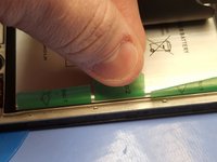
With the wireless charging coil out of the way, gently peel both tabs labelled "Step 1" off of the battery.
-
-
-
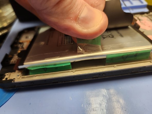
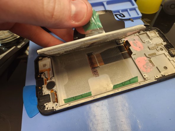
With the wireless charging coil and all tabs peeled back, pull up forcefully on Tab 2 to pull the battery off of the frame.
-
It is more important to give consistant pulling force rather than short sharp pulls on the tab.
-
If at any time it is too difficult to pull the battery up, stop and apply heat to the screen side of the device to soften the adhesive.
-
-
-
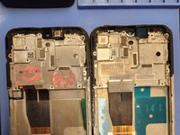
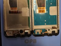
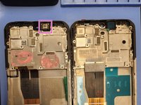
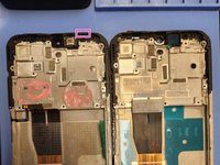
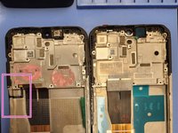
With all major components removed, place your old screen and new screen side by side and transfer over any small parts that may be left behind.
-
-
-
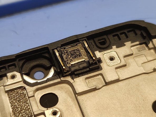
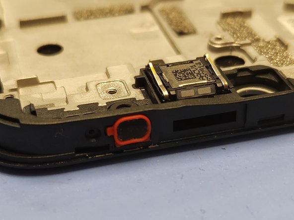
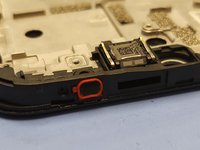
The earpiece speaker is located here.
-
The earpiece speaker is successfully transferred to the new screen and frame.
-
-
-
The top microphone filter is located here (top edge of frame).
-
The top microphone filter is successfully transferred to the new screen and frame.
-
-
-
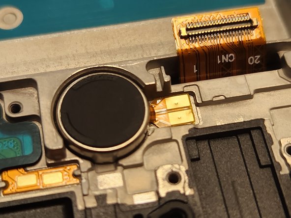
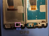
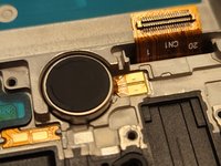
The vibration motor is located here.
-
The bottom microphone filter is located here (bottom edge of frame).
-
The both parts are successfully transferred to the new screen and frame.
-
-
-
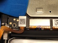
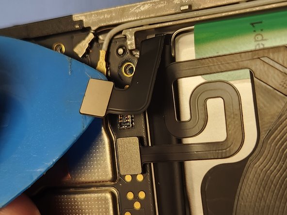
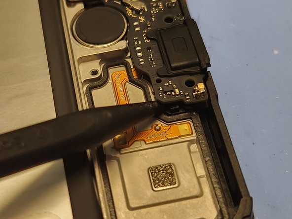
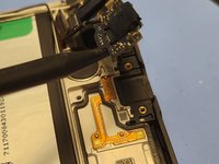
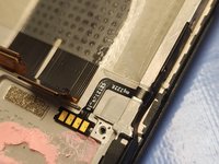
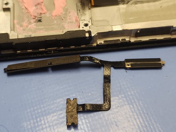
The side buttons are located here, on a small and delicate ribbon cable that wraps around from the left side of the frame to the inside, under the motherboard.
-
Insert the tip of your tweezers under the contact pads. There is a small gap that is hard to see that will let you get your tweezers under the contact pads to provide some leverage.
-
Once the contact pads are lifted up, gently pull the ribbon cable up with your fingers to release it from the adhesive holding it to the frame.
-
-
-
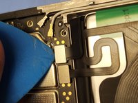
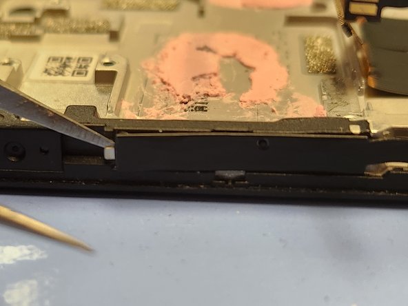
Insert your tweezers into the small opening to the right of the ribbon cable and peel up the right side.
-
Insert your tweezers into the small opening to the left of the ribbon cable and peel up the left side.
-
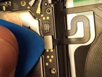
Once both sides are peeled up, gently pull the ribbon cable up with your fingers to release it from the adhesive holding it to the frame.
-
With both sides and the contact pads released, you should be able to pull the ribbon cable away from the frame of the phone with no further issues.
-
After fully removing the side buttons ribbon cable, install it onto the new screen and frame.
-
-
-
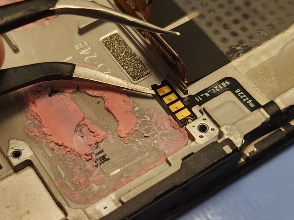
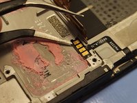
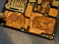
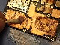
Use 90%+ isopropyl alcohol on a Q-Tip, or the nearest equivalent available to you, to clean the old thermal paste off of the motherboard.
-
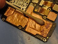
Apply new thermal paste or thermal pads to the area that was previously covered with thermal paste before installing the motherboard into the new frame.
-
-
-
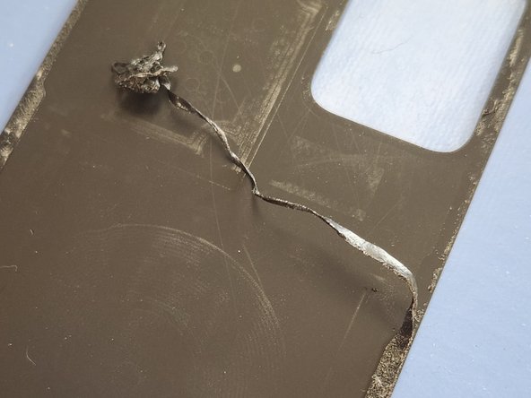
When reassembling the phone, inspect the midframe and rear cover for any old adhesive seal. Make sure to completely remove any traces of it left behind.
-
Use 90%+ isopropyl alcohol on a Q-Tip, or the nearest equivalent available to you, to clean the adhesive residue off of the midframe and back cover.
-
Apply new Tesa tape or your adhesive of choice to the border of the midframe and border around the camera lens before installing the back cover onto the phone.
-


To reassemble your device, follow these instructions in reverse order. The camera lens will need to snap into place, and takes more force to put back than you may be expecting. Pay extra care to make sure you cleaned the old seal off properly.
To reassemble your device, follow these instructions in reverse order. The camera lens will need to snap into place, and takes more force to put back than you may be expecting. Pay extra care to make sure you cleaned the old seal off properly.
crwdns2935221:0crwdne2935221:0
crwdns2935229:03crwdne2935229:0

crwdns2915084:0crwdne2915084:0

Eagle River Electronics crwdns2935289:0Eagle River Electronicscrwdne2935289:0
Business
crwdns2934841:01crwdne2934841:0
crwdns2935297:019crwdne2935297:0
crwdns2947412:04crwdne2947412:0
Hey is there anyone who has had a problem with the phone not turning back on after the screen replacement? If so how did you fix it?
Did not experience anything like that during my repair. I would double check, in no particular order, that the battery is properly connected, the power button is properly connected, and that the screen ordered was from a reputable supplier and is for the exact correct model phone. You can also try reassembling with the old (presumably broken) screen and seeing if the phone powers on. If everything is double and triple checked and it does not power on with either the new or old screen, then it is likely damaged motherboard, or potentially other critical component for power. If it powers on with the old screen but not the new one, it is likely an incorrect screen ordered or delivered by mistake, or even a faulty product.
Has anyone had an issue with it not charging after a screen repair? My screen is repaired and working great but now my charging port isn't working with my phone at all? Any help please I don't have any other options and no money to get a replacement for the phone and it's my lifeline. Please let me know ASAP thanks!
Hello Adina.
The charging port is connected through an interconnect cable built into the screen/midframe. I would recommend you double check the connection from step 23 on the charging port side, as well as the two connectors step 18.
It's important to note that all of the bottom connections are passed through this same cable. Things like the bottom speaker and your microphones and your vibration motor. If this connection isn't secure, then none of these functions should work. If those other functions DO work, then you may have damaged the USB-C port or some of the circuitry such as accidentally knocking off an SMD cap or such. If this has happened, the only solution would be to replace the charging port board itself.
Sorry I can't exactly answer your question but it's most likely one of those two possibilities. Hope this helps!