crwdns2915892:0crwdne2915892:0
Trip over your power cord? Use this guide to replace your DC-in board.
crwdns2942213:0crwdne2942213:0
-
-
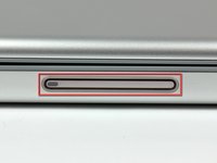
Use your thumbs to push the two battery retaining tabs away from the battery.
-
The battery should pop up enough to rotate it toward yourself and lift it out of the lower case.
-
-
-
Remove the three 2.3 mm Phillips screws securing the memory cover to the lower case.
-
-
-
Lift the memory cover slightly and pull it toward yourself to remove it from the lower case.
-
-
-
Remove the following ten screws:
-
Two 14.7 mm shouldered Phillips.
-
Three 12.3 mm Phillips.
-
One 3.8 mm T8 Torx.
-
One 6.8 mm T8 Torx.
-
Three 1.3 mm Phillips.
-
-
-
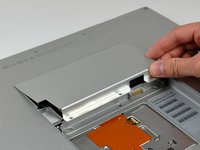
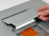
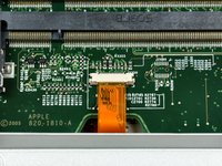
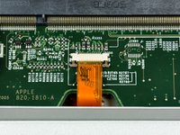
Use your fingernails to separate the ZIF cable lock away from its socket. (Move the two brown bits down 1mm)
-
-
-
Use the tip of a spudger to slide the trackpad ribbon cable out of its socket.
-
-
-
Remove the four 3.4 mm Phillips screws from the PC card side of the PowerBook.
-
-
-
-
Remove the four 3.4 mm Phillips screws from the DVI connector side of the PowerBook.
-
-
-
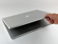
Depress the display latch release button and open your display.
-
-
-
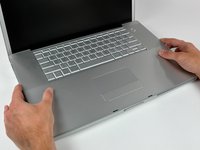
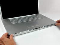
Starting near the display, lift the upper case straight up off the lower case, minding any cables that may get caught.
-
-
-
Remove the strip of tape covering the speaker cables.
-
-
-
Disconnect the RJ-11 cable from the modem.
-
-
-
Use your fingernails or the tip of a spudger to separate the ZIF cable lock from its socket.
-
-
-
Pull the DC-in cable out of its socket.
-
-
-
Peel the DC-in cable off the adhesive securing it to the lower case.
-
-
-
Use the tip of a spudger to remove the piece of foam tape from the channel on the side of the left speaker.
-
De-route the cables from the channel in the left speaker.
-
-
-
Remove the single T8 Torx screw securing the left speaker to the lower case.
-
Lift the left speaker from its rear edge and maneuver it out of the lower case, minding the cables sitting in the channel near the front edge of the left speaker.
-
Set the speaker next to the lower case.
-
-
-
Pull the DC power cable connector straight up off the DC-in board.
-
-
-
Remove the two T8 Torx screws securing the DC-in board to the lower case.
-
New line.
-
-
-
Pull the DC-in board away from the side of the lower case to separate the ports from their bezel.
-
Lift the DC-in board out of the lower case.
-


To reassemble your device, follow these instructions in reverse order.
To reassemble your device, follow these instructions in reverse order.
