crwdns2915892:0crwdne2915892:0
Follow this guide to remove and replace the laser on a PlayStation 5.
Before you begin, completely power down and unplug all cables from your console. Remember to follow general electrostatic discharge (ESD) safety procedures while repairing the console.
crwdns2942213:0crwdne2942213:0
-
-
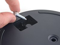
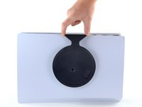
If your PlayStation 5 is in its vertical orientation, flip it upside down so the stand is facing up.
-
Use a coin or a flathead screwdriver to remove the 26.5 mm-long stand screw.
-
-
-
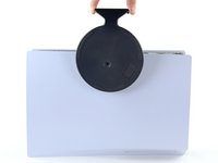
Lift straight up to remove the stand.
-
-
-
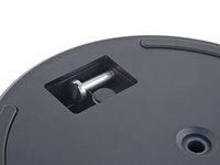
Insert the screw into the cubby on the bottom of the stand.
-
-
crwdns2935267:0crwdne2935267:0Tweezers$4.99
-
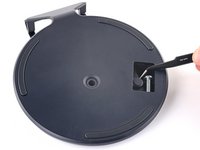
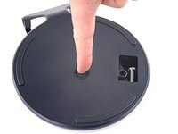
Use a pair of tweezers or your fingernail to remove the cap from the cubby.
-
Use your finger to press the cap into the screw hole.
-
-
-
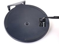
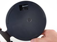
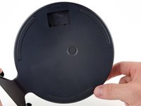
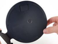
Twist the stand counterclockwise to close the cubby.
-
-
-
If your PlayStation 5 is in its horizontal orientation, rest it on its face with the charging port facing up.
-
Lift the stand straight up to remove it.
-
-
-
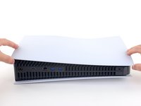
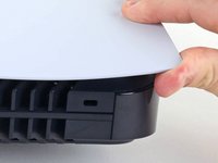
Flip the device over so that the USB and ethernet ports are on the left side from your perspective.
-
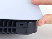
Lift up the corner of the faceplate to unclip it from the case.
-
-
-
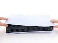
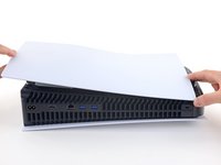
While lifting up the corner, slide the faceplate towards the bottom of the device.
-
Remove the right faceplate.
-
-
-
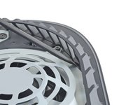
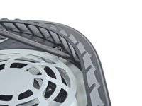
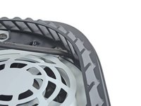
Insert the flat end of a spudger underneath the grille and into the gap above the fan.
-
Lift up with the spudger to pry the grille away from the case.
-
-
-
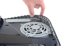
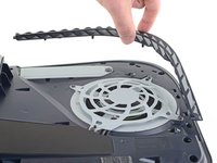
Lift the grille away from the case to remove it.
-
-
crwdns2935267:0crwdne2935267:0Magnetic Project Mat$19.95
-
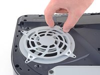
Use a T9 Torx Security driver to remove the four screws securing the fan shroud to the case:
-
Two 23.3 mm-long screws
-
One 11.4 mm-long screw
-
One 31 mm-long screw
-
-
-
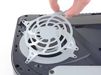
Lift the fan shroud straight up to remove it.
-
-
-
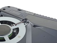
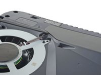
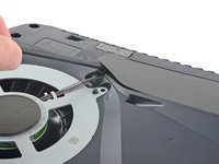
Insert the flat end of a spudger beneath the black wire cover and into the gap above the fan wires.
-
Use the spudger to peel up the wire cover until you can grip it with your fingers.
-
-
-
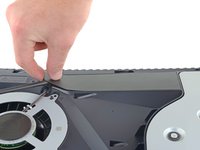
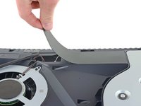
Use your fingers to peel off the wire cover.
-
-
-
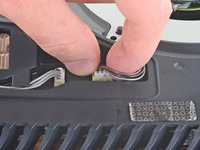
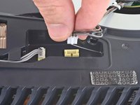
Use your fingers to grip the edges of the fan cable connector, and pull up to disconnect it from the motherboard.
-
-
-
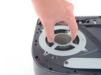
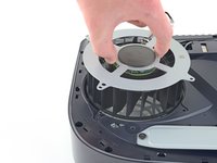
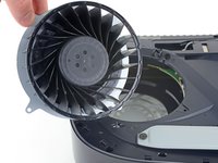
Lift the fan up and out of the case to remove it.
-
-
-
-
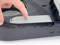
Use a Phillips screwdriver to remove the 17 mm-long SSD cover screw.
-
-
-
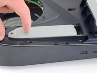
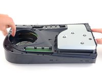
Use your finger to slide the SSD cover towards the top of the device to unclip it from the case.
-
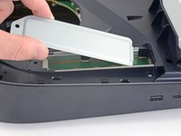
Remove the SSD cover.
-
-
-
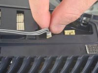
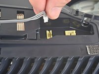
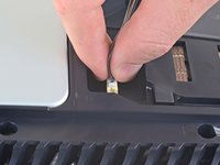
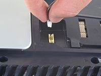
Use your fingers to grip the edges of the optical drive cable connector, and pull up to disconnect it from the motherboard.
-
-
-
Use your fingers to grip the edges of the optical drive cable connector, and pull up to disconnect it from the optical drive.
-
-
crwdns2935267:0crwdne2935267:0Tweezers$4.99
-
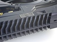
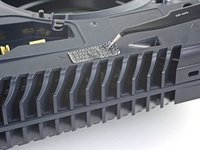
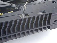
Use a pair of tweezers to remove the tamper-evident sticker covering the remaining case screw.
-
-
-
Use a T8 Torx driver to remove the eleven screws securing the case:
-
Six 18.6 mm-long screws
-
Two 23.3 mm-long screws
-
Two 43.2 mm-long screws
-
One 7.3 mm-long screw
-
-
-
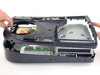
Lift the case straight up to remove it.
-
-
-
Use the flat end of a spudger to press down on the optical drive connector's metal locking tab.
-
With the metal tab depressed, use a pair of tweezers to pull the blue pull tab directly away from the connector to disconnect the cable from the optical drive.
-
-
-
Lift the optical drive away from the device to remove it.
-
-
-
silver screws: 4x M1.6 X 3.7mm, with 6.5mm head.
-
black screws: 9x M1.6 x 3.8mm.
-
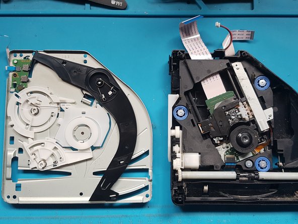
Remove screws with Phillips #1 screwdriver.
-
-
-
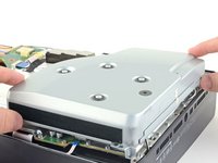
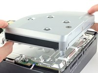
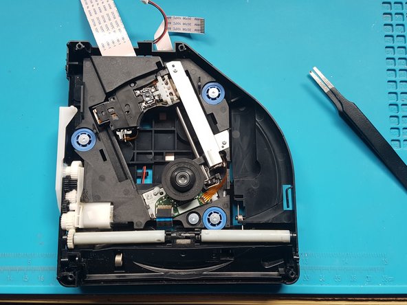
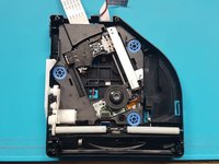
Lift off the top cover.
-
-
crwdns2935267:0crwdne2935267:0Tweezers$4.99
-
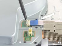
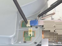
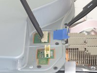
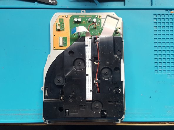
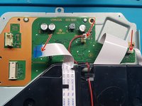
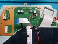
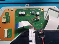
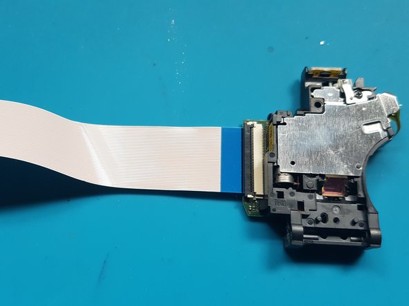
Gently pull the medium and narrow FFC flexes and the 2-wire lead from their sockets. Suitable tweezers (bent with points or straight blunt end) can be used to aid removal.
-
-
-
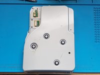
Remove screws with Phillips #1 screwdriver.
-
black screws: 2x M1.6 x 3.8mm
-
-
-
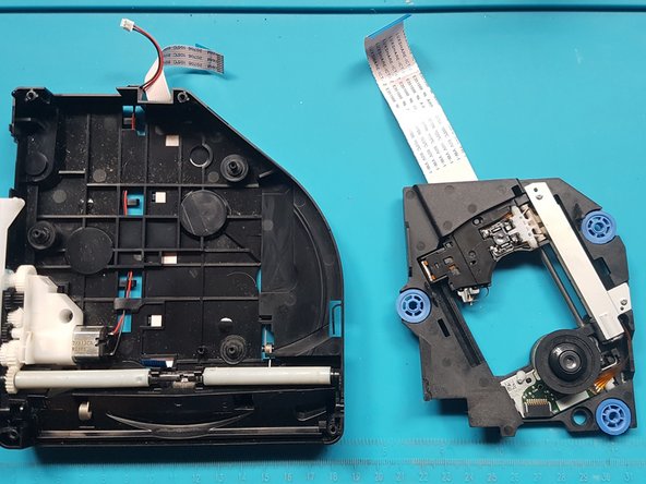
Lift off the PCB and attached assembly from the metal plate.
-
-
-
Turn over the PCB and attached assembly.
-
-
-
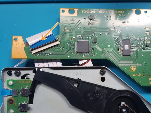
Unlatch the wide FFC socket.
-
Gently remove the wide FFC cable from the socket and set aside the PCB.
-
-
-
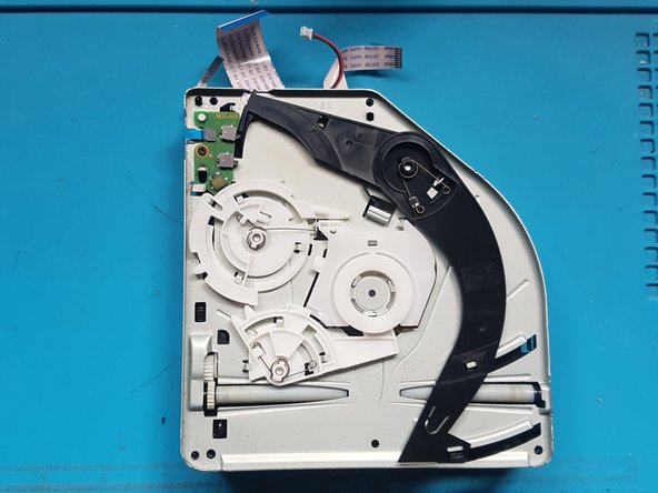
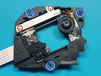
Flip over the assembly.
-
-
-
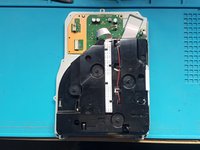
Use a Phillips #1 screwdriver to remove the screws.
-
black screws: 4x M1.6 x 3.8mm.
-
-
-
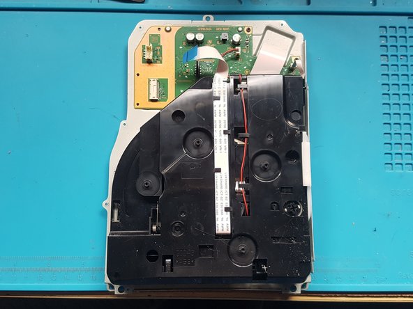
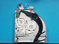
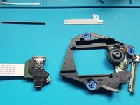
Remove the mechanism plate and set aside.
-
-
-
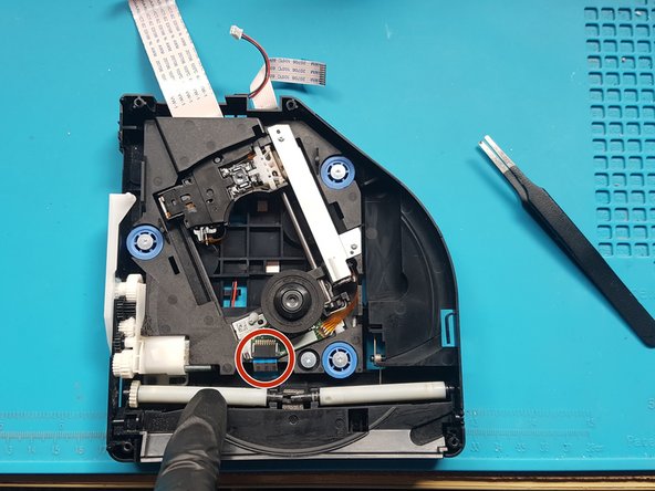
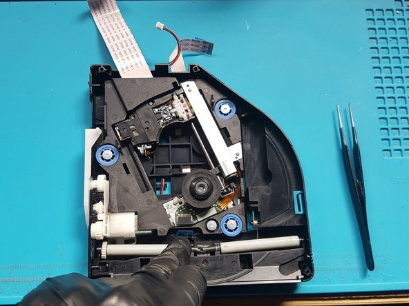
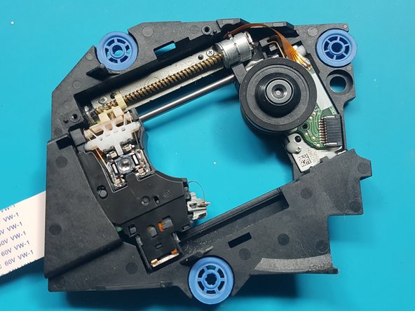
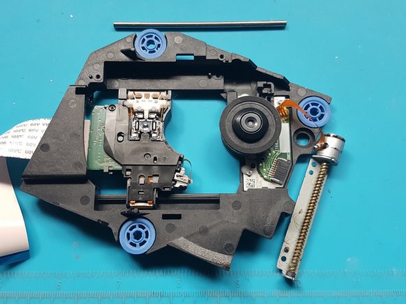
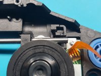
Push down on the roller mech and remove the FFC cable from laser deck (near roller mech).
-
-
-
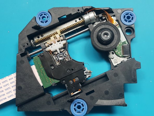
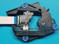
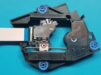
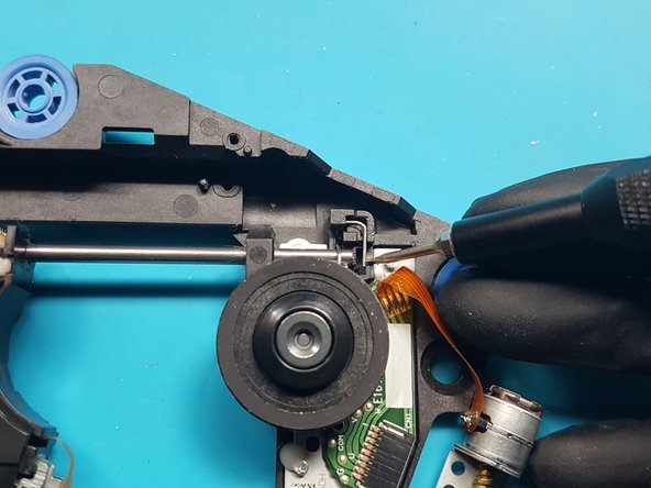
silver screws: 4x M1.6 X 3.7mm 6.5mm head
-
-
-
silver screws: 2x M1.7 X 3.8mm
-
-
-
silver screws: 2x M1.7 X 3.8mm
-
-
-
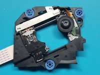
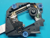
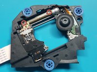
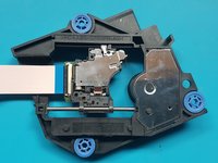
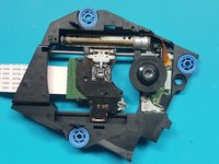
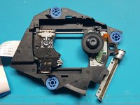
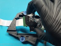
Flip over the laser module.
-
-
-
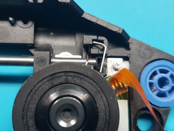
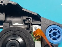
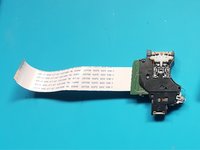
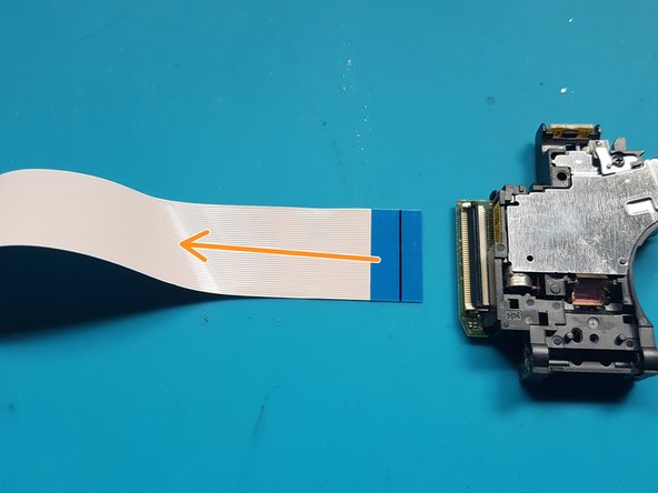
unlatch the FFC connector.
-
Remove the FFC flex from the laser.
-


To reassemble your device, follow these instructions in reverse order.
Take your e-waste to an R2 or e-Stewards certified recycler.
Repair didn’t go as planned? Try some basic troubleshooting, or ask our PlayStation 5 Answers community for help.
To reassemble your device, follow these instructions in reverse order.
Take your e-waste to an R2 or e-Stewards certified recycler.
Repair didn’t go as planned? Try some basic troubleshooting, or ask our PlayStation 5 Answers community for help.
crwdns2935221:0crwdne2935221:0
crwdns2935229:015crwdne2935229:0

crwdns2947412:04crwdne2947412:0
Danke für die tolle und ausführliche Anleitung!
Discs werden wieder gelesen *freu*
where do we get the replacement laser?
Muchísimas gracias por la guía, me ha resultado imprescindible para hacer el cambio con éxito!
whats the name of the ribbon data cable that goes from this drive to the ps. The one taken off at the start before tearing down the bluray playe. Thanks