crwdns2915892:0crwdne2915892:0
Follow the procedure outlined in this guide to remove and install the circuit board for the device's bottom buttons.
crwdns2942213:0crwdne2942213:0
-
-
Pry off the four white feet with the pointed end of the spudger
-
-
-
Gently unscrew the four 15.5 mm Phillips #2 screws that hold the bottom panel to the dock.
-
-
-
-
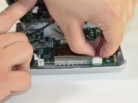
Use the flat end of the spudger to pry the lid off from the two connectors holding it to the body of the dock.
-
-
-
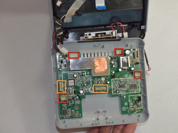
Carefully pull up and out the four electrical connectors and two ribbon connectors that connect the bottom panel to the dock.
-
Electrical Connectors
-
Ribbon Connectors
-
-
-
Unscrew the ten 6 mm Phillips #00 screws holding the board in place.
-


To reassemble your device, follow these instructions in reverse order.
To reassemble your device, follow these instructions in reverse order.
crwdns2915084:0crwdne2915084:0

Cal Poly, Team 3-48, Amido Spring 2013 crwdns2935289:0Cal Poly, Team 3-48, Amido Spring 2013crwdne2935289:0
CPSU-AMIDO-S13S3G48
crwdns2931471:04crwdne2931471:0
crwdns2935297:06crwdne2935297:0
crwdns2947410:01crwdne2947410:0
My philips dc 320 /37 A do not sown time digits and frecvency digits . Where can I find schematic diagram?
Thank you